1
GS Series AC Drive
Ethernet Interface
User Manual
WARNING Thank you for purchasing automation equipment from Automationdirect.com®, doing business as
AutomationDirect. We want your new automation equipment to operate safely. Anyone who installs
or uses this equipment should read this publication (and any other relevant publications) before
installing or operating the equipment.
To minimize the risk of potential safety problems, you should follow all applicable local and national
codes that regulate the installation and operation of your equipment. These codes vary from area to
area and usually change with time. It is your responsibility to determine which codes should be
followed, and to verify that the equipment, installation, and operation is in compliance with the
latest revision of these codes.
At a minimum, you should follow all applicable sections of the National Fire Code, National
Electrical Code, and the codes of the National Electrical Manufacturer's Association (NEMA). There
may be local regulatory or government offices that can also help determine which codes and
standards are necessary for safe installation and operation.
Equipment damage or serious injury to personnel can result from the failure to follow all applicable
codes and standards. We do not guarantee the products described in this publication are suitable for
your particular application, nor do we assume any responsibility for your product design,
installation, or operation.
Our products are not fault-tolerant and are not designed, manufactured or intended for use or resale
as on-line control equipment in hazardous environments requiring fail-safe performance, such as in
the operation of nuclear facilities, aircraft navigation or communication systems, air traffic control,
direct life support machines, or weapons systems, in which the failure of the product could lead
directly to death, personal injury, or severe physical or environmental damage ("High Risk
Activities"). AutomationDirect specifically disclaims any expressed or implied warranty of fitness for
High Risk Activities.
For additional warranty and safety information, see the Terms and Conditions section of our catalog.
If you have any questions concerning the installation or operation of this equipment, or if you need
additional information, please call us at 770-844-4200.
This publication is based on information that was available at the time it was printed. At
AutomationDirect we constantly strive to improve our products and services, so we reserve the right
to make changes to the products and/or publications at any time without notice and without any
obligation. This publication may also discuss features that may not be available in certain revisions of
the product.
Trademarks
This publication may contain references to products produced and/or offered by other companies.
The product and company names may be trademarked and are the sole property of their respective
owners. AutomationDirect disclaims any proprietary interest in the marks and names of others.
Copyright 2002, 2010, Automationdirect.com® Incorporated
All Rights Reserved
No part of this manual shall be copied, reproduced, or transmitted in any way without the prior,
written consent of Automationdirect.com® Incorporated. AutomationDirect retains the exclusive
rights to all information included in this document.
AVERTISSEMENT Nous vous remercions d'avoir acheté l'équipement d'automatisation de Automationdirect.com®, en
faisant des affaires comme AutomationDirect. Nous tenons à ce que votre nouvel équipement
d'automatisation fonctionne en toute sécurité. Toute personne qui installe ou utilise cet équipement
doit lire la présente publication (et toutes les autres publications pertinentes) avant de l'installer ou
de l'utiliser.
Afin de réduire au minimum le risque d'éventuels problèmes de sécurité, vous devez respecter tous
les codes locaux et nationaux applicables régissant l'installation et le fonctionnement de votre
équipement. Ces codes diffèrent d'une région à l'autre et, habituellement, évoluent au fil du temps. Il
vous incombe de déterminer les codes à respecter et de vous assurer que l'équipement, l'installation
et le fonctionnement sont conformes aux exigences de la version la plus récente de ces codes.
Vous devez, à tout le moins, respecter toutes les sections applicables du Code national de
prévention des incendies, du Code national de l'électricité et des codes de la National Electrical
Manufacturer's Association (NEMA). Des organismes de réglementation ou des services
gouvernementaux locaux peuvent également vous aider à déterminer les codes ainsi que les normes
à respecter pour assurer une installation et un fonctionnement sûrs.
L'omission de respecter la totalité des codes et des normes applicables peut entraîner des dommages
à l'équipement ou causer de graves blessures au personnel. Nous ne garantissons pas que les produits
décrits dans cette publication conviennent à votre application particulière et nous n'assumons aucune
responsabilité à l'égard de la conception, de l'installation ou du fonctionnement de votre produit.
Nos produits ne sont pas insensibles aux défaillances et ne sont ni conçus ni fabriqués pour
l'utilisation ou la revente en tant qu'équipement de commande en ligne dans des environnements
dangereux nécessitant une sécurité absolue, par exemple, l'exploitation d'installations nucléaires, les
systèmes de navigation aérienne ou de communication, le contrôle de la circulation aérienne, les
équipements de survie ou les systèmes d'armes, pour lesquels la défaillance du produit peut
provoquer la mort, des blessures corporelles ou de graves dommages matériels ou
environnementaux («activités à risque élevé»). La société AutomationDirect nie toute garantie
expresse ou implicite d'aptitude à l'emploi en ce qui a trait aux activités à risque élevé.
Pour des renseignements additionnels touchant la garantie et la sécurité, veuillez consulter la section
Modalités et conditions de notre documentation. Si vous avez des questions au sujet de l'installation
ou du fonctionnement de cet équipement, ou encore si vous avez besoin de renseignements
supplémentaires, n'hésitez pas à nous téléphoner au 770-844-4200.
Cette publication s'appuie sur l'information qui était disponible au moment de l'impression. À la
société AutomationDirect, nous nous efforçons constamment d'améliorer nos produits et services.
C'est pourquoi nous nous réservons le droit d'apporter des modifications aux produits ou aux
publications en tout temps, sans préavis ni quelque obligation que ce soit. La présente publication
peut aussi porter sur des caractéristiques susceptibles de ne pas être offertes dans certaines versions
révisées du produit.
Marques de commerce
La présente publication peut contenir des références à des produits fabriqués ou offerts par d'autres
entreprises. Les désignations des produits et des entreprises peuvent être des marques de commerce
et appartiennent exclusivement à leurs propriétaires respectifs. AutomationDirect nie tout intérêt
dans les autres marques et désignations.
Copyright 2002, 2010, Automationdirect.com® Incorporated
Tous droits réservés
Nulle partie de ce manuel ne doit être copiée, reproduite ou transmise de quelque façon que ce soit
sans le consentement préalable écrit de la société Automationdirect.com® Incorporated.
AutomationDirect conserve les droits exclusifs à l'égard de tous les renseignements contenus dans le
présent document.
GS SERIES AC DRIVE
ETHERNET INTERFACE
USER MANUAL
Please include the Manual Number and the Manual Issue, both shown below, when
communicating with Technical Support regarding this publication.
Manual Number:
GS-EDRV-M
Issue:
Third Edition
Issue Date:
05/2011
Publication History
Issue
Date
Description of Changes
First Edition
8/02/02
Original
1st Edition, Revision A
3/14/03
Added Input WORD functions
1st Edition, Revision B
8/12/05
Website publication only; Corrected Output Word Map & Warnings
Second Edition
02/2010
Revised “Reading/Writing From/To the Drive” & “Input/Output Word
Map” sections
Third Edition
05/2011
Added GS-EDRV100 product information and specifications.
TABLE OF CONTENTS
Manual Overview . . . . . . . . . . . . . . . . . . . . . . . . . . . . . . .3
Overview of this Publication . . . . . . . . . . . . . . . . . . . . . . . . . . . . . . . . . . . . .3
Who Should Read This Manual . . . . . . . . . . . . . . . . . . . . . . . . . . . . . . . . . .3
Supplemental Publications . . . . . . . . . . . . . . . . . . . . . . . . . . . . . . . . . . . . . .3
Technical Support . . . . . . . . . . . . . . . . . . . . . . . . . . . . . . . . . . . . . . . . . . . .3
Special Symbols . . . . . . . . . . . . . . . . . . . . . . . . . . . . . . . . . . . . . . . . . . . . . .3
GS-EDRV Overview . . . . . . . . . . . . . . . . . . . . . . . . . . . . . .4
Package Contents . . . . . . . . . . . . . . . . . . . . . . . . . . . . . . . . . . . . . . . . . . . .5
GS-EDRV Board Layout . . . . . . . . . . . . . . . . . . . . . . . . . . .6
Power Terminals . . . . . . . . . . . . . . . . . . . . . . . . . . . . . . . . . . . . . . . . . . . . . .6
Communication Ports . . . . . . . . . . . . . . . . . . . . . . . . . . . . . . . . . . . . . . . . .7
DIP Switches . . . . . . . . . . . . . . . . . . . . . . . . . . . . . . . . . . . . . . . . . . . . . . . .7
LED Indicators . . . . . . . . . . . . . . . . . . . . . . . . . . . . . . . . . . . . . . . . . . . . . . .7
Setting the GS-EDRV Address . . . . . . . . . . . . . . . . . . . . . .8
Setting Module ID with DIP Switches . . . . . . . . . . . . . . . . . . . . . . . . . . . . . .8
Setting TCP/IP Address with NetEdit . . . . . . . . . . . . . . . . . . . . . . . . . . . . . .9
Network Connections . . . . . . . . . . . . . . . . . . . . . . . . . . .10
10Base-T Connections . . . . . . . . . . . . . . . . . . . . . . . . . . . . . . . . . . . . . . . .10
GS-EDRV100 Overview . . . . . . . . . . . . . . . . . . . . . . . . . .11
Package Contents . . . . . . . . . . . . . . . . . . . . . . . . . . . . . . . . . . . . . . . . . . .12
GS-EDRV100 Layout . . . . . . . . . . . . . . . . . . . . . . . . . . . .13
Power Terminals . . . . . . . . . . . . . . . . . . . . . . . . . . . . . . . . . . . . . . . . . . . . .13
Communication Ports . . . . . . . . . . . . . . . . . . . . . . . . . . . . . . . . . . . . . . . .13
DIP Switches . . . . . . . . . . . . . . . . . . . . . . . . . . . . . . . . . . . . . . . . . . . . . . .14
LED Indicators . . . . . . . . . . . . . . . . . . . . . . . . . . . . . . . . . . . . . . . . . . . . . .14
Table of Contents
Setting the GS-EDRV100 Address . . . . . . . . . . . . . . . . . .15
Setting Module ID with DIP Switches . . . . . . . . . . . . . . . . . . . . . . . . . . . . .15
Setting TCP/IP Address with NetEdit . . . . . . . . . . . . . . . . . . . . . . . . . . . . .16
Network Connections . . . . . . . . . . . . . . . . . . . . . . . . . . .17
10/100Mbps Connections . . . . . . . . . . . . . . . . . . . . . . . . . . . . . . . . . . . . .17
GS-EDRV(100) to GS Series AC Drive Connection . . . . . .18
Setting the GS Series AC Drive Parameters . . . . . . . . . . . . . . . . . . . . . . . . .18
GS-EDRV(100) to ERM Module Connection . . . . . . . . . . .19
Reserved PLC Memory for the GS-EDRV(100) . . . . . . . . . . . . . . . . . . . . . .19
Reading/Writing From/To the Drive . . . . . . . . . . . . . . . . .20
Input/Output Word Map . . . . . . . . . . . . . . . . . . . . . . . . . . . . . . . . . . . . . .20
Examples – I/O Word Mapping . . . . . . . . . . . . . . . . . . . . . . . . . . . . . . . . .23
Built-in Web Server . . . . . . . . . . . . . . . . . . . . . . . . . . . . .25
Troubleshooting – H24-ERM-M . . . . . . . . . . . . . . . . . . . .25
Refer to Ethernet Remote Master User Manual H24-ERM-M . . . . . . . . . . . .25
Application Example: Modbus TCP/IP . . . . . . . . . . . . . . .26
ii
GS Series AC Drive Ethernet Interface User Manual
3rd Edition
05/2011
GS-EDRV(100) Ethernet Interface
Manual Overview
Overview of this Publication
The GS AC Drive Ethernet Interface User Manual describes the installation,
configuration, and operation of GS AC Drive Ethernet Interface cards.
Who Should Read This Manual
This manual contains important information for those who will install, maintain,
and/or operate any GS Series AC Drive Ethernet Interface card.
Supplemental Publications
The Ethernet Remote Master Module Manual (H24-ERM-M) is available from
AutomationDirect and may be useful for your application.
Technical Support
By Telephone: 770-844-4200
(Mon.-Fri., 9:00 a.m.-6:00 p.m. E.T.)
On the Web: www.automationdirect.com
Our technical support group is glad to work with you in answering your questions.
If you cannot find the solution to your particular application, or, if for any reason
you need additional technical assistance, please call technical support at
770-844-4200. We are available weekdays from 9:00 a.m. to 6:00 p.m. Eastern
Time.
We also encourage you to visit our web site where you can find technical and
non-technical information about our products and our company. Visit us at
www.automationdirect.com.
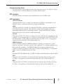
Special Symbols
When you see the “notepad” icon in the left-hand margin, the paragraph to its
immediate right will be a special note.
When you see the “exclamation mark” icon in the left-hand margin, the paragraph to
its immediate right will be a WARNING. This information could prevent injury, loss
of property, or even death (in extreme cases).
3rd Edition
05/2011
GS Series AC Drive Ethernet Interface User Manual
3
GS-EDRV(100) Ethernet Interface
GS-EDRV Overview
The GS-EDRV provides a low-cost, high-performance 10BaseT Ethernet link
between a control system and a GS Series AC Drive. The control system can be
any of the following:
• DL205 CPU, DL405 CPU, or a WinPLC, with the appropriate Ethernet Remote
Master module (H2-ERM or H4-ERM).
• A Productivity3000 CPU using the onboard Ethernet port.
• A PC running Entivity’s ThinknDo software, a PC using a custom device driver that
was developed using our Ethernet SDK, or a PC running KEPDirect EBC or OPC
Server.
• Any independent I/O controller with a Modbus TCP/IP driver.
The GS-EDRV mounts on DIN rail and utilizes cable connections and, if needed,
Ethernet switches or hubs to communicate to the AC drive.
The functions of the interface are as follows:
• process input signals from the AC drive.
• format these signals to conform to the Ethernet standard.
• transmit converted signals to the control system.
• receive and translate output signals from the control system.
• sends the output signals to the drive.
The control function is NOT performed by the interface. The control function is
performed by one of the control systems mentioned above. The I/O mapping
function is performed by an H2(4)-ERM module (purchased separately). The
H2(4)-ERM module is configured with the ERM Workbench Utility which is part of
the DirectSOFT PLC programming software.
4
GS Series AC Drive Ethernet Interface User Manual
3rd Edition
05/2011
GS-EDRV(100) Ethernet Interface
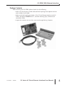
Package Contents
After receiving the GS-EDRV, please check for the following:
• Make sure that the part number indicated on the package corresponds with the
part number of your order.
• Make sure that the package includes a GS AC Drive Ethernet Interface card (GSEDRV), one piece of SNAPTRACK™, two DIN mounting clips, and one serial
connection cable.
• Inspect the contents to insure they were not damaged during shipment.
3rd Edition
05/2011
GS Series AC Drive Ethernet Interface User Manual
5
GS-EDRV(100) Ethernet Interface
GS-EDRV Board Layout
DIP Switches
Communication Ports
Power Terminals
LED Indicators
Chassis or system Ground connection
Negative connection (–) or 0VDC
Positive connection (+) or +24VDC
Power Terminals
Power for the GS-EDRV is connected directly to the card using a nominal 24VDC
supply (+24VDC, –0VDC). The GNDC terminal is for a chassis or system Ground.
Input Voltage
18–33 VDC with a 24VDC nominal supply
Input Current
90–135 mA
6
GS Series AC Drive Ethernet Interface User Manual
3rd Edition
05/2011
GS-EDRV(100) Ethernet Interface
Communication Ports
Two comm ports are provided to make the connection from a GS Series AC drive
(Serial port) to an Ethernet device or network (Ethernet port).
DIP Switches
The DIP Switches are used to set the Module ID for the GS-EDRV card.
LED Indicators
STATUS Indicator
The green STATUS LED is steady ON when the GS-EDRV is connected to a GS
Series AC drive and communication has been established.
LINK
The green LINK LED is steady ON when the GS-EDRV is correctly connected to an
active device on the network. The LINK LED verifies that the proper cables are
connected, and the card is functioning correctly. If a mismatch with the 10BaseT
connections occurs this LED will not be illuminated.
ACTIVE
The green ACTIVE LED flashes to indicate that the card sees data travelling on the
network. If any network device is sending or receiving data, the ACTIVE LED will
be illuminated. In idle mode (no network traffic) this LED is OFF. During heavy
communication loads this LED will be steady ON.
ERROR Indicator
If the GS-EDRV’s red Error (ERROR) indicator is flashing or steady ON, a fatal
error has occurred. The error may be in the card itself, or a network problem may
be causing this symptom. The ERROR indication can be caused by a faulty
ground, an electrical spike or other types of electrical disturbances. Cycle power
to the system to attempt clearing the error.
RTS
The green RTS LED indicates the GS-EDRV is ready to send information to the AC drive.
TXD
The green TXD LED flashes to indicate that the card sees data traveling to the
AC drive. During heavy communication loads, this LED will be steady ON.
RXD
The green RXD LED flashes to indicate that the card sees data traveling from the
AC drive. During heavy communication loads this LED will be steady ON.
3rd Edition
05/2011
GS Series AC Drive Ethernet Interface User Manual
7
GS-EDRV(100) Ethernet Interface
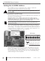
Setting the GS-EDRV Address
Each GS-EDRV must have an identification (ID) or address in order to be
recognized on the network, and each ID must be unique.
WARNING: Duplicate IDs on the same network will cause unpredictable results and
must be avoided.
Setting Module ID with DIP Switches
You can use the DIP switch to set the ID to a number from one to sixty-three. Do
not use ID “0” for communication.
If the DIP switch is set to a number greater than 0, the software tools are
disabled from setting the ID. Again, the software tools will only allow changes
to the ID if the DIP switch setting is 0 (zero, all switches OFF).
The DIP switch settings are read only at power-up. You must cycle power if you
change the DIP switches.
The GS-EDRV contains eight individual DIP switches, but only six of these are
active. You will find that the switches on the printed circuit board are labeled 0
(zero) through 7. The numbers on the printed circuit board indicate the power of
2 represented by each individual switch. For example, switch 0 represents 20 (or
1), switch 1 is 21 (or 2), switch 2 is 22 (or 4), and so on.
DIP Switches
OFF
7 6 5 4 3 2 1 0
25 2 4 2 3 2 2 2 1 2 0
Not
(32) (16) (8) (4) (2) (1)
used
Binary value
The ID equals the sum of the binary values of the slide switches set in the ON
position. For example, if you set slide switches 1, 2, and 3 to the ON position,
the ID will be 14. This is found by adding 8+4+2=14. The maximum value you
can set on the DIP switch is 32+16+8+4+2+1=63. This is achieved by setting
switches 0 through 5 to the ON position.
8
GS Series AC Drive Ethernet Interface User Manual
3rd Edition
05/2011
GS-EDRV(100) Ethernet Interface
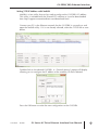
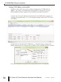
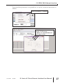
Setting TCP/IP Address with NetEdit
NetEdit is a free utility that can be used to configure the GS-EDRV’s IP address.
This utility is included with the DirectSOFT software or it can be downloaded
from http://support.automationdirect.com/downloads.html.
Connect your PC to the Ethernet network that the GS-EDRV is currently on and
open the NetEdit utility. If it is not already selected, select the TCP/IP tab as seen
below.
Double click on the desired GS-EDRV. A “General Settings” popup will display
allowing you to configure the IP address of the module you have selected.
Press the OK button to write the new configuration to the GS-EDRV.
3rd Edition
05/2011
GS Series AC Drive Ethernet Interface User Manual
9
GS-EDRV(100) Ethernet Interface
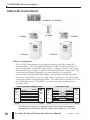
Network Connections
DL205 PLC w/ H2-ERM
SE-SW5U
GS-EDRV
GS3 Drive
GS-EDRV
GS3 Drive
10Base-T Connections
The GS-EDRV Ethernet port has an eight-pin modular jack that accepts RJ45
connector plugs. UTP (Unshielded Twisted-Pair) cable is rated according to its
data-carrying ability (bandwidth) and is given a “category” number. We strongly
recommend using a category 5 cable for all Ethernet 10Base-T connections. For
convenient and reliable networking, we recommend that you purchase
commercially manufactured cables (cables with connectors already attached).
To connect an GS-EDRV (or PC) to a hub, switch, or repeater, use a patch cable
(sometimes called a straight-through cable). The cable used to connect a PC or an
H2(4)-ERM directly to an GS-EDRV or to connect two hubs is referred to as a
crossover cable.
Patch (Straight-through) Cable
EDRV
OR/WHT
TD+ 1
OR
TD- 2
GRN/WHT
RD+ 3
4 BLU
BLU/WHT
5
RD- 6 GRN
BRN/WHT
7
BRN
8
RJ45
OR/WHT
OR
GRN/WHT
BLU
BLU/WHT
GRN
BRN/WHT
BRN
HUB
1
2
3
4
5
6
7
8
RD+
RDTD+
TD-
RJ45
Crossover Cable
EDRV
OR/WHT
TD+ 1
OR
TD- 2
GRN/WHT
RD+ 3
4 BLU
5 BLU/WHT
RD- 6 GRN
7 BRN/WHT
8 BRN
GRN/WHT
GRN
OR/WHT
BLU
BLU/WHT
OR
BRN/WHT
BRN
RJ45
PC
1
2
3
4
5
6
7
8
TD+
TDRD+
RD-
RJ45
This diagram illustrates the standard wire positions in the RJ45 connector.
We recommend all Ethernet 10BaseT cables to be Category 5, UTP cable.
10
GS Series AC Drive Ethernet Interface User Manual
3rd Edition
05/2011
GS-EDRV(100) Ethernet Interface
GS-EDRV100 Overview
The GS-EDRV100 provides a low cost, high-performance 10/100Mbps Ethernet
link between a control system and a GS Series AC Drive. The control system can
be any of the following:
• DL205 CPU, DL405 CPU, or a WinPLC, with the appropriate Ethernet Remote
Master module (H2-ERM or H4-ERM).
• A Productivity3000 CPU using the onboard Ethernet port.
• A PC running Entivity’s ThinknDo software, a PC using a custom device driver that
was developed using our Ethernet SDK, or a PC running KEPDirect EBC or OPC
Server.
• Any independent I/O controller with a Modbus TCP/IP driver.
The GS-EDRV100 has an encapsulated compact DIN rail mounted design
allowing for minimal space requirements. With the appropriate cable connections
and, if needed, Ethernet switches or hubs, the GS-EDRV100 will allow you to
communicate with your AC drive over qualified Ethernet networks.
The functions of the interface are as follows:
• process input signals from the AC drive.
• format these signals to conform to the Ethernet standard.
• transmit converted signals to the control system.
• receive and translate output signals from the control system.
• sends the output signals to the drive.
The control function is NOT performed by the interface. The control function is
performed by one of the control systems mentioned above. The I/O mapping
function is performed by an H2(4)-ERM module (purchased separately). The
H2(4)-ERM module is configured with the ERM Workbench Utility which is part of
the DirectSOFT PLC programming software.
3rd Edition
05/2011
GS Series AC Drive Ethernet Interface User Manual
11
GS-EDRV(100) Ethernet Interface
Package Contents
After receiving the GS-EDRV100, please check for the following:
• Make sure that the part number indicated on the package corresponds with the
part number of your order.
• Make sure that the package includes a GS AC Drive Ethernet Interface card (GSEDRV100), one DIN rail mounting clip, one 3-wire terminal block, and one serial
connection cable (2ft in length).
• Inspect the contents to insure they were not damaged during shipment.
12
GS Series AC Drive Ethernet Interface User Manual
3rd Edition
05/2011
GS-EDRV(100) Ethernet Interface
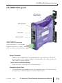
GS-EDRV100 Layout
DIP Switches
(under cover)
LED Indicators
Serial Port
Ethernet Port
Power Terminals
(Class 2 power recommended)
Positive connection (+) or +10-36VDC
Negative connection (–) or 0VDC
Chassis or system Ground connection
Power Terminals
Power for the GS-EDRV100 is connected directly to the card using a 10-36VDC
power supply (a Class 2 power supply is recommended). The Chassis terminal is
for a chassis or system Ground.
Input Current and Voltage Ratings
220mA@10VDC, 70mA@24VDC, or 50mA@36VDC.
Communication Ports
Two comm ports are provided to make the connection from a GS Series AC drive
(Serial port) to an Ethernet device or network (Ethernet port).
3rd Edition
05/2011
GS Series AC Drive Ethernet Interface User Manual
13
GS-EDRV(100) Ethernet Interface
DIP Switches
The DIP Switches are used to set the Module ID for the GS-EDRV100 card.
LED Indicators
STA
The STA or STATUS LED is steady ON when the GS-EDRV100 is connected to a
GS Series AC drive and communication has been established.
SPD
The SPD or SPEED LED is used to represent the Ethernet speed. The LED will be
ON when the Ethernet speed is 100Mbps and OFF when the speed is 10Mbps.
TXD
The TXD or TRANSMIT DATA LED flashes to indicate that the GS-EDRV100 is
sending data through the serial port to the AC drive.
ERR
If the GS-EDRV100’s ERR (ERROR) indicator is ON, a critical error has occurred.
The error may be in the card itself, or a network problem may be causing this
symptom. The ERROR indication can be caused by a faulty ground, an electrical
spike or other types of electrical disturbances. Cycle power to the system to
attempt clearing the error. The ERROR LED will also flash (once per second)
when a firmware update is in progress.
LK/A
The LK/A or LINK GOOD/ACTIVITY LED flashes to indicate that the card sees data
traveling on the Ethernet network. If any network device is sending or receiving
data, the LK/A LED will be flashing. During heavy communication loads, this
indicator will be steady ON. If the LED is OFF, then a problem with the Ethernet
connection has been detected.
RXD
The RXD or RECEIVE DATA LED flashes to indicate that the GS-EDRV100 is
receiving data through the serial port from the AC drive.
14
GS Series AC Drive Ethernet Interface User Manual
3rd Edition
05/2011
GS-EDRV(100) Ethernet Interface
Setting the GS-EDRV100 Address
Each GS-EDRV100 must have an identification (ID) or address in order to be
recognized on the network, and each ID must be unique.
WARNING: Duplicate IDs on the same network will cause unpredictable results and
must be avoided.
Setting Module ID with DIP Switches
You can use the DIP switch to set the ID to a number from one to sixty-three. Do
not use ID “0” for communication.
If the DIP switch is set to a number greater than 0, the software tools are
disabled from setting the ID. Again, the software tools will only allow changes
to the ID if the DIP switch setting is 0 (zero, all switches OFF).
The DIP switch settings are read only at power-up. You must cycle power if you
change the DIP switches.
The GS-EDRV100 contains eight individual DIP switches, but only six of these are
active. You will find that the switches on the printed circuit board are labeled 0
(zero) through 7. The numbers on the printed circuit board indicate the power of
2 represented by each individual switch. For example, switch 0 represents 20 (or
1), switch 1 is 21 (or 2), switch 2 is 22 (or 4), and so on.
DIP Switches
OFF
7 6 5 4 3 2 1 0
25 2 4 2 3 2 2 2 1 2 0
Not
(32) (16) (8) (4) (2) (1)
used
Binary value
The ID equals the sum of the binary values of the slide switches set in the ON
position. For example, if you set slide switches 1, 2, and 3 to the ON position,
the ID will be 14. This is found by adding 8+4+2=14. The maximum value you
can set on the DIP switch is 32+16+8+4+2+1=63. This is achieved by setting
switches 0 through 5 to the ON position.
3rd Edition
05/2011
GS Series AC Drive Ethernet Interface User Manual
15
GS-EDRV(100) Ethernet Interface
Setting TCP/IP Address with NetEdit
NetEdit is a free utility that can be used to configure the GS-EDRV100’s IP
address. This utility is included with the DirectSOFT software or it can be
downloaded from http://support.automationdirect.com/downloads.html.
Connect your PC to the Ethernet network that the GS-EDRV100 is currently on
and open the NetEdit utility. If it is not already selected, select the TCP/IP tab as
seen below.
Double click on the desired GS-EDRV100. A “General Settings” popup will
display allowing you to configure the IP address of the module you have selected.
Press the OK button to write the new configuration to the GS-EDRV100.
16
GS Series AC Drive Ethernet Interface User Manual
3rd Edition
05/2011
GS-EDRV(100) Ethernet Interface
Network Connections
DL205 PLC w/ H2-ERM
GS-EDRV100
GS-EDRV100
SE-SW5U
GS3 Drive
GS3 Drive
10/100Mbps Connections
The GS-EDRV100 Ethernet port has an eight-pin modular jack that accepts RJ45
connector plugs. UTP (Unshielded Twisted-Pair) cable is rated according to its
data-carrying ability (bandwidth) and is given a “category” number. We strongly
recommend using a category 5 cable for all Ethernet 10/100Mbps connections.
For convenient and reliable networking, we recommend that you purchase
commercially manufactured cables (cables with connectors already attached).
To connect an GS-EDRV100 (or PC) to a hub, switch, or repeater, use a patch
cable (sometimes called a straight-through cable). The cable used to connect a
PC or an H2(4)-ERM directly to an GS-EDRV100 or to connect two hubs is
referred to as a crossover cable.
Patch (Straight-through) Cable
EDRV
OR/WHT
TD+ 1
OR
TD- 2
GRN/WHT
RD+ 3
4 BLU
BLU/WHT
5
RD- 6 GRN
BRN/WHT
7
BRN
8
RJ45
OR/WHT
OR
GRN/WHT
BLU
BLU/WHT
GRN
BRN/WHT
BRN
HUB
1
2
3
4
5
6
7
8
RD+
RDTD+
TD-
RJ45
Crossover Cable
EDRV
OR/WHT
TD+ 1
OR
TD- 2
GRN/WHT
RD+ 3
4 BLU
5 BLU/WHT
RD- 6 GRN
7 BRN/WHT
8 BRN
GRN/WHT
GRN
OR/WHT
BLU
BLU/WHT
OR
BRN/WHT
BRN
RJ45
PC
1
2
3
4
5
6
7
8
TD+
TDRD+
RD-
RJ45
This diagram illustrates the standard wire positions in the RJ45 connector.
We recommend all Ethernet 10/100Mbps cables to be Category 5, UTP cable.
3rd Edition
05/2011
GS Series AC Drive Ethernet Interface User Manual
17
GS-EDRV(100) Ethernet Interface
GS-EDRV(100) to GS Series AC Drive Connection
A serial connection cable (2ft. in length) is provided with the GS-EDRV(100) to make
an RS-485 connection with a GS Series AC Drive.
When using the GS2 Series AC Drive , DIP Switch 2 and 3 (SW2 and SW3) on the
drive must be set to RS485.
RS485
SW3
SW2
Switches SW2 and SW3 on the drive
must be set to RS485 for an RS-485
connection (GS2 Series Only).
RS232
Setting the GS Series AC Drive Parameters
The following parameters need to be set in the GS Series AC Drive in order to
operate properly with the GS-EDRV(100) interface card.
P3.00: 03 or 04 – Operation Determined by RS232C/RS485 interface. Keypad
STOP is enabled (03) or disabled (04).
P4.00: 05 – Frequency determined by RS232/RS485 communication interface
P9.00: xx – Communication address 01-254 (unique for each device)
P9.01: 01 – 9600 baud data transmission speed
P9.02: 05 – MODBUS RTU mode <8 data bits, odd parity, 1 stop bit>
The previous list of parameter settings is the minimum required to communicate with a
GS Series AC Drive through a GS-EDRV(100) interface card. There may be other
parameters that need to be set to meet the needs of your application.
18
GS Series AC Drive Ethernet Interface User Manual
3rd Edition
05/2011
GS-EDRV(100) Ethernet Interface
GS-EDRV(100) to ERM Module Connection
The GS-EDRV(100) interface card can be added to any H2(4)-ERM module using
the ERM Workbench Utility. For more details on selecting and configuring slaves
for the ERM module, see CHAPTER 4 of the H24-ERM-M.
Reserved PLC Memory for the GS-EDRV(100)
Once the GS-EDRV(100) is added the ERM module, 16 WORD inputs and 11
WORD outputs are mapped back to the PLC. The assigned PLC addresses are
shown in the ERM Workbench Utility.
16 Input WORDS
11 Output WORDS
3rd Edition
05/2011
GS Series AC Drive Ethernet Interface User Manual
19
GS-EDRV(100) Ethernet Interface
Reading/Writing From/To the Drive
The control function is NOT performed by the interface. The control function is
performed by the control system. The I/O mapping function is performed by an
H2(4)-ERM module (purchased separately). The H2(4)-ERM module is configured
with the ERM Workbench Utility which is part of the DirectSOFT PLC programming
software.
Input/Output Word Map
The Input and Output WORDS for the GS-EDRV(100) are mapped to specific
parameters and functions in the GS Series AC Drives. The Word Map tables on
the following pages show the Input and Output WORDS and their functions.
Using the Input/Output Words
Output Words 10 and 11 are used in conjunction with Input Words 15 and 16 to
Read/Write AC drive parameters that are not mapped to other Input and Output
Words. By using Output Words 10 and 11 with Input Words 14 and 15, you have
the ability to read/write most AC drive parameters.
P9.29 is the only Communication Parameter (P9.xx range) that can be written to using
the Read/Write Input/Output Words (IW 15 & 16; OW 10 & 11). However, these
Input/Output Words can be used to read values from all of the drive Communication
Parameters (P9.xx range).
20
GS Series AC Drive Ethernet Interface User Manual
3rd Edition
05/2011
GS-EDRV(100) Ethernet Interface
Input Word Map
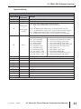
Input WORD Map
Input Word
Parameter
Function
Reference
1
2
N/A
Present Output Frequency
N/A
Present Output Current
Bit 0 = Drive Serial Comm External Fault bit (P9.29)
Bit 1 = EDRV internal EDRV-to-Drive Comm Fault bit
3
Drive P9.29
&
00 = 0:
EDRV Comm 01 = 1:
Fault Bit
10 = 2:
11 = 3:
no EDRV-to-drive comm fault; no manual comm ext fault
no EDRV-to-drive comm fault; manual comm ext fault triggered
EDRV-to-drive comm fault; no manual comm ext fault
EDRV-to-drive comm fault; manual comm ext fault triggered
P6.31 = Status Monitor 1 – Error Codes from AC Drive.
00:
01:
02:
03:
04:
05:
06:
07:
08:
09:
10:
No fault occurred
Over-current(oc)
Over-voltage(ov)
Overheat (oH)
Overload (oL)
Overload 1 (oL1)
Overload 2 (oL2)
External Fault (EF)
CPU failure 1 (CF1)
CPU failure 2 (CF2)
CPU failure 3 (CF3)
11:
12:
13:
14:
15:
16:
17:
18:
19:
20:
Hardware Protection Failure (HPF)
Over-current during accel (OCA)
Over-current during decel (Ocd)
Over-current during steady state (Ocd)
Ground fault or fuse failure (GFF)
Low voltage (Lv)
Input power 3-phase loss
External Base-Block (bb)
Auto adjust accel/decel failure (cFA)
Software protection code (codE)
4
P6.31
5
6
7
8
9
10
11
12
13
14
P9.16
Block Transfer Parameter 6 – User defined read value
P9.17
Block Transfer Parameter 7 – User defined read value
P9.18
Block Transfer Parameter 8 – User defined read value
P9.19
Block Transfer Parameter 9 – User defined read value
P9.20
Block Transfer Parameter 10 – User defined read value
P9.21
Block Transfer Parameter 11 – User defined read value
P9.22
Block Transfer Parameter 12 – User defined read value
P9.23
Block Transfer Parameter 13 – User defined read value
P9.24
Block Transfer Parameter 14 – User defined read value
P9.25
Block Transfer Parameter 15 – User defined read value
Table continued next page.
3rd Edition
05/2011
GS Series AC Drive Ethernet Interface User Manual
21
GS-EDRV(100) Ethernet Interface
Input Word Map (continued)
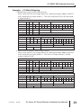
Input WORD Map (continued)
Input Word
Parameter
Function
Reference
Read/Write
Response
15
Response to a read/write request (Output Word 10)
Bit: 00-07 = Memory Reference
08-11 = Memory type number (i.e. 0 to A for P0 to P10)
12-13 = Operation (works in conjunction with bit 15):
0=NOP, 9=Read accomplished, A=Write accomplished
Bit 12 set indicates a read operation.
Bit 13 set indicates a write operation.
Bit 15 set indicates the read or write op was accomplished.
Check bit 14 and Input Word 16 to see if an error occurred.
14 = Error status:
If set, an error has occurred. Error Code is stored in Word 16.
15 = Read/Write Status:
If set, the read or write operation was successful.
If Input Word 15 is a Read response, the value is stored here.
If Input Word 15 is an Error response, the error code is stored here.
Error Codes:
0x8010
HEIE_INVALID_REQUEST
0x8090
HEIE_NOT_INITIALIZED
0x8096
HEIE_INVALID_OPERATION
Read Request
0x006F
HEIE_INVALID_TYPE
Value
0x0091
HEIE_INVALID_MODE
0x008C
HEIE_INVALID_ADDRESS
0x0085
HEIE_RANGE_ERROR
0x006D
HEIE_SIZE_ERROR
16
Output Word Map
Output WORD Map
Output Word
1
2
3
4
5
6
7
8
9
10
11
22
Parameter
Function
Reference
P9.27
RUN Command
P9.26
RS-485 Speed Reference
P9.28
Direction Command (0 = Forward; 1 = Reverse)
P9.30
Serial Comm Fault Reset (0 = no action; 1 = Reset Fault)
P9.11
Block Transfer Parameter 1 – user defined write value
P9.12
Block Transfer Parameter 2 – user defined write value
P9.13
Block Transfer Parameter 3 – user defined write value
P9.14
Block Transfer Parameter 4 – user defined write value
P9.15
Block Transfer Parameter 5 – user defined write value
Read/Write
Request
Bit: 00-07 = Memory Reference
08-11 = Memory type number (i.e. 0 to A for P0 to P10)
12-13 = Operation: 00=NOP, 01=Read, 10=Write, 11=Undefined
14
= Undefined for request
Write Request
If Output Word 10 is a Write request, the value to be written is placed here.
Value
GS Series AC Drive Ethernet Interface User Manual
3rd Edition
05/2011
GS-EDRV(100) Ethernet Interface
Examples – I/O Word Mapping
1) Read P9.29 (Serial Comm External Fault):
Write value 0x191D into Output Word 10, and the parameter address 0x991D
will come back into Input Word 15. The value read from P9.29 will be stored
in Input Word 16.
OW 10: Read Request: Read from drive parameter 9.29
n/a operation parameter group #
parameter memory reference #
Bit #
15 14 13 12 11 10 9 8
7 6 5 4 3 2 1 0
Binary #
0 n/a 0
1
1 0 0 1
0 0 0 1 1 1 0 1
Hex #
0 n/a
1
9
1
D
Decimal #
0 n/a
1
9
29
Meaning
n/a n/a
read
parameter 9.29
IW 15: Read Response: Read from drive parameter 9.29
status error operation parameter group # parameter memory reference #
Bit #
15
14
13 12 11 10 9
8
7 6 5 4 3 2 1 0
Binary #
1
0
0
1
1
0
0
1
0 0 0 1 1 1 0 1
Hex #
9
9
1
D
Decimal #
9
9
29
Meaning
successful
read
parameter 9.29
2) Write to P9.29 (Serial Comm External Fault):
Write value 0x291D into Output Word 10, and the parameter address 0xA91D
will come back into Input Word 15. The value in Output Word 11 will be
written to drive P9.29.
OW 10: Write Request: Write to drive parameter 9.29
n/a operation parameter group #
parameter memory reference #
Bit #
15 14 13 12 11 10 9 8
7 6 5 4 3 2 1 0
Binary #
0 n/a 1
0
1 0 0 1
0 0 0 1 1 1 0 1
Hex #
0 n/a
2
9
1
D
Decimal #
0 n/a
2
9
29
Meaning
n/a n/a
write
parameter 9.29
IW 15: Write Response: Write to drive parameter 9.29
status error operation parameter group # parameter memory reference #
Bit #
15
14
13 12 11 10 9
8
7 6 5 4 3 2 1 0
Binary #
1
0
1
0
1
0
0
1
0 0 0 1 1 1 0 1
Hex #
A
9
1
D
Decimal #
10
9
29
Meaning
successful
write
parameter 9.29
3rd Edition
05/2011
GS Series AC Drive Ethernet Interface User Manual
23
GS-EDRV(100) Ethernet Interface
Examples – I/O Word Mapping (continued)
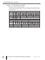
3) Read P0.00 (Motor Nameplate Voltage):
Write value 0x1000 into Output Word 10, and the parameter address 0x9000
will come back into Input Word 15. The value read from P0.00 will be stored
in Input Word 16.
OW 10: Read Request: Read from drive parameter 0.00
n/a operation parameter group #
parameter memory reference #
Bit #
15 14 13 12 11 10 9 8
7 6 5 4 3 2 1 0
Binary #
0 n/a 0
1
0 0 0 0
0 0 0 0 0 0 0 0
Hex #
0 n/a
1
0
0
0
Decimal #
0 n/a
1
0
0
Meaning
n/a n/a
read
parameter 0.00
IW 15: Read Response: Read from drive parameter 0.00
status error operation parameter group # parameter memory reference #
Bit #
15
14
13 12 11 10 9
8
7 6 5 4 3 2 1 0
Binary #
1
0
0
1
0
0
0
0
0 0 0 0 0 0 0 0
Hex #
9
0
0
0
Decimal #
9
0
0
Meaning
successful
read
parameter 0.00
24
GS Series AC Drive Ethernet Interface User Manual
3rd Edition
05/2011
GS-EDRV(100) Ethernet Interface
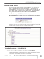
Built-in Web Server
The GS-EDRV(100) interface card has a built-in Web Server that allows you to
access AC drive data with your favorite Web browser. In order to access the
internal Web Server, you must first assign an IP address to the GS-EDRV(100) card.
The IP address can be assigned by using the NetEdit utility. You can then access
the GS-EDRV(100) card by typing the IP address into your Web browser.
Example
If the IP address of your GS-EDRV100 is 192.168.36.2, just enter
http://192.168.36.2 into the address field of your browser and press the Enter key.
The browser will then access the built-in Web Server as seen below. The available
parameter groups are shown with links to the parameter options.
Troubleshooting – H24-ERM-M
Refer to Ethernet Remote Master User Manual H24-ERM-M
Troubleshooting help for the ERM module and its slaves is available in CHAPTER 6
of the Ethernet Remote Master User Manual (H24-ERM-M).
3rd Edition
05/2011
GS Series AC Drive Ethernet Interface User Manual
25
GS-EDRV(100) Ethernet Interface
Application Example: Modbus TCP/IP
This application example shows how to use a GS-EDRV(100) to access a GS1,
GS2 or a DURApulse drive’s parameters for monitoring and control via the
Modbus TCP/IP protocol.
Equipment and software used in example:
• Two DURApulse Drives
• Two GS-EDRV100 Ethernet interface modules
• A Stride Ethernet switch (SE-SW5U-ST)
• A standard network PC with a Modbus TCP/IP driver installed
• ModScan software (available for download from Win-Tech at http://www.wintech.com/html/demos.htm). or any other Modbus TCP/IP interfacing software
Standard PC with Modscan
Stride Ethernet Switch
SE-SW5U-ST
GS-EDRV100
DURApulse AC Drive
26
GS-EDRV100
DURApulse AC Drive
GS Series AC Drive Ethernet Interface User Manual
3rd Edition
05/2011
GS-EDRV(100) Ethernet Interface
To monitor drive parameters using ModScan, set up the connection parameters as
follows:
Select Connection > Connect
Set-up:
Remote TCP/IP server
IP address of GS-EDRV100 card
Service port # 502
3rd Edition
05/2011
GS Series AC Drive Ethernet Interface User Manual
27
GS-EDRV(100) Ethernet Interface
Once a connection to the interface has been established, select the drive
parameters that you wish to monitor. See the table below for drive parameters
and their modbus addresses.
Choose the desired drive
parameters to monitor:
42331 – Speed Reference
42332 – Run Command
If you wish to write a value to the drive from this page, double click the address
you wish to change and a Write Register window will appear. Enter the new value
and select Update.
Modbus Addresses
Read/Write
Speed reference
Run command
Direction
External fault
Fault reset
Jog
Status
Frequency command
Output frequency
Output current
DC bus voltage
Output voltage
Motor RPM
Scale frequency (low)
Scale frequency (high)
Percent load
Firmware version
28
Hex
Modbus
091AH
42331
091BH
42332
091CH
42333
091DH
091EH
42334
42335
091FH
42336
2101H
48450
2102H
48451
2103H
48452
2104H
48453
2105H
48454
1206H
2107H
48455
48456
2108H
48457
2109H
48458
210BH
48460
2110H
48465
GS Series AC Drive Ethernet Interface User Manual
3rd Edition
05/2011
GS-EDRV(100) Ethernet Interface
ModScan gives you the ability to build custom interface forms (like the one
below) that can be used to display and control GS/DURApulse drive parameters.
Custom Form
GS3-43PO Default
P0.00
P0.01
P0.02
P0.03
P0.04
P1.00
P1.01
P2.00
P3.00
P4.00
P8.00
P9.00
P9.01
P9.02
New
Comments
480
460
Motor nameplate voltage setting
5
4.8
Motor nameplate amps setting
60
60
Motor base frequency
1750
1750
1725
Motor base RPM
Motor maximum RPM
0
1
Coast to stop
10
20
Acceleration time
0
2
Volts/hertz set to fans and pumps
0
3
RS485 operation control enabled
0
5
RS485 speed reference control
0
3
RPM display
1
X (1)
1
1
9600 baud rate
0
5
Modbus RTU 8 data bits, odd parity, 1 stop bit
1725
Communication address (dependent on drive 1-8)
To build a new form, select File>Custom Form>Create and a blank form will
open. With your mouse, select an area of the form and a Custom Display menu
will appear as seen below.
Select area of form
Select object
Select an object (text, charts, shapes or data) from the menu and ModScan will
load the selection into the form. When creating data objects, such as Register and
Discrete variables, selecting the Write Enabled checkbox (as seen on following
page) will allow the user to write values out to the drive from this form.
3rd Edition
05/2011
GS Series AC Drive Ethernet Interface User Manual
29
GS-EDRV(100) Ethernet Interface
Select if write to
drive is desired
Once a read/write data object is created, double click on the object and a Write
Modbus Variable popup will appear allowing the user to enter a new value for the
selected parameter.
Enter the new value and select OK to write the new value to the drive.
30
GS Series AC Drive Ethernet Interface User Manual
3rd Edition
05/2011