1
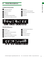
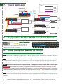
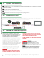
TX-SDI-50
RX-SDI-50
TX-SDI-50 & RX-SDI-50
TX-SDI-50 WyreStorm HDMI Over SDI Dual
Output Transmitter with 2-Way IR, RS232
(50m/164ft)
RX-SDI-50 WyreStorm HDMI Over SDI
Cascading Receiver with 2-Way IR, RS232
(50m/164ft)
Instruction Manual
Thank you for choosing this WyreStorm product.
Please read these instructions carefully before installing to avoid complications later.
Technical Support: [email protected] US: +1 901 384 3575 EMEA: +44 (0) 1793 230 343
1
CONTENTS AND INTRODUCTION
Contents
1
Introduction
2
Features
3
Safety Precautions
4
Package Contents
5
Specification
6
Panel Descriptions
7
Typical Application
8
Copper Core 75Ohm WF100 Coax Cable Distance
9
Initial Connection & Basic IR Control
10 IR/RS232 Control Connection
11 Update RS232 Settings
12 RS232 Connection
13 EDID & SETTING Management
14 Troubleshooting
15 FAQ
16 Maintenance
17 Product Service
18 Mail In Service
19 Warranty
i. Warranty Limits and Exclusions
20 Disclaimer
21 Installation Notes
1.
Introduction
The WyreStorm TX-SDI-50 dual output transmitter and
RX-SDI-50 cascading receiver offer single cable HDMI
over SDI over two synchronous feeds for scalable
extension 1080p HD video, multichannel HD audio and
two-way control up to 50m (164ft) using copper-core 75
Ohm WF100 coax cable.
NOTE: Transmitters (TX-SDI-50) and receivers (RXSDI-50) sold separately due to system scalability,
but both units are required to function as an
extender set.
The TX-SDI-50 features twin-output transmission that
delivers two separate signals of lossless 1080p HD video
@60hz with full 3D support and digital audio to two
distinct display zones over distances up to 50m/164ft
using copper-core 75Ohm coax.
The TX-SDI-50 includes embedded EDID functionality
to manage the EDID handshake between devices to aid
communication and help avoid compatibility issues that
can effect successful signal transmission.
Wide-band, two-way control from source or display
location is possible (when used with the RX-SDI-50
receiver) via IR and RS232 with full support for leading
third party control systems.
The RX-SDI-50 cascading display receiver is designed
to receive transmissions of 1080p HD video, HD audio
and bidirectional IR and serial control from compatible
transmission device, such as TX-SDI-50, as part of an
HDMI over SDI distribution.
Featuring DIP to further manage HDCP, color and signal
settings between connected devices, full 3D compatibility
and 24bit True Color, the RX-SDI-50 includes SDI loop out
that enables up to seven receivers to be daisy-chained
to create larger, multi-location distributions from a single
TX-SDI-50 output.
The combination of dual SDI output fucntionality on the
transmitter to send signals in different directions and SDI
loop out on the receiver for further extension of those
signal enable the creation of highly scalable HDMI over
SDI splitting systems capable of delivering content to
separate locations - with a single transmitter and multiple
receivers used to create total distributions of up to
350m/1148ft from a single SDI output, or 700m/2296ft
over both SDI outputs.
Designed for residential or ProAV applications where
2
Technical Support: [email protected]
US: +1 901 384 3575 EMEA: +44 (0) 1793 230 343
• Conforms to IEEE-568B standards
use• of
coax
to distribute
and control
HD signals is
Each
HDMI
port also supports
DVI signals.
either required due to retrofit installations where existing
• Each
Output
port can be fed
to multiple
displays
(cascaded).
coax
cabling
infrastructure
must
be used,
or preferred
for•itsEnables
low loss
at 4high
frequencies;
vital fortocable/
up to
HDMI
video/audio devices
be independently
switched
throughcable
up to modem
4 HDMI displays
or projectors
satellite
television,
installations
as wellforas
uncompressed
digital distribution.
commercial
applications
such as security/surveillance,
broadcast
television
movie
production
in studio
or
• Each output
able toand
show
any connected
source
simultaneously
location,
videoofconferences,
electronic
teaching,
in fact,
regardless
whether the input
carries HDCP
encryption.
any and wired network area where the extension and
• Refined for Custom Install and Home Theatre Installations.
amplification of SDI transmission is needed.
Part Number CAB-USB-5V
• Fully cascadable
further lengthen
transmission.
•Mini-USB
port fortofirmware
upgrade
•Mounting
brackets
supplied
forcable
secure
*NOTE: ideal
conditions
denote
runinstallation
is within
•IR
emitter,
receiver
and
5v
mains
power
supply included
specified distance range of product, no electrical
interference, the use of straight cable runs with no bends
or kinks and no patch
panels or wall
outlets used.
Please
*Recommended
transmission
conditions
denote
be advised
that
thewithin
presence
of any ofdistance
these factors
in
straight
cable
run
specified
range
installation
may compromise
bandwidth
and use
signal
of your
product,
no electrical
interference
and the
of
strength.
For
longer
transmission
distances,
RS232
control
solid copper core cable with no bends, kinks or midand Ethernet pass-through, please see our full HDBaseT
run connections.
or HDBT Lite range of matrices, transmitters, receivers and
extender sets.
• Reads and copies EDID from connected devices with additional Please be advised that the presence of any of
EDID configuration
customisable
For further
informationthrough
on these
productsDIP
andswitch
othersettings if these factors in your installation may compromise
necessary.
WyreStorm ranges, visit our website or download our
bandwidth and signal strength.
latest
guide
wyrestorm.com
• 2kproduct
resolution
supported.
• Fully 3D compatible – Frame sequential 3D (Blu-ray) and
interlaced stereoscopic 3D (satellite broadcasts etc.)
2.
Features
3.3. Safety
SafetyPrecautions
Precautions
• Supports all high definition resolutions up to and including
1080p and standard video formats.
WARNING
WARNING
•Single
coax
• RS232
port.cable as a substitute for HDMI cable to
reduce
theofrisk
fire, electric
To To
reduce
the risk
fire,ofelectric
shock shock
achieve scaleable long-distance transmission of full HD
or
product
damage:
or
product
damage:
• Choose from 6 switching modes – infrared remote control, front
video,
and
two-way
control LAN and RS232.
panelaudio
buttons,
local
IR, IR call-back,
•Full HD support 1080p@50/60Hz
1. Do not expose this apparatus to rain, moisture, sprays,
• Simple
switching remote
controlup
included,
which can(WF100
also be
•1080p
transmission
distance
to 50m/164ft
1. Dodrips
not expose
thisand
apparatus
to rain,
moisture,
or splashes
ensure that
no objects
containing
learned into a universal remote handset to allow the control of
coax cable) under recommended conditions*
sprays,
or splashes
and ensureincluding
that no cups,
objects
liquidsdrips
are placed
on the apparatus,
multiple devices from one handset.
glasses and
vases.
•24bit color depth
containing
liquids
are placed on the apparatus,
• Fully
for integration
market leading control
systems.
•Fully
3Dcompatible
compatible
- frame with
packing/sequential
(Blucups,this
glasses
vases. space such as
2. including
Do not place
unit inand
a confined
ray),
stereoscopic
(satellite/cable
• 4 xinterlaced
IR 3.5mm mini-jack
ports for
each output to broadcasts)
link IR from
enclosed shelving, cabinets or bookshelves. Ensure the
•Wide-band,
bidirectional
infrared control signal of
2. Dounit
notisplace
this unit
in a confined space such as
control system
to control display
adequately
ventilated.
source from display and display from source locations
enclosed shelving, cabinets or bookshelves. Ensure
• Additional infrared extension port for longer IR connections
3. To prevent the risk of electric shock or fire hazard due to
transmitted together with the HDMI signal
the unit is adequately ventilated.
overheating, do not cover the unit or obstruct ventilation
•
HDMI
v.1.3
•TX-SDI-50: Dual SDI outputs on transmitter provides
openings with material, newspaper, cardboard or
two
synchronous
feedsdepth
that enables signal to be split
3. Toanything
prevent that
the may
risk of
electric
shock
fireunit.
hazard
• Supports
24Bit Colour
restrict
airflow
intoorthe
and fed to different locations
due to overheating, do not cover the unit or obstruct
• Signalling rate of 6.75 Gbps
4. ventilation
Do not install
near external
heat sources
such as
•RX-SDI-50: SDI loop out on receiver allows
openings
with material,
newspaper,
radiators, heat registers, boilers or any device that
• Pack comes to
complete
with 1 x 4x4
Matrix with 19” rack
transmission
be cascaded
by daisy-chaining
up
cardboard or anything that may restrict airflow into the
produces heat such as amplifiers or computers and do
brackets,
4
x
40m
IR
receivers
with
mounting brackets,
to 7 receivers to further lengthen distribution
from aIR
unit.
not place near sources of naked flame.
receivers,
emitters
and a up
Matrix
remote control handset.
single
output
distances
to 350m/1148ft
from a
apparatus
from power
during
lightening
single
TX-SDI-50
SDIincluded
output or
from
4.5. DoUnplug
not install
near external
heatsupply
sources
such
as
Additional
features
on 700m/2296ft
the RX-1UTP-IR-40
storms
or
when
unused
for
long
periods
of
time.
both synchronous outputs RS232 control signal
radiators, heat registers, boilers or any device that
• Transmits one-way signal together with the HDMI signal over a
transmissions supported
heat
suchcable
as amplifiers
orwalked
computers
and
6. produces
Protect the
power
from being
on, pinched
single Cat5e/6/7 cable.
•TX-SDI-50: embedded EDID functionality manages
doornot
place near
sources
of nakedatflame.
restricted
in any
way, especially
plug connections.
• Receivers
capable of 1080p
transmissions
to 40m (131ft)
the
EDID handshake
between
devices toupaid
7. Only use attachments/accessories specified by the
under
ideal
conditions*
communication and help avoid compatibility issues that
5. Unplug
apparatus from power supply during
manufacturer.
can
effect
signal
transmission.
lightening storms or when unused for long periods of
• For
even successful
greater control
and fine
tuning, each receiver features
8. Units contain non-servicable parts - Refer all servicing to
•RX-SDI-50:
DIP Switch
further
manages
HDCP,
time.
a fully adjustable
EQ distance
range
for optimising
thecolor
qualified service personnel.
signal.between connected devices at
andtransmission
signal settings
display location
6. Protect the power cable from being walked on,
Technical Support: [email protected] US: +866
677 0053
EU: +44in
(0)any
1793
230especially
343
4
•HDMI V1.4 supported
pinched
or restricted
way,
at plug
•Each port supports HDMI or DVI signals
connections.
•Auto-adjustment of feedback, equalization and
amplification
7. Only use attachments/accessories specified by the
•HDCP compliant
manufacturer.
•LED indication of power and signal status
•Contains ESD protection technology to safeguard
8. Units contain non-servicable parts - Refer all servicing
against static build-up that can damage circuitry
to qualified service personnel.
Technical Support: [email protected]
US: +1 901 384 3575 EMEA: +44 (0) 1793 230 343
3
FEATURES AND SAFETY PRECAUTIONS
FEATURES AND SAFE
connectors for a single Cat5e/6/7 UTP cable to each display
point for ease of installation.
PACKAGING CONTENTS AND SPECIFICATION
4.
•
Package Contents
1 x TX-SDI-50 Transmitter / 1 x RX-SDI-50 Receiver
•
NOTE: each package contains a single unit NOT both
units - transmitters (TX-SDI-50) and receivers (RX-SDI-50)
are sold separately due to system scalability, but both
units are required to function as an extender set.
5.
•
•
•
1 x Printed user manual for both models - also
downloadable from product web page
2 x 5V/3A DC power supplies (1 per unit)
1 x IR TX emitter - for source connection
1 x IR RX receiver - for display connection (30-50KHz)
Specification
Operating Temperature Range
-5 to +35°C (-41 to +95 °F)
Operating Humidity Range
5 to 90 % RH (no condensation)
Input / Output
TX-SDI-50: 1 x HDMI Output, 2 x SDI output
RX-SDI-50: 1 x HDMI Output, 1 SDI Input, 1 SDI loop Output
Bandwith Signalling Rate
6.75Gbps
Input Resolution Support
1080p/1080i/720p/576p/480p/576i/480i
Input Video Signal
0.5-1.0 volts p-p
Input DDC Signal
5 volts p-p (TTL)
Output Signal Type
HDMI v1.4 + HDCP with full 3D compatibility with frame packing/ sequential (Blu-ray) and
interlaced stereoscopic (satellite/cable broadcasts)
Output Resolution Support
1080p/1080i/720p/576p/480p/576i/480i
Video Format Supported
DTV/HDTV: 640x480p 60Hz, 800x600 60Hz, 1024x768 60Hz, 1280x768 60Hz,
1360x768 60Hz, 1280x960 60Hz, 1280x1024 60Hz, 1400x1050 60Hz, 1440x480i 60HZ,
720x480p 60Hz, 1440x576i 50Hz, 720x576P 50Hz, 1440x576P 50Hz, 1280x720p
50Hz/60Hz, 1920x1080i 50/60Hz, 1920x1080p 24/25/30/50/60Hz, 1280x720p 3D 50/60Hz,
1920x1080i 3D 50/60Hz, 1920x1080p 3D 24Hz
Audio Format Supported
5.1/7.1/stereo audio (Including PCM and non PCM, HD Audio, etc)
Maximum Pixel Clock
148.5 MHz (1080p)
Power Supply
5V/3A DC
Power Consumption
7.5W (TX-SDI-50 Transmitter)
8W (RX-SDI-50 Receiver)
BTU Rating (British Thermal Unit)
N/A
ESD Protection
±8kV (Air-gap discharge)
±4kV (Contact discharge)
Surge Protection
IEC 61000-4-4 (EFT) 40A (5/50ns);
IEC 61000-4-5 (Lightning) 25A (8/20μs)
Dimensions
118mm / 4.6” (W)
157mm / 6.2” (D)
25mm / 1.0” (H)
Weight
0.92Kg / 2.02lb (Pair)
NOTE Specifications are subject to change without notice. Weight and dimensions are approximate.
4
Technical Support: [email protected]
US: +1 901 384 3575 EMEA: +44 (0) 1793 230 343
Panel Descriptions
PANEL DESCRIPTIONS
6.
TX-SDI-50 Transmitter
1
Power input 5V/3A DC
7
EDID switch
2
LED Power indicator
8
USB port for firmware upgrade
3
RS232 port
9
IR TX emitter for source connection
4
HDMI input
10 SDI output 1
5
LED HDMI input status indicator
11 SDI output 2
6
IR RX receiver for display connection
1
2
3
4
5
6
7
8
9
10
11
RX-SDI-50 Receiver
1
SDI input
7
LED SDI input status indicator
2
SDI loop output
8
HDMI output
3
IR TX emitter for source connection
9
RS232 port
4
SETTING DIP switch
10 Power input 5V/3A DC
5
IR RX receiver for display connection
11 LED Power indicator
6
USB port for firmware upgrade
1
2
3
4
5
6 7
8
Technical Support: [email protected]
9
10 11
US: +1 901 384 3575 EMEA: +44 (0) 1793 230 343
5
TYPICAL APPLICATION, COPPER CORE 75 OHM WF100 COAX CABLE DISTANCE AND INITIAL CONNECTION & BASIC IR CONTROL
7.
Typical Application
Key
ir tx
ir rx
SOURCE DEVICE
Coax
ir Link
CABLE
hdmi
Control
System
TX-SDI-50
TRANSMITTER
5V
POWER
RX-SDI-50
RECEIVER
Control
System
5V
POWER
Control
System
RX-SDI-50
RECEIVER
5V
POWER
RX-SDI-50
RECEIVER
5V
POWER
5V
POWER
RX-SDI-50
RECEIVER
8.
RX-SDI-50
RECEIVER
Copper Core 75 Ohm WF100 Coax Cable Distance
Coaxial Wiring Guide
The quality of termination
for every BNC is
essential. Poor terminations leads to intermittent
performance and longer install times.
9.
Coaxial Cable Performance Guide
TX-SDI-50 & RX-SDI-50
0m
10m
20m
30m
40m
50m
60m
70m
80m
90m
100m
0ft
32ft
65ft
98ft
131ft
164ft
197ft
230ft
262ft
295ft
328ft
Initial Connection & Basic IR Control
1 Firmly connect a HDMI source device (such as Blu-Ray, games console, satellite/cable, media server, splitter or
matrix etc.) to the HDMI IN of the TX-SDI-50 transmitter.
2 Connect a good quality, well terminated copper -core 75Ohm WF100 coax cable of no more than 50m/164ft
in length between either of the synchronous SDI OUT ports on the TX-SDI-50 to the SDI IN port of the RX-SDI-50
Receiver.
NOTE If using both SDI OUT ports of the TX-SDI-50, an RX-SDI-50 receiver must be used for each output.
Attention 50m/164ft is the maximum recommended transmission distance over coax using this SDI
equipment and denotes perfect transmission conditions - including straight cable runs with no electrical
interference, bends, kinks and joins etc. If any of the above are a factor in your installation, transmission
range may be affected – take care to avoid where possible.
3
Firmly connect the HDMI sink (LCD/LED/Plasma display / digital projector) to the HDMI OUT of the RX-SDI-50
receiver.
6
Technical Support: [email protected]
US: +1 901 384 3575 EMEA: +44 (0) 1793 230 343
4
For control of the source from display zone, connect the IR TX emitter from the TX-SDI-50 transmitter to the
infrared receiver window of the source using the adhesive backing - you may need to adjust the position of the emitter
eye on the source for best results.
When happy with the placement, press down firmly to ensure secure attachment of the emitter to the source.
HINT You can locate the IR sensor of devices by shining a flashlight onto the front of the device - the
sensor should be a small round diode located behind the facia. If in doubt, please consult the device
manufacturer handbook.
5
At the display zone, connect the IR RX receiver cable from the RX-SDI-50 receiver to the display, ensuring clear
line of IR sight with he remote handset used to control. We recommend discrete placement of the IR RX eye using the
adhesive backing, pressing down firmly to secure attachment.
6
If daisy-chaining receivers , connect another coax cable of no more than 50m/164ft in length from the SDI OUT
port of the RX-SDI-50 receiver to the SDI IN of another RX-SDI-50 receiver unit to enable signal pass-through.
NOTE Whereas the SDI loop out function on receivers enables the cascading of up to seven units from each
of the transmitter SDI outputs, IR and RS232 pass-through functionality is limited to the first unit connected
to each output only.
7
Connect the 5V DC power supplies included to both TX-SDI-50 and RX-SDI-50 and power on source, transmitter,
receiver and display.
8
Ensure the POWER and STATUS indicators are lit on both transmitter and all receivers used to confirm all units are
powered and a signal is being passed between them.
Attention If you fail to receive a signal, check LED indicators are lit before checking power supply, all
attached cables and source/display devices for correct connection and operation.
10.
Bidirectional IR/RS232 Control Connection
1
For bidirectional control of the source from display zone and display from source zone, connect the IR TX emitter
from the TX-SDI-50 transmitter to the infrared receiver window of the source using the adhesive backing - you may
need to adjust the position of the emitter eye on the source for best results. Ensure emitter is firmly attached over IR
sensor - we recommend pressing down firmly to secure the adhesive backing.
HINT If unsure of positioning, IR sensors can be located on devices by shining a flashlight onto the facia
of the device - the IR sensor should be identifiable as a small round sensor behind the panel. If in doubt,
please consult the device manufacturer handbook.
2
If using an RS232-based control system, connect an IR Link Cable from the IR RX port of the TX-SDI-50
transmitter to your control system and insert cables into the RS232 ports to enable serial control.
3
At the display zone, connect the IR RX receiver cable between the RX-SDI-50 receiver and the display, ensuring
clear line of IR sight with he remote handset used to control. We recommend discrete placement of the IR RX eye on
the display, pressing down firmly using the adhesive backing.
4
Connect an IR TX emitter from the RX-SDI-50 receiver to the infrared receiver window of the display device using
the adhesive backing - again, the position of the emitter may need to be adjusted for best results. Ensure emitter is
firmly attached over IR sensor - we recommend pressing down firmly to secure the adhesive backing.
Technical Support: [email protected]
US: +1 901 384 3575 EMEA: +44 (0) 1793 230 343
7
BIDIRECTIONAL IR/RS232 CONTROL CONNECTION
NOTE We strongly recommend using the supplied mounting brackets to secure both transmitter and
receiver. Any sudden movement of devices can lead to loss of picture/sound if connections become loose
or strained, resulting in unnecessary service call backs.
UPDATE RS232 SETTINGS, RS232 CONNECTION AND EDID & SETTING MANAGEMENT
11.
Update RS232 Settings
1 To update firmware for your device, simply connect a Serial-to-mini USB cable from the ISP port of the TX-SDI-50
/ RX-SDI-50 to a computer
2
Run VS010 are X Firmware Update batch file.
3
When complete, remove the Serial-to-mini USB cable
NOTE Devices will not transmit or receive signals while updating firmware.
12.
RS232 Connection
To allow serial commands to be sent between transmitting and display devices, simply connect serial cables between
your control system and your display via the phoenix ports on the SDI extender set.
Display Output
TX-SDI-50
TRANSMITTER
RX-SDI-50
RECEIVER
Blu-ray
hdmi
hdmi
Coax
rs232
Control
System
rs232
CONTROL SYSTEM
13.
EDID & SETTING Management
Distribution of HD signals through devices requires
mutual communication or ‘handshake’ between source
and display. If there is any disparity between the two,
successful transmission becomes problematic.
ideally with all power cables and HDMI leads and
coax cables removed to guard against electrostatic
build up that may damage your system.
Manual DIP adjustment is included on both models, with
the TX-SDI-50 featuring embedded EDID management
to negotiate the EDID handshake between source and
display devices and the RX-SDI-50 offering further
management of HDCP, color and signal settings at
display location - all of which aid communication between
connected devices and help avoid compatibility issues
that can effect successful signal transmission.
If compatibility or transmission issues arise during
installation, check the settings on your connected
devices and adjust the DIP settings as required.
DO NOT HOTSWAP your cables when changing DIP
SETTINGS.
Transmitter
ON
DIP (DEFAULT) Video Auto-Mode
(recommended setting): SDI signal
automatically detected and bypasses
output, non-SDI signals processed by FPGA
Receiver
(DEFAULT) Audio Auto-Mode (recommended setting)
SDI audio (PCM 48k) signal automatically detected and
bypasses output, non-SDI signals processed by FPGA
Attention Changes to DIP settings become
effective upon powering ON the units. Changes
to settings should be made with all devices OFF,
8
Technical Support: [email protected]
US: +1 901 384 3575 EMEA: +44 (0) 1793 230 343
Receiver
Process Mode (not recommended): any connected source
processed by FPGA, regardless of signal
Transmitter
ON
DIP
EDID Copy Trigger (Note 1)
Receiver
Non-encryption Output: disables HDCP
signal encryption output
Transmitter
ON
DIP
(DEFAULT) 1080P Stereo EDID / EDID
Copy Trigger (Note 1)
Receiver
(DEFAULT) Output HDCP: dictated by sink device
Transmitter
ON
DIP
Reserved for future use - no function
Receiver
Color Detect Mode: colour depth dictated
by sink device
Transmitter
ON
DIP
Reserved for future use - no function
Receiver
(DEFAULT) 24bit Color Output
Transmitter
ON
DIP
EDID Copy:
copies EDID from sink device to the input
port. Note: EDID Copy Trigger mode must
be activated for this function
Receiver
Reserved for future use - no function
Transmitter
ON
DIP
1080p 3D video, 7.1 Audio EDID
Receiver
Reserved for future use - no function
Transmitter
ON
DIP 1080p video, 7.1 Audio EDID
Receiver
Reserved for future use - no function
Technical Support: [email protected]
Transmitter
ON
DIP (DEFAULT) 1080p 3D video, Stereo Audio
EDID
TROUBLESHOOTING
Transmitter
ON
DIP Process Mode (not recommended): any connected source processed by FPGA,
regardless of signal
Receiver
Reserved for future use - no function
Note1:
(DEFAULT) 1080p stereo EDID is the factory default setting
(OFF). Switching to ON activates the EDID COPY TRIGGER
mode, which sends a command to the MCU for the
Transmitter to copy EDID from the Receiver.
Note: this is not an ‘Auto-copy’ setting.
Following an initial change of setting to the ON position,
returning the switch to OFF will not return to DEFAULT 1080p
Stereo EDID. Instead, both ON and OFF positions will ‘Trigger’
the command to be sent to the MCU for the Transmitter to
copy EDID from the receiver. Toggling between settings will
resend the trigger command to copy EDID.
To reset to 1080p Stereo, connect a display set to output
1080p 2CH audio and trigger the EDID Copy or change EDID
DIP settings to 1080p 3D Stereo EDID.
14.
Troubleshooting
Generally, the majority of HD distribution installation
issues are either caused by minor connection
errors, communication problems between devices,
or when the transmission of high signal bandwidth
is attempted using insufficient cable. Should you
encounter any technical difficulties when installing
and configuring the matrix, we are confident
solutions can be found by working through the
following troubleshooting checklist before seeking
alternative technical support.
No Picture or Poor Quality Picture
1) Power – are your SDI transmission and receiving
devices powered with correct LED indication? All units
should have their own power source connected ie. 5v
for most 50m/164ft for SDI devices – Please use power
supplies included.
Are all sources definitely powered and firmly connected?
2) If possible, always use test equipment prior to
installation and to troubleshoot any problems. See
WyreStorm system testing range at wyrestorm.com
US: +1 901 384 3575 EMEA: +44 (0) 1793 230 343
9
TROUBLESHOOTING
3) Check sink device supports HDCP, is switched to the
correct source input mode and is compatible with the
receiver - if any issue is suspected, replace sink device
with another model.
4) Distance – Is the cable too long for the signal to be
transmitted effectively? The transmission technology used
within the transmitters and receivers allows 1080p up
to 50m/164ft so make sure the cable distance matches
the project requirements and is well within the maximum
transmission distance of the signal.
Note: If approaching the limits of the transmission
capabilities, transmission should be extended by using
another extender set to ensure the signal reaches its
destination effectively.
5) Cable Joins - Joins in the cable run or coax
connectors can impact on signal strength, resulting in
reduced transmission that may manifest itself in incorrect
picture quality, picture dropping out or a complete lack of
picture
6) Cable Choice and Signal Reduction – Are stranded
patch leads being used as interconnects between patch
panels or wall outlets? CCA ( copper Clad aluminum
) cables being used? These can reduce transmission
rates by up to 40% – we recommend solid core straight
through with minimum connections used wherever
possible.
7) Correct connection – It may seem obvious but
double check all coax, HDMI, power and IR cables are
connected to the correct ports.
8) Electrical interference – SDI transmission is
susceptible to interference from mains cable and electrical
switching equipment (relays and lighting dimmers). The
location of cables and devices should be considered
prior to installation - could any form of interference
be generated? If so, attempt to remove the source of
electrical interference or move the cable run to decrease
the effects of the interference.
9) Is a picture achieved when connecting the source
directly to the display? If not then the problem could lie
with the input or output device rather than the means of
distribution i.e. the cable, receiver or matrix itself.
Technical Support: [email protected]
11) Picture speckles/HD ‘noise’ – represents a poorly
established signal that may be caused by poor quality
coax or excessive HDMI cable lengths.
12) HD Noise (NO image) – may be an HDCP issue
between the source and display but poor cabling can also
cause this due to poor communication.
13) Blu-ray: 3D – is the equipment used 3D enabled/
compatible? Is a 3D disc being played in a 3D enabled
Blu-ray player or through a compatible AV receiver?
14) color distortion – a pink or green screen indicates
an incompatibility between color spacing formats - the
commonly used RGB or YUV used by older displays.
Some sources allow switching between RGB and YUV
which may solve any color problems. If not, try changing
the HDMI cable between the source and the extender set
to rule out defective cabling.
No Sound or Poor Quality Audio
Audio is transmitted within the video signal – there is no
separate audio track – so generally a problem with sound
will be accompanied by a problem with picture. However,
if technical issues with audio are experienced, the cause
is typically communication between sources, displays
and/or AV receiver settings.
Note: Even a fraction off can be the difference between
a perfect picture and a blank screen. Double check all
connections are firmly made in the correct ports.
10
10) HDMI lead condition and quality – HDMI cables
and connectors are delicate and can be damaged much
easier than component or coax cable. Furthermore,
lead quality varies dramatically, particularly in lower price
brackets. Swap HDMI leads and check operation –
damage to or quality of your leads could be the problem.
If in doubt, swap them over. Always take care inserting
and extracting your HDMI from extender ports so as not
to damage the connectors or ports.
1) Have specific speaker sets or zones been
enabled? Some AV receivers allow individual speaker
selections assigned to specific zones in the set up so
check the speakers used are fully connected to the
amplifier and correctly assigned within the system set up.
It may be an EDID issue in that the source reads the audio
EDID from the display and only requests two channel
audio and EDID copy from the AVR may be required or
use an embedded EDID in the SDI extenders. Note: If
problems are experienced when an AV receiver is used,
the cause is usually the settings of the AVR itself. Refer to
the AVR manufacturer’s guidelines on the correct settings
to use for your requirements.
US: +1 901 384 3575 EMEA: +44 (0) 1793 230 343
3) Do all the local sources work through the
AV receiver? Check the operation of each source
individually.
5) Coax Termination Issues – ensure cables and
coax terminations are correct and in good condition at
both transmitter and receiver ends to see if control is
established. If so, a possible re-termination of the cable
could remedy the problem.
6) Are WyreStorm emitters and receivers being
used? The use of third party products/magic eyes may
not be compatible. Always use WyreStorm components
included with your purchase or check compatibility of third
party control systems with your WyreStorm dealer.
7) If problems persist, swap out the IR emitters and
receivers to rule out faults with the units themselves. Use
emitters you know are fully operational to test working
condition.
Bandwidth
1) If using a graphics-based source (such as a PC/Mac/
media server), make sure the source resolution is set to
a maximum of 1080p, 50Hz. Higher resolutions available
for graphics-based systems require higher bandwidth
that may affect transmission of signals as well as
incompatibility with devices.
15.
IR
1) Check emitters at the IR TX transmitter end
and receivers at the IR RX receiver end – are they
connected to the correct ports on the matrix and display
receiver.
2) Is the emitter correctly positioned on the source?
Fix the emitter directly over the infrared sensor of the
source and attach using the adhesive backing. Note:
Locate the infrared source sensor by using a flashlight to
find the sensor within the fascia of the source display. If
necessary, secure the emitter over the sensor with a small
amount of contact adhesive.
3) Is the remote handset powered and sending a
signal? Note: IR is invisible to the naked eye, so use a
digital camera/ phone camera to check the remote signal
– point the camera at the remote control when pressing
a button. The remote transmitter can be seen flashing to
indicate a signal being sent. Replace batteries if flashing is
not seen on the digital camera screen.
4) IR dropout issues can be due to exterior influences
emitting infrared radiation that can interrupt IR signals.
Ensure emitters and receivers are away from the following
causes of IR interference.
• Direct sunlight, Fluorescent lighting (on cold start up)
• Halogen lighting
Technical Support: [email protected]
• Plasma screens
FAQ
How far can the signal travel?
Under perfect transmission conditions WyreStorm SDI
extender set will operate at 50m (@1080p). Perfect
conditions denotes no electrical interference, straight
cable runs with no bends or kinks and no patch panels
or wall outlets. If some of the above are factors in your
installation then signal strength and bandwidth can be
compromised.
Should a cable run approach the upper limit of the
receiver capabilities, the signal can be boosted by
connecting an additional RX-SDI-50 as an in-line repeater
up to 7 times.
What about 3D?
All WyreStorm products will pass-through a 3D Blu-ray
signal.
How do I control the sources?
All of our HDMI distribution products support IR passthrough from point-to-point extender sets to AMP and
HDBaseT matrices. Our PP and HDBaseT matrix range
(Cat5e/Cat6) has IR pass-through from each of the
outputs and has discrete IR outputs at the switch end,
meaning you can have multiple identical sources yet the
IR would be routed only to the applicable source.
Do I need power at the TV end?
Yes. This product requires its own 5v local power at
display zones to operate. WyreStorm PoH enabled
US: +1 901 384 3575 EMEA: +44 (0) 1793 230 343
11
FAQ
2) Consistency of audio output between devices – Is
there any discrepancy between the audio output of the
source, the audio or zonal settings of the AV receiver and
the speaker configuration used needed for successful
audio replication? If outputting 7.1, make sure all devices
connected are also outputting 7.1
Note: Occasionally with some sources, the device
settings allow the specification of audio output through
a TV or an HDMI port. If using an AV receiver, check the
HDMI output option is selected.
MAINTENANCE AND PRODUCT SERVICE
devices require no power supply at the TV end by
drawing power from a PoH matrix or PoH transmitter. See
wyrestorm.com for details on our PoH range.
Are WyreStorm products compatible with HDMI 1.4?
HDMI 1.4 refers to a list of ‘features’ that a device is
capable of supporting, including Ethernet channel, return
audio channel, 3D etc. Due to the continuously evolving
nature of the technology, HDMI Licensing LLC have now
decided to simplify terminology by testing and referring to
cable in terms of STANDARD or HIGH-SPEED rather than
in generations 1.3, 1.4 etc. • STANDARD (or “category
1”) HDMI cables perform at speeds of 75Mhz or up
to 6.75Gbps, which is the equivalent to a 720p/1080i
signal – These HDMI cables are NOT recommended.
• All WyreStorm equipment support HIGH-SPEED
(or “category 2”) HDMI cables that have been tested
to perform at speeds of 340Mhz or up to 10.2Gbps,
which is the highest bandwidth currently utilised over
an HDMI cable and can successfully handle 1080p
signals including those at increased color depths and/
or increased refresh rates from the Source. High-Speed
cables are also able to accommodate higher resolution
displays, such as WQXGA theater monitors (resolution of
2560 x 1600).
What about screens with different resolution
capabilities?
When sending a signal point to point a TV will
communicate its capabilities to the source, with the
source subsequently outputting a suitable signal
compatible with the display (i.e. 1080p Stereo audio).
If you were to use this extender set with three 1080p
screens and one 1080i screen, the resultant image would
be 1080i across all screens. The receivers do not scale
per output but instead negotiate with the source a signal
that all screens are capable of supporting.
How does the Transmission device handle HDCP?
HDCP (High Definition Copyright Protection) is a feature
built in to HDMI devices to prevent theft of or illegal
distribution of HD content. Unlike competing products,
WyreStorm equipment are legal and comply with HDCP
regulations.
They do this by assigning a “key” to any display
connected to the device. HDCP “keys” are assigned to a
display when connected to a HDMI device normally. This
doesn’t change when connecting to an extender, receiver
or matrix switch; rather keys are duplicated or more are
assigned.
12
Technical Support: [email protected]
I can get 1080i but not 1080p at a TV location
Firstly ensure that both the source is capable of outputting
1080p and that the TV is Full HD 1080p screen. If this
is the case then the extender set may require an EDID
setting using the DIP switches. This useful feature
provides a successful “send and receive” to ensure swift
and stable EDID negotiation between the source and
display. See Troubleshooting section for more tips on
problem solving.
I cannot get a signal from my A/V receiver along a
Cat5e extender set
Check to ensure that the A/V Receiver isn’t adding CEC
(HDMI Control Protocol) to the outgoing signal, this can
sometimes have an effect on the HDMI signal.
16.
Maintenance
Clean this unit with a soft, dry cloth only. Never use
alcohol, paint thinner or other harsh chemicals.
17.
Product Service
1. Damage requiring service: This unit should be
serviced by a qualified service personnel if: • The DC
power supply or AC adaptor has been damaged.
• Objects or liquid have gotten into the unit.
• The unit has been exposed to rain.
• The unit does not operate normally or exhibits a marked
change in performance.
• The unit has been dropped or the cabinet damaged.
2. Servicing Personnel: Do not attempt to service the
unit beyond that described in these operating instructions.
Refer all other servicing to authorised servicing personnel.
3. Replacement Parts: When parts need replacing,
ensure parts approved by the manufacturer are used
– either those specified by the manufacturer or parts
possessing the same characteristics as the original parts.
Be aware – unauthorised substitutes may result in fire,
electric shock, or other hazards and will invalidate your
warranty.
4. Safety Check: After repairs or service, ask the service
personnel to perform safety checks to confirm the
unit is in proper working condition. When shipping the
unit, carefully pack and send it prepaid, with adequate
insurance and preferably in the original packaging. Please
include a document or letter detailing the reason for return
US: +1 901 384 3575 EMEA: +44 (0) 1793 230 343
18.
accident, misuse, abuse, neglect, mishandling,
misapplication, alteration, incorrect installation, set-up
adjustment, implementation of/to consumer controls,
improper maintenance, power line surge, lightening
damage, modification, service by anyone other than
a manufacturer-approved service center or factoryauthorised personnel, or damage attributable to acts of
God.
Mail-in-service
If repair is required during the limited warranty period,
the purchaser will be required to provide a sales receipt
or other proof of purchase, indicating date and location
of purchase as well as the price paid for the product.
The customer will be charged for the repair of any unit
received unless such information is provided.
19i.
2. There are no express warranties except as listed under
“limited warranty coverage.” The warrantor is not liable
for incidental or consequential damage resulting from the
use of this product or arising out of any breach of this
warranty.
Warranty
Should you feel your product does not function
adequately due to defects in materials or workmanship,
WyreStorm (referred to as “the warrantor”) will, for the
length of the period indicated below (starting from the
original date of purchase) either:
For example: damages for lost time, the cost of having a
person/persons remove or re-install previously installed
equipment, travel to and from service location, loss of or
damage to media, images, data or other recorded/stored
content. The items listed here are not exclusive, but are
for illustration only.
a) Repair the product with new or refurbished parts.
or
b) Replace it with a new or refurbished product.
Parts and service not covered by this limited warranty
are not the responsibility of the warrantor and should be
considered the responsibility of the individual.
Limited warranty period:
All WyreStorm products are covered by a too year PARTS
and labor warranty. During this period there will be no
charge for unit repair, replacement of unit components or
replacement of product if necessary.
The decision to repair or replace will be made by the
warrantor. The purchaser must mail-in the product during
the warranty period. This limited warranty only covers the
product purchased as new and is extended to the original
purchaser only. It is non-transferable to subsequent
owners, even during the warranty period. A purchase
receipt or other proof of original purchase date is required
for the limited warranty service.
19ii.
Warranty Limits &
Exclusions
1. This Limited Warranty ONLY COVERS failures due
to defects in materials or workmanship and DOES
NOT COVER normal wear and tear or cosmetic
damage.
The limited warranty also DOES NOT COVER damage
that occurs in shipment or failures caused by products
not supplied by the warrantor, failures resulting from
Technical Support: [email protected]
US: +1 901 384 3575 EMEA: +44 (0) 1793 230 343
13
MAIL-IN-SERVICE, WARRANTY AND WARRANTY LIMITS & EXCLUSIONS
and include a daytime telephone number and/or email
address where you can be contacted.
DISCLAIMER AND INSTALLATION NOTES
20.
Disclaimer
21.
Installation Notes
WYRESTORM PUBLICATION DISCLAIMER
The material contained in this document consists of
information that is the sole property of WyreStorm. This
document is intended to provide information to allow
interfacing to the relevant WyreStorm equipment by third
party products.
WYRESTORM IS NOT RESPONSIBLE FOR
MALFUNCTIONS AND/OR THE IN-OPERABILITY
WHICH MAY BE CAUSED BY THE APPLICATION
OF THIS INFORMATION, WHETHER EXPECTED OR
NOT.
WyreStorm reserves the right to change software, control
codes and specifications without notice.
WyreStorm will not be liable for any use of this information
or any changes it may make to those products. The use
of this information constitutes an agreement by the user
to these limitations and exclusions.
14
Technical Support: [email protected]
US: +1 901 384 3575 EMEA: +44 (0) 1793 230 343
INSTALLATION NOTES
Technical Support: [email protected]
US: +1 901 384 3575 EMEA: +44 (0) 1793 230 343
15
wyrestorm.com
WyreStorm Offices
US Office: 6991 Appling Farms Parkway, Suite 104, Memphis, TN 38133
Tel: + 901 384 3575 Fax: + 901 384 3574
Unit 22, Ergo Business Park, Swindon, Wiltshire, SN3 3JW UK
Tel: +44 (0) 1793 230 343 Fax: +44 (0) 1793 230 583
WyreStorm Technical Support
US: + 901 384 3575
UK:- +44 (0) 1793 230 343
Email: [email protected]
WyreStorm Technologies reserve the right to change physical appearance or technical specification of this product at any time.
Visit wyrestorm.com for the latest information on products..
REV0415A


![XL[2] Technical Reference – Hardware](http://vs1.manualzilla.com/store/data/005956150_2-4515f3a1b925b4223206cf04092ab5bd-150x150.png)