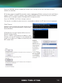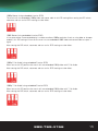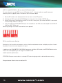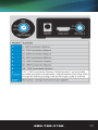
1
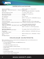
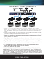
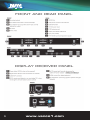
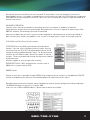
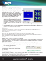
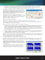
HDMI® MATRIX OVER UTP
4X4 QUICK INSTALL BASIC
OVER SINGLE UTP
PRODUCT MANUAL
Vanco Part Number
VPW-280755
www.vanco1.com • 888.769.4156
DEAR CUSTOMER
Thank you for purchasing this product.
For optimum performance and safety, please
read these instructions carefully before
connecting, operating or adjusting this product.
Please keep this manual for future reference.
This product is 100% inspected and tested in the United States
to verify HDMI performance parameters.
WARNING
1. Do not expose this unit to water, moisture,
or excessive humidity.
2. Do not install or place this unit in a built-in
cabinet, or other confined space without
adequate ventilation.
3. To prevent risk of electrical shock or fire
hazard, due to overheating, do not obstruct
unit’s ventilation openings.
4. Do not install near any source of heat,
including other units that may produce heat.
6. Only clean unit with a dry cloth.
7. Unplug unit during lightening storms, or
when not used for an extended period
of time. A surge protector is strongly
recommended.
8. Protect the power cord from being walked
on or pinched, particularly at the plugs.
9. Use unit only with accessories specified by
the manufacturer.
10.Refer all servicing to qualified personnel.
5. Do not place unit near flames.
CAUTION
HDMI is a very complex technology requiring continuous authentication of the signal and the same
video resolution and audio settings on all electronic equipment in the system. When there are multiple
sources and displays, the video resolution and audio setting on all connected units must be adjusted
to correspond with that of the display having the lowest video and audio capability.
2
www.vanco1.com
FEATURES
Vanco Powered by Wyrestorm Quick Install 4x4 Matrix over UTP with RS-232 is an HD switching and extension
system that comprises of a 4 input/4 output HD Matrix together with included 4 display receivers. Have 4 sources
displayed simultaneously on any display or have a single source duplicated on multiple displays, flexibility for the
perfect solution. Simple plug and play solution that allows each output with the ability to extend HDMI signal up
to 131 feet over a single category 5e or 6 cable. With an output bandwidth of 6.75 Gbps, the VPW-280755 is
capable of full 1080p HD video and HD multi-channel audio distribution with simple control using the front panel or
remotely via IR Receivers at display locations. Also features EDID management system, which allows and encourages
device communication compatibility for seamless integration. Includes RS232 connectivity for firmware updates
or third party integration for control and switching. For the quickest, most convenient and cost effective means of
transmitting and controlling full, uncompressed 1080p HD video and HD audio, the VPW-280755 is a solid choice for
any application.
Vanco Powered by WyreStorm Quick Install Basic HDMI®
4x4 Matrix over UTP
Part # VPW-280755
yy Enables up to 4 HDMI video/audio devices to be
independently switched to 4 HDMI displays or projectors
for uncompressed digital distribution up to 40m (130ft)
over a single Cat5e/Cat6 cable
yy Each output is able to show any connected source
simultaneously regardless of whether the input carries
HDCP encryption
yy Designed work seamlessly together for complete
compatibility and full management of handshakes, screen
resolutions and HD signal distribution to each display
point, whether in a residential or commercial environment
yy Protection against ESD (electrostatic discharge) included
within the receiver units to further stabilize transmission
yy Receivers feature LED indicators for clear power and video
signal selection
yy RS232 port
yy Choose from 6 switching modes – infrared remote control,
front panel buttons, local IR, IR call-back, LAN and RS232
yy Simple switching remote control included, which can also
be learned into a universal remote handset to allow the
control of multiple devices from one handset
yy Fully cascadable so multiple units may be combined to
create a larger HD distribution
yy Fully compatible for integration with market leading
control systems
yy Reads and copies EDID from connected devices with
additional EDID configuration through customizable DIP
switch settings
yy 4 x IR 3.5mm mini-jack ports for each output to link IR
from control system to control display
yy Simplified ports - Input: HDMI – Output: integrated RJ45
connectors for a single Cat5ei/6/7 UTP cable to each
display point for ease of installation
yy Conforms to IEEE-568B standards
yy Each HDMI port also supports DVI signals
yy Fully 3D compatible – Frame sequential 3D (Blu-ray) and
interlaced stereoscopic 3D (satellite broadcasts etc.)
yy Supports all high definition resolutions up to 1080p
yy 2k resolution supported
yy Receivers includes additional infrared extension port for
longer IR connections
yy HDMI v.1.3
yy Supports 24Bit Color depth
yy Signaling rate of 6.75 Gbps
yy Pack comes complete with 1 x 4x4 Matrix with 19”
brackets, 4 x 40m IR receivers with mounting brackets, IR
receivers, emitters and a Matrix remote control
yy 12V DC, UL Listed Power supply for 4x4 matrix
yy 5V DC, UL Listed Power Supplies for Receivers (4 total)
yy For even greater control and fine tuning, each receiver
features a fully adjustable EQ distance range for optimizing
the transmission signal
yy 4x4 Matrix Dimensions: 17.25” W x 2.05” H x 9.25” D
yy Receivers Dimensions: 2.4” W x .09” H x 4.5” D
888.769.4156
3
SPECIFICATIONS
Dimensions (WxHxD): ................................................ MATRIX: 440mm/17.3” x 52mm/2.05” x
235mm/9.25” - RECEIVERS: 60mm/2.4” x 115mm/4.5” x 23mm/0.9”
Weight (Kg): ............................................................. MATRIX: 2 Kg/4.4lbs RECEIVERS: 0.15 Kg/0.3lbs
Operating Temperature Range: .................................... -5 to +35°C (+23 to +95 °F)
Operating Humidity Range: ......................................... 5 to 90 % RH (no condensation)
Video Amplifier Bandwidth: ......................................... 6.75Gbps
Input Video Signal: ..................................................... 0.5-1.0 volts p-p
Input DDC Signal: ....................................................... MATRIX: 12 volts p-p (TTL) - RECEIVERS: 5 volts p-p
(TTL)
Maximum Single Link Range: ....................................... 1080p 24bit color depth
Transmission distance: ............................................... 1080p signal up to 40m / 131ftft (Under perfect
transmission conditions including straight cable runs with no electrical interference, bends, kinks, patch panels
or wall outlets.)
Video Format Supported:............................................. VESA: 640x480, 800x600,1024x768,
1280x1024,1600x1200, 1920x1200 DTV/HDTV: 480i/576i/480p/576p/720p/1080i/1080p
Output Video:............................................................. HDMI v1.2, HDMI v1.3 + HDCP (Output display
mirrors the Input source)
Audio Format Supported: ............................................ Fully supports Dolby True HD and DTS-HD (mirrors
input audio source to the output display)
Power Supply: ........................................................... MATRIX: 100-240V AC - RECEIVERS: 5VDC (mains
or USB 5V power adapter)
Power Consumption: .................................................. MATRIX: 22 Watts (max.) - RECEIVERS: 1.5 Watts
(max.)
Rack Space Required: ................................................ MATRIX: 1U
PACKAGE CONTENTS
Before attempting to use this unit, please check the packaging and make sure the following items are
contained in the shipping carton:
• (1) Vanco Powered by Wyrestorm VPW-280755 Matrix Unit
• (4) Display receivers
• (1) 12VDC Power Supply for Matrix Unit
• (4) 5VDC Power Supplies for display receivers
• Product Manual
• Mounting brackets with screws for both Matrix Unit and display receivers
• (1) IR Remote
• (1) IR RX Extension Cable
• (4) IR TX emitters (small for input source)
• (4) IR RX receivers (larger for displays)
4
www.vanco1.com
CONNECT AND OPERATE
Cable Box
BluRay® Player
Game
Console
Apple TV
1. Connect up to 4 sources such as a Blu-Ray Player, game console, A/V Receiver, Cable or Satellite
Receiver, etc. to the HDMI inputs on the unit. Do not hotplug! Insert and extract cables carefully with the
power SWITCHED OFF. Connecting and disconnecting while the unit is powered can result in damage to
circuitry.
2. Connect the output UTP output ports, starting with output 1, to the included display receivers (using well
terminated or pre-terminated Cat5e/6 cables no longer than 131 ft)
3. Connect the output HDMI ports of the display receivers to high-definition displays such as an HDTV or HD
projector that use HDMI inputs. Note that high-speed HDMI cables are recommended for the distances
that are required for each connection.
4. Plug in IR transmitters to the back of the Matrix Selector Switcher unit (IR TX), the transmitters are
labeled IR TX, place in front of the IR receiver of the source, ensure that each emitter is placed in front of
the IR receiver eye. Double-sided adhesive tape provided.
5. Plug in IR receivers to the port of the display receiver baluns (IR RX), the receivers are labeled IR RX, use
provided double-sided adhesive tape to stick emitters at each display at a desired place that will receive a
remote signal.
6. For power, plug in the source first, followed by the Vanco Powered by Wyrestorm Matrix Selector
Switcher (power supply included), followed by each output connected.
7. Power on each device in the same sequence.
At this point each display connected should display the assigned source (input 1 at default when powered
on initially), scroll through each of the sources on each display to ensure everything is in working order. Use
included IR remote at each display receiver to test switching function between sources and IR function itself.
If a display is having difficulty receiving a signal, access the display’s menu and adjust the resolution (lowest to
highest until signal is displayed). A 24 Hz vertical refresh rate may work better than 60 Hz or higher. If the IR
remote function is not responding, check the emitters to ensure they are placed correctly and are plugged into
the correct IR jacks on the Matrix Selector Switcher unit.
888.769.4156
5
FRONT AND REAR PANEL
DISPLAY RECEIVER PANEL
6
www.vanco1.com
BASIC OPERATION
Basic switching of various source inputs to output displays can be achieved via the front panel control of the
VPW-280755.
Outputs are numbered 1 – 4 with an input select button to the left. Repeated pressing of the select button of
a specific output scrolls through the HDMI input devices connected to the matrix, with the corresponding LEDs
illustrating when a device has been selected for that particular output. The chosen input will automatically
store for the output so, even when the matrix is powered off and on, on resumption the last selected input/
output combination will remain.
ATTENTION Users will notice a brief flicker on screen when switching between inputs/outputs – this is normal
for this model and represents the matrix resetting device HDCP settings to allow communication from a
different device.
For constant HDCP when switching with no noticeable screen resets, see Wyrestorm PRO, Pro Plus and
HDBaseT matrix ranges. See wyrestorm.com for more information
The same basic functions can also be accessed via the remote
control. Operation of the handset is the same regardless of
location – locally (source/IR emitter) or remotely (display/IR
receiver).
Simply toggle through the input sources connected to the matrix by
either pressing the left/right arrow buttons or buttons numbered
1 – 4 for each output.
IR Call-back of Matrix and Source Devices
The VPW-280755 is not only a switcher and extender of multiple
HDMI signals to multiple HDMI receivers located remotely, it
also passes IR control signals through the IR call-back system to
the matrix and HDMI sources for full, independent control of all
connected inputs from output locations using your remote handset.
888.769.4156
7
This is accomplished by placing a series of IR Emitters on
source devices you wish to control and IR Receivers at all
output locations you wish to control from to enable the IR
control signal to be delivered via single Cat5e/6/7 cable
connecting the two.
1. At Matrix end: Insert the 3.5mm jacks of the IR TX
Emitters included with the unit into the IR TX Emitter
ports at the rear of the matrix according to input. The
IR signal is added to the HDMI of the input device so, for
example, if the user is watching Blu-ray on input 3, the
IR signal will be directed through the IR TX3 socket to
control the device.
As each IR TX port is allocated to an individual HDMI
input port, if the user is unable to establish IR control
of the device, care should be taken to check that, firstly,
the IR emitter and HDMI input ports match (Input 1-TX1,
Input2-TX2 etc.) with plugs secured in correct ports,
and secondly, that the IR TX emitter sensors are firmly
attached directly to the front of inputs and covering
infrared sensor windows of the source devices.
Some later adjustment may be needed to the location
of the sensor to achieve the best performance results sometimes moving the sensor to different areas on the
source can improve IR performance.
HINT infrared receiving areas of devices can be located
by shining a flashlight onto the front of the device – the
sensor should be able to be seen through the plastic as a
small, round object inside.
2. At display end: Insert the IR RX Receiver jack into
the IR RX port of the display receiver baluns, with the IR
receivers themselves placed in clear view on or near the
displays to receive an infrared signal from the remote
handset used to control inputs.
Fasten firmly to the surface to avoid displacement.
ATTENTION Misplaced or poorly secured IR Emitters and
Receivers may result in intermittent IR control signals
passed to and from the matrix. Check your placement and
adjust if necessary.
HINT If problems are encountered controlling devices
remotely, check IR TX Emitters and IR RX Receivers are
correctly positioned and connected to sources, displays
and display receivers, with all devices fully powered and
the matrix set to IR call-back enabled and IR TX Switch
mode activated. See COM CTL section for Call-back
enablin
8
www.vanco1.com
Should local control of the Matrix via the front panel IR sensor be an issue, for example if the sensor is
obstructed or the unit is installed in a closed area out of infrared line of sight, the IR RX Receiver included with
VPW-280755 can be inserted into the IR EXT port at the rear to extend the IR sensor range and enable local
control of the matrix.
ADVANCED OPERATION
Typically, unless alternative methods of controlling the matrix are chosen or problems with device
communication through the matrix encountered, basic operation is all that is required to operate your VPW280755. However, the following information on advanced
operation will detail how the matrix system can be configured for advanced control and settings altered or
data manually input should such problems arise, as well as configuring the system for third party control.
IR Call Back and Third Party Control systems
ATTENTION Due to the differing method of control based on
location, if you are using a third party control system, learning
the control from the IR is NOT recommended as control will be
limited to scrolling up/down between inputs. For discrete source
selection you will need to import discrete hex codes for control
systems. These can be obtained through the Wyrestorm website,
by contacting our
technical support or you can input them manually.
REFERENCE The IR is NEC and possesses a carrier wave of
38KHz with a system code of 0x00
RS232 Control
Control of the matrix is possible through RS232 using third party control systems or the dedicated COM CTL
software included with your purchase (also downloadable from http://www.vanco1.com/).
Should third party control be required, please see below for control system configuration and hex code input.
The RS232 connection on the matrix is female QB9.
Users can use a USB to RS232 cable or a direct male to female serial cable.
888.769.4156
9
COM CTL
Control of matrix switching and system settings is
possible using the COM CTL software included with
your purchase. After fully connecting all inputs and
outputs to the matrix and installing the software, on
opening the program the control window will display
information from the matrix, such as messages
received from the switch such as input/output details,
firmware version and control commands/HEX codes
that allow the system to be controlled remotely, as
well as buttons used to navigate the screen.
1. Receive Message Window – displays messages
received from the matrix, such as input/output
settings and command selections.You can view
the current condition of all input/output ports by
pressing the “STATUS” button. Pressing “CLEAR”
will delete the previous message received in the
window.
2. Send Message Window – Input your serial commands for the matrix in the Send Message Window - such
as instructions for outputs or to enter update mode – and click the Send button to deliver the message to
the Matrix. The control command uses ASCII.
RS232 Control
To update the system firmware, enter the following code into the Send Message Window 02 ensuring to
include one space between each section of the code.
Code: ICP BE 7C 5F
Press Enter, then Send Message “SEND” to put the matrix into firmware update mode.
Press the Disconnect 05 button and run the firmware. When the firmware has finished updating, press the
same button again to Connect and power cycle the matrix (turn
off and on).
Updates are now active and the firmware is now updated.
ATTENTION To see the firmware version currently used in the system – power off and repower while the matrix
is connected to COM CTL. The firmware version and creation date will be displayed together with the normal
output state of the matrix.
3. Com Connect State – Shows if the matrix is connected or disconnected to the Com Port and
communication is enabled. Selection between ports is available by pressing the Com Port Select button.
When connected, the only option will be to Disconnect and vice versa. Press to connect/disconnect the
matrix from the software control.
•Connected to ENABLE matrix communication
•Disconnected to DISABLE matrix communication
4. Com Select
5. Connect/Disconnect
Click the Com Select dropdown to see all Com ports available. Select your chosen Com port number and press
the CONNECT button. You will notice the button change to
show ‘disconnect’ and CONNECT STATE change to green for ‘connected’. Pressing the button again will
disconnect the Com port and the CONNECT state will show red.
10
www.vanco1.com
6. Set IP Button – allows you to set the IP address to be used by the system. The matrix can also be
controlled over LAN. Selecting the Set IP button 06 in the main COMCTL screen allows access to IP
functions that obtains and stores IP address information necessary for LAN control.
Clicking opens a pop-up window in which you can choose to
let the system automatically detect your IP address, with the
result displayed in the box below. Alternatively, if the system
cannot detect an IP address, select ‘Use the following IP
Address’ and you can add manually.
01 Selection enables the IP address to be obtained
automatically, with the result appearing in the white box below.
02 Should no address appear or if the system is unable to
detect an IP address, select option
03 to manually input the IP address.
04 Click “OK” to complete the process or “CANCEL” to exit and return to the main screen.
NOTE To access matrix control over LAN, enter the IP address of the matrix into your internet browser and
you will be directed to the web control screen.
For full information on LAN control, see NETCTL section of this manual.
7. UTP Set – Default setting is OFF for normal Matrix operation to obey device EDID/HDCP commands and
high hotplug settings when outputting a signal. Switching output settings to ON instructs the matrix to
output a signal regardless of device EDID/HDCP or hotplug data – such information is circumvented to
encourage communication in the event of problems between sync devices.We recommend this setting for
system debugging by the installer and not for operation by the end user.
8. IR Matrix – IR Matrix - allows specific SOURCE IR ports to be manually set to individual DISPLAY ports to
configure specific IR configurations through the matrix.This function is available only when the matrix is
connected to receivers via UTP and all units fully powered.
IR Matrix allows manual selection of source device ports 01 by Display Receiver ports 02 The dropdown menu
03 allows ALL IR TX ports to be set to ONE specific INPUT device IR RX port with the current settings of the
IR Matrix viewable by pressing the “STATUS” button 04
9. Input/Output Switch – Switches connected inputs per output.
Operation as with remote control handset – select the chosen input to be displayed on each output by either
clicking the left/right arrow buttons to scroll through inputs numerically, or pressing the input number 1-4.
A large yellow number denotes each OUTPUT section with
INPUTS chosen by either clicking the left/right arrow buttons
to scroll through inputs numerically or by pressing the input
numbers below.
The INPUT/OUTPUT switch allows output port selection
(display) and Input port select (source) buttons for specific
combinations of displays and sources within the matrix.
888.769.4156
11
NETCTL - LAN Control
The matrix can also be controlled via LAN over a network/web browser using the
supplied NET CTL software or LAN protocols from third party companies, such as
Control 4 and TELNET Control for all control systems.
As with COM CTL, install the NET CTL software included with the matrix (also
downloadable from www.vanco1.com) and run the program by double-clicking
NETCTL.exe
ATTENTION Use a ‘straight through’ ethernet cable for switch/router connection
and a ‘cross-over’ cable for connection to a PC. Using the incorrect cable will
not damage your equipment, but it may result in poor/no connection. Make sure
that your LAN cable is correctly terminated and firmly connected to ports before
running the software.
On initial opening, the program will first create a NETCTL. TXT file
that will serve as a device backup for future use; including connection
settings such as IP address and MAC
address of the VPW-280755, as well as its name if you decide to
change the name of your matrix (see Device Name section below).
On subsequent openings, NETCTL will then search the Matrix for the
saved data required for connection.
If using for the first time, the program will automatically detect the IP
address being used, with the result displayed in the white area beneath.
Should no result appear or if the system is unable to detect an IP address
automatically, press the “SEARCH” button to locate.
When the IP address appears, click “READ DEVICE” to attach the IP address
to the system and the IP address will change to a default factory serial
number MX0404-QI or
MX0404-HDC.
Should you wish to change the name of your matrix from the factory default,
just right click on the serial number and select ‘rename’ from the dropdown
menu. Input the new name and press OK.
Double click on the device name/default factory serial number (or right click
and OPEN) and you will be directed to a web login page in
your internet browser.
Enter the default password of ten zeros ‘0000000000’and
click “LOGIN” to take you to the NET CTL matrix controller
screen.
A The layout of the NET CTL controller screen includes an
upper section to allocate input sources to output with the
selection displayed on the left hand side. Operation is the
same as COM CTL – Inputs buttons 1-4 can be clicked to
be selected per Output port.
12
www.vanco1.com
Press the “REFRESH” button to update your chosen matrix settings into the left hand display and your
selection to take effect.
B The lower section of the NETCTL controller screen is dedicated to IR Matrix settings.As with the IR Matrix
screen in COMCTL, the NTCTL IR Matrix allows specific SOURCE IR ports to be manually set to individual
DISPLAY ports to configure specific IR configurations through the matrix.
Press the “REFRESH” for IR Matrix changes to be set.
This function is available only when the matrix is connected to receivers via UTP and all units fully powered.
TELNET Control
Control of matrix switching and system settings are also
possible using Telnet control protocols. Follow system
commands below.
ATTENTION This ‘Assign IP’ process differs from the
COM CTL ‘IP Set’ function.
‘Set IP’ in COMCTL saves/reads the IP address in flash
and sets it as static IP. ‘Assign IP’ is only used when the
system fails to obtain an IP address automatically and is
NOT saved in flash.
888.769.4156
13
VPW-280755 EDID DIP SWITCH SETTINGS
Distribution of HD signals through the matrix requires mutual communication or ‘handshake’ between source
and display. If there is any disparity between the two, successful transmission becomes problematic.
This matrix comes equipped with an EDID DIP switch on the rear panel for manual adjustment of matrix
settings to encourage communication between INPUT and OUTPUT devices. If installation compatibility issues
arise, check the settings on your
connected devices and adjust the DIP settings as required.
ATTENTION Changes to the DIP switch settings should be made with the matrix OFF, ideally with all power
cables and HDMI leads and UTP cables removed to guard against electrostatic build up that may damage your
system. DO NOT HOTSWAP your cables when changing DIP SETTINGS.
ALL changes to the DIP settings become effective upon powering ON the matrix.
EDID Copy from Output display to Input port (Force Signal Output mode)
To copy the EDID from an OUTPUT display to a specific INPUT port, first set the DIP switch to this position.
Then select the INPUT by pressing and holding the chosen OUTPUT SELECT button for 3 seconds for the EDID
to be copied from the DISPLAY to the INPUT port.
1080p 3D Video / Stereo Audio (using embedded M-series EDID)
FACTORY DEFAULT
Setting the DIP switch to this position will instruct the matrix to use embedded 1080p 3D video and Stereo
audio to encourage communication between the matrix and 3D sources/3D displays if handshake problems are
encountered.
After setting the DIP switch, reconnect and turn on for the changes to take effect.
RESETTING TO FACTORY DEFAULT:
As 1080p-3D-Stereo is the default factory setting for the matrix, to reset EDID of all ports,
simply set the DIP switch to the above position when the matrix is powered OFF. On powering
ON, all ports will revert to 1080p-3D-Stereo and DIP switches can be adjusted as necessary.
14
www.vanco1.com
1080p Stereo (using embedded A-series EDID)
The matrix will use embedded 1080p video and stereo audio in this DIP setting.After setting the DIP switch,
reconnect and turn on for EDID settings to take effect.
1080i Stereo (using embedded L-series EDID)
In instances where a connected display is unable to achieve 1080p resolution (such as using older or cheaper
models), this DIP setting will instruct the matrix to use embedded 1080i video and stereo audio to output a
signal.
After setting the DIP switch, reconnect and turn on for EDID settings to take effect.
1080p 5.1ch Audio (using embedded D-series EDID)
When set to this DIP position the matrix will use embedded 1080p video with 5.1ch Audio.
After setting the DIP switch, reconnect and turn on for EDID settings to take effect.
1080p 7.1ch Audio (using embedded G-series EDID)
When set to this DIP position the matrix will use embedded 1080p video with 7.1ch Audio.
After setting the DIP switch, reconnect and turn on for EDID settings to take effect.
888.769.4156
15
AVR 7.1 Audio EDID COPY to Blu-ray source (AV Receiver copy)
For users who wish to copy EDID from an AV Receiver with 7.1 channel audio to a specific input port
containing a Blu-ray player, follow a variation on the instructions above:
1. Set the DIP switch to the above position with the matrix in the OFF position.
2. Connect the AVR to your desired OUTPUT port on the matrix (for example, OUTPUT 2)
3. Power ON the matrix and select your INPUT on the AVR, making sure your chosen SOURCE is connected
to (for example, INPUT 3 – Blu-ray)
4. Press and hold the OUTPUT SELECT button for 3 seconds for the EDID data to be copied from OUTPUT 2
(AVR) to INPUT 3 (Blu-ray).
Remaining settings no function (reserved for future updates)
EQ Distance Adjustment Settings
Occasionally, the installation environment, such as the distance between source and display may be a factor in
the perfect transmission and reception of a signal.
In addition to the VPW-280755 LONG CABLE settings on the Matrix DIP switch, the RECEIVER balun can be
further fine tuned depending on the length of Cat5e/6/7 cable
used for optimum performance.
ATTENTION Please ensure the balun is switched OFF when changing the dial to desired distance setting.
Changes become effective when turned back ON.
16
www.vanco1.com
888.769.4156
17
LIABILITY STATEMENT
Every effort has been made to ensure that this product is free of defects. The manufacturer of this product
cannot be held liable for the use of this hardware or any direct or indirect consequential damages arising
from its use. It is the responsibility of the user and installer of the hardware to check that it is suitable for
their requirements and that it is installed correctly. All rights are reserved. No parts of this manual may be
reproduced or transmitted by any form or means electronic or mechanical, including photocopying, recording
or by any information storage or retrieval system without the written consent of the publisher.
Manufacturer reserves the right to revise any of its hardware and software following its policy to modify and/or
improve its products where necessary or desirable. This statement does not affect the legal rights of the user
in any way.
LIMITED WARRANTY
With the exceptions noted in the next paragraph, Vanco warrants to the original purchaser that the equipment
it manufactures or sells will be free from defects in materials and workmanship for a period of one year from
the date of purchase. Should this product, in Vanco’s opinion, prove defective within this warranty period,
Vanco, at its option, will repair or replace this product without charge. Any defective parts replaced become
the property of Vanco. This warranty does not apply to those products which have been damaged due to
accident, unauthorized alterations, improper repair, modifications, inadequate maintenance and care, or use in
any manner for which the product was not originally intended.
Items integrated into Vanco products that are made by other manufacturers, notably computer hard
drives and liquid crystal display panels, are limited to the term of the warranty offered by the respective
manufacturers. Such specific warranties are available upon request to Vanco. A surge protector, power
conditioner unit, or a uninterruptible power supply must be installed in the electrical circuit to protect against
power surges.
If repairs are needed during the warranty period the purchaser will be required to provide a sales receipt
or other acceptable proof of purchase to the seller of this equipment. The seller will then contact Vanco
regarding warranty repair or replacement.
18
www.vanco1.com
TROUBLE-SHOOTING
1. Best results are usually achieved when the source and display resolutions are the same. If resolutions
differ, the extenders will try to adjust the signal to match the resolution of the HD TV with the lowest
resolution. This will result in a picture with a lower resolution on the other HD TV sets.
2. If you do not get audio and video see if you can use the “set-up” menu on the TV to adjust the audio
settings and the video settings. If the HDMI control circuit can’t establish a hand-shake, then there usually
will be no audio or video and a blue or black screen with a statement like “this protocol not supported” or
“weak signal”.
3. If you get the above messages, re-set the Receiver by disconnecting the power supply. Alternately, you can
disconnect all of the HDMI and power cables, wait 10 or 15 minutes for any voltages to decay and then
connect all of the cables from the source, to the Receiver and to the display.
4. If you still have trouble, then try the “hot-plug concept. Turn-on the source and plug the HDMI cable to it
and then power-up the Transmitter and plug the cable into it, then plug the output cable into the Receiver
and finally turn-on the display and plug the HDMII cable from the Receiver into it. This activates all of the
devices in order and results into a signal being plugged-in to a device that is on and will try to connect to
the signal.
5. Most of the major player and display manufacturers employ a proprietary control channel to communicate
between devices from the same manufacturer. Sometimes this can interfere with the HDMI control circuit
or the authentication of the signal. Call the manufacturer if you experience this problem. Sometimes a
player, an audio/video receiver, or a cable/satellite box may not have the latest software update and needs
to have this downloaded from the manufacturer’s web site.
TECHNICAL SUPPORT
In case of problems, please contact Vanco Technical Support by dialing 1-800-626-6445 or 1-888-769-4156.
You can also email technical support issues to [email protected]
When calling, please have the Model Number, Serial Number (affixed to the bottom of the unit) and Invoice
available for reference during the call.
Please read this Instruction Manual prior to calling or installing this unit, since it will familiarize you with the
capabilities of this product and its proper installation.
All active electronic products are 100% inspected and tested to insure highest product quality and troublefree installation and operation. The testing process utilizes the types of high-definition sources and displays
typically installed for entertainment and home theater applications.
For additional information, such as helpful installation videos, glossary of terms, etc. please visit www.vanco1.
com
888.769.4156
19
®
Vanco International
506 Kingsland Drive
Batavia, Illinois 60510
call: 888.769.4156
fax: 630.879.9189
visit: www.vanco1.com