1
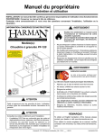
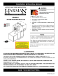
Owner’s Manual Care and Operation INSTALLER: Leave this manual with party responsible for use and operation. Owner: Retain this manual for future reference. Call your dealer for questions on Installation, Operation, or Service. NOTICE: SAVE THESE INSTRUCTIONS Model(s): PF-120 Pellet Furnace ! WARNING Please read this entire manual before installation and use of this pellet fuelburning room heater. Failure to follow these instructions could result in property damage, bodily injury or even death. • Do not store or use gasoline or other flammable vapors and liquids in the vicinity of this or any other appliance. • Do not overfire - If any external part starts to glow, you are overfiring. Reduce feed rate. Overfiring will void your warranty. • Comply with all minimum clearances to combustibles as specified. Failure to comply may cause house fire. ! WARNING HOT SURFACES! Glass and other surfaces are hot during operation and cool down. Hot glass will cause burns. • Do not touch glass until it is cooled • NEVER allow children to touch glass • Keep children away • CAREFULLY SUPERVISE children in same room as stove. ! CAUTION Tested and approved for wood pellets. Burning of any other type of fuel voids your warranty. ! High temperatures may ignite clothing or other flammable materials. • Keep clothing, furniture, draperies and other flammable materials away. CAUTION Check building codes prior to installation. • Installation MUST comply with local, regional, state and national codes and regulations. • Contact local building or fire officials about restrictions and installation inspection requirements in your area. 1 • Alert children and adults to hazards of high temperatures. NOTE To obtain a French translation of this manual, please contact your dealer or visit www.harmanstoves.com Pour obtenir une traduction française de ce manuel, s’il vous plaît contacter votre revendeur ou visitez www. harmanstoves.com Harman® • PF-120 Owner’s Manual_R2 • 2014 -___ • 07/14 3-90-08120c 1 Welcome Read this manual before operating this appliance. Please retain this Owner’s Manual for future reference. Read the Installation Manual before making any installation or finishing changes. A.Congratulations This owner’s manual should be retained for future reference. We suggest that you keep it with your other important documents and product manuals. Congratulations on selecting a Harman® PF-120 Pellet Furnace. The Harman® PF-120 Pellet Furnace you have selected is designed to provide the utmost in safety, reliability, and efficiency. Your new Harman® PF-120 Pellet Furnace will give you years of durable use and trouble-free enjoyment. Welcome to the Harman® family! As the owner of a new pellet furnace, you’ll want to read and carefully follow all of the instructions contained in this owner’s manual. Pay special attention to all cautions and warnings. Local Dealer Information Dealer: Fill in your name, address, phone and email information here and appliance information below. Dealer Name: ________________________________________________________ Address: ____________________________________________________________ ____________________________________________________________ Phone: _____________________________________________________________ Email: _____________________________________________________________ Appliance Information: Brand:_ ________________________________________________ Model Name:_ ___________________________ Serial Number:___________________________________________ Date Installed:_ __________________________ Harman PF120 Pellet Furnace Label measures: 10" high X 6.5"wide Listing Label Information/Location The model information regarding your specific furnace can be found on the rating plate usually located in the area below the hopper. PF-120 LISTED PELLET FUEL CENTRAL OR SUPPLEMENTARY FURNACES FOR RESIDENTIAL USE APPAREIL DE ChAUFFAgE CENTRAL OU SUPPLéMENTAIRE ENREgISTRé DE gRANULéS COMbUSTIbLES POUR USAgE DANS LES RéSIDENCES OMNI-Test Laboratories, Inc. Report #/Rapport #135-S-02b-2 Certified for U.S.A. and Canada Certifié pour les états-Unis et le Canada Serial No. No de série: 008 Tested January 2013 to UL 391-2010, ASTM E 1509-04, and CSA-B366.1-11 Install and use only in accordance with the manufacturer’s installation/operting instructions. Refer to authorities having jurisdiction for proper installation. Contact local building or fire officials about restrictions and installation inspection in your area. If there are no applicable local codes, follow ANSI/NFPA 211 and CAN/CSA B365. Special precautions are required for passing the chimney through a combustible wall or ceiling. Inspect and clean exhaust venting system frequently in accordance with the manufacturer’s instructions. Use a 4” diameter type “PL” venting system. A Harman PF-120 may be connected to an existing furnace or heat pump duct system. Room Heater, Pellet Fuel-Burning Type, Also for Use in Mobile Homes For use with Pelletized wood Fuel only. Model Modèle PF-120 Fuel Combustible Pellet Granulés Chimney Connector Size Grandeur du Tuyau de Cheminée BARCODE LABEL Testé en January 2013 à UL 391-2010, ASTM E 1509-04, and CSA-B366.1-11 Installez et utilisez en accord avec les instructions d’installation et d’opération du fabricant. Référez-vous à des professionnels avec autorité dans l’installation. Contactez le bureau de la construction.ou le bureau des incendies au sujet des restrictions et de l’inspection dans votre voisinage. S’il n’y a pas de codes locaux, suivez alors ANSI/NFPA211 et CAN/CSA B365. Prenez des précautions spéciales lorsque vous faites passer une cheminée à travers un mur ou un plafond combustibles. Inspectez et nettoyez le sustème de ventilation fréquemment en accord avec les instructions du fabricant. Utilisez un système de ventilation de 4” de diamètre de type “PL”. Une Harman PF-120 peut être connecté à une fournaise ou un système de pompe de chauffage déjà existants. Appareil de chauffage aux granules, type de chauffage à combustible, également destinés aux maisons mobiles FonCtionne eXClusiVeMent AVeC des GrAnules de Bois. BTUH/Kw Input Pellet Rendement des Granulés BTUH/Kw 4” 132,000 BTUH (39 Kw) Model Name Serial Number Electrical Rating Maximum Overcurrent Protection Classification électrique Protection Maximum du Courant 120V, 9.3A, 60 Hz 20 AMP Clearances to Combustibles/Espaces Libres aux Combustibles Combustibles to Filter Box on Appliance 1” (25 mm) Combustibles to Connector Pipe Des combustibles à la boîte de filtration de l’appareil *3” (76 mm) Combustibles to Appliance Des combustibles au tuyau connecteur 12” (305 mm) Supply Air Plenum to Ceiling Supply Air Plenum to Combustible Chase Des combustibles à l’appareil 1” (25 mm) Provision d’air plénum au plafond 1” (25 mm) Provision d’air plénum au châssis du combustible Appliance Body to Ceiling 28” (711 mm) Combustibles from Stove Front 36” (914 mm) De l’appareil au plafond Des Combustibles au devant du poêle *At 16” of pipe length distance from the flue collar while maintaining listed clearances from appliance body. Un tuyau de grandeur de distance de 16” de l’ouverture du ventilateur doit être en accord avec l’espace libre mentionné de l’appareil même. 48” 18” Floor Protection 12” 18” 12” 36” 36” 18” 18” fLOOR pROTecTOR 52” 8” 18” 8” Door opening side of the furnace 1” 1” Essential parts and subassemblies provided for field assembly are as follows / Pièces essentielles et sous-assemblée procurées pour l’assemblage sont les suivantes: Thermostat / Thermostat Burnpot Scraper / Grattoir de la chaudière de chauffage Datacom Wire / Fil Datacom 1638 CFM Blower / Ventilateur CFM 1638 Fan Control High Limit / Contrôle du ventilateur haute limite Fire Brick / Brique de feu Return Air Filter Box / Boîte de filtration pour retour d’air Ash Pan / Bassin des cendres Heat Exchanger Baffles / Déflecteurs d’échange de chaleur do not ConneCt this unit to A ChiMney Flue serVinG Another APPliAnCe wArninG! DO NOT operate with fire chamber or ash removal doors open. DO NOT store fuel or other combustible material within installation clearance area. CAution! Hot while in operation. DO NOT touch. Keep children, clothing, furniture and other combustible material out of the installation clearance area. DO NOT connect this unit to a chimney flue that serves another appliance. Flooring must be a non-combustible material covering the installation clearance area, and 18” in front of, and 8” to either side of the fuel loading doors. In the event of loss of electrical power: Consult owner’s manual for restarting your furnace after power is restored. U.S. ENVIRONMENTAL PROTECTION AGENCY This model is exempt from EPA certification under 40 CFR 60.531 by definition [Wood Heater (A) “air-to-fuel ratio”]. Made in the U.S.A. / Fait aux états-Unis Do Not Remove or Cover This Label/Ne pas enlever ou recouvrir cet étiquette ne PAs ConneCter Cet APPAreil à un tuyAu de CheMinée serVAnt un Autre APPAreil Attention! Ne pas opérer si la porte du combustible ou la porte de la cuvette des cendres sont ouvertes. Ne pas placer le combustible et les matières combustibles à l’intérieur de l’espace désignée pour l’installation. Attention! Chaud lors de l’opération. NE PAS toucher. Gardez les enfants, les vêtements, les meubles et les matériaux combustibles loin de l’espace désignée pour l’installation. NE PAS connecter cet apareil à un tuyau de checminée servant un autre appareil. Le plancher de l’espace désigné pour l’installation doit ê fait de matière noncombustible, de 18” en avant, et de 8” de chaque côté des portes d’entrée du combustible. Dans le cas d’un manque d’électricité: Consultez le manuel du propriétaire pour remettre la fournaise en marche lorsque l’electricité ést revenue. Manufactured by/Fabriqué par: hearth & home Technologies, Inc. 352 Mountain house Road - halifax, PA 17032 date of Manufacture / date de fabrication 2014 2015 2016 JAn FeB MAr APr MAy Jun Jul AuG seP oCt noV deC P.n. 3-90-08121 2 Harman® • PF-120 Owner’s Manual_R2 • 2014 -___ • 07/14 Rev A 3-90-08120c ! Safety Alert Key: • DANGER! Indicates a hazardous situation which, if not avoided will result in death or serious injury. • WARNING! Indicates a hazardous situation which, if not avoided could result in death or serious injury. • CAUTION! Indicates a hazardous situation which, if not avoided, could result in minor or moderate injury. • NOTICE: Used to address practices not related to personal injury. Table of Contents 1 Welcome 6 Troubleshooting and Frequently Asked Questions A. Congratulations . . . . . . . . . . . . . . . . . . . . . . . . . . . . . . . . . . 2 B. Limited Lifetime Warranty. . . . . . . . . . . . . . . . . . . . . . . . . . . 4 A. Error Code Description. . . . . . . . . . . . . . . . . . . . . . . . . . . . 21 B. Frequently Asked Questions . . . . . . . . . . . . . . . . . . . . . . . 22 C. Troubleshooting. . . . . . . . . . . . . . . . . . . . . . . . . . . . . . . . . 23 2 Product Specific and Important Safety Information A. Appliance Certification. . . . . . . . . . . . . . . . . . . . . . . . . . . . . B. Glass Specifications (Ceramic) . . . . . . . . . . . . . . . . . . . . . . C. Electrical Rating. . . . . . . . . . . . . . . . . . . . . . . . . . . . . . . . . . D. BTU & Efficiency Specifications. . . . . . . . . . . . . . . . . . . . . . 5 5 5 5 3 General Information A. Appliance Safety . . . . . . . . . . . . . . . . . . . . . . . . . . . . . . . . . 6 B. Clear Space. . . . . . . . . . . . . . . . . . . . . . . . . . . . . . . . . . . . . 6 C. Control Explanation . . . . . . . . . . . . . . . . . . . . . . . . . . . . . . . 7 D. Fuel Specification. . . . . . . . . . . . . . . . . . . . . . . . . . . . . . . . . 8 E. General Operating Information. . . . . . . . . . . . . . . . . . . . . . . 9 F. Main Operating Control . . . . . . . . . . . . . . . . . . . . . . . . . . . . 9 G. Before Your First Fire. . . . . . . . . . . . . . . . . . . . . . . . . . . . . 10 H. Wall Control. . . . . . . . . . . . . . . . . . . . . . . . . . . . . . . . . . . . 10 I. Low Fuel Sensor . . . . . . . . . . . . . . . . . . . . . . . . . . . . . . . . 10 7 Reference Materials A. Safety Reminders. . . . . . . . . . . . . . . . . . . . . . . . . . . . . . . . 24 B. Motor and Component Location. . . . . . . . . . . . . . . . . . . . . 25 C. Loss of Power Addendum . . . . . . . . . . . . . . . . . . . . . . 26-27 D. Service Parts . . . . . . . . . . . . . . . . . . . . . . . . . . . . . . . . 28-31 E. Contact Information . . . . . . . . . . . . . . . . . . . . . . . . . . . . . . 33 F. Quick Reference. . . . . . . . . . . . . . . . . . . . . . Back Page (34) = Contains updated information 4 Operating Instructions A. Starting Your First Fire. . . . . . . . . . . . . . . . . . . . . . . . . . . . B. Fire Characteristics . . . . . . . . . . . . . . . . . . . . . . . . . . . . . . C. Feed Rate Adjustment Instructions . . . . . . . . . . . . . . . . . . D. Ignition Cycles . . . . . . . . . . . . . . . . . . . . . . . . . . . . . . . . . . E. Automatic Ignition. . . . . . . . . . . . . . . . . . . . . . . . . . . . . . . . F. Manual Ignition. . . . . . . . . . . . . . . . . . . . . . . . . . . . . . . . . . 11 11 11 12 13 14 5 Maintenance and Service A. Proper Shutdown Procedure . . . . . . . . . . . . . . . . . . . . . . . 15 B. Quick Reference Maintenance Chart. . . . . . . . . . . . . . . . . 15 C. General Maintenance. . . . . . . . . . . . . . . . . . . . . . . . . . . . . 15 D. Ash Removal . . . . . . . . . . . . . . . . . . . . . . . . . . . . . . . . . . . 16 E. Burnpot Maintenance. . . . . . . . . . . . . . . . . . . . . . . . . . . . . 17 F. Accordion Heat Exchanger. . . . . . . . . . . . . . . . . . . . . . . . 18 G. Combustion Blower Chamber . . . . . . . . . . . . . . . . . . . . . . 19 H. Distribution Blower & Air Filter. . . . . . . . . . . . . . . . . . . 19-20 I. Tube Heat Exchanger . . . . . . . . . . . . . . . . . . . . . . . . . . . . 20 3 Harman® • PF-120 Owner’s Manual_R2 • 2014 -___ • 07/14 3-90-08120c B. Limited Lifetime Warranty HARMAN® CENTRAL HEATING PRODUCTS LIMITED wARRANTY Hearth&HomeTechnologiesInc.,onbehalfofitsHarman®brand(”HHT”),extendsthefollowingwarrantyforallHarman® furnaceandboilerproducts(“Products”)thatarepurchasedfromanHHTauthorizeddealer. warranty Coverage:Subjecttotheconditions,exclusionsandlimitationssetforthbelow,HHTwarrantstotheoriginal owneroftheProducts,andtoanytransfereetakingownershipoftheProductsatthesiteoforiginalinstallationwithintwo yearsfollowingthedateoforiginalpurchase,thattheProductswilloperatefreefromdefectsinmaterialandworkmanship undernormalconditionsanduse,asdescribedintheoperatinginstructionsfurnishedwiththeProduct,duringthewarranty perioddescribedbelow.HHTwill,atitsoption,repairorreplaceanyProductcoveredbythiswarrantythatisdeterminedto bedefectiveinmaterialorworkmanship. warranty Period:Thewarrantyperiodrunsforsixyears,exceptformechanicalandelectricalcomponents,whichare warrantedforthreeyears.Thewarrantyperiodbeginsontheearlierof:(i)thedateofinvoicefortheProduct;(ii)inthecase ofnewhomeconstruction,thedateoffirstoccupancyoftheresidenceorsixmonthsafterthedateofsaleoftheProduct byanHHTauthorizeddealer,whicheveroccursfirst;or(iii)thedate24monthsfollowingthedateofProductshipmentfrom HHT,regardlessoftheinvoiceoroccupancydate. warranty Conditions:ThiswarrantyappliesonlytoProducts:(i)installed,operated,andmaintainedasrecommended intheProductuser’smanual;(ii)purchasedthroughanHHTauthorizeddealer;(iii)whileremainingatthesiteoforiginal installation;and(iv)thathavenotbeenalteredafterleavingthefactory. How to File a Claim:ClaimsmustbemadewithinthewarrantyperiodtothedealerwhosoldtheProduct.Ifthatdealer cannotprovidethewarrantyservice,contactthenearestHHTauthorizeddealer.Additionalservicefeesmayapplyifyou areseekingwarrantyservicefromadealerotherthanthedealerfromwhomyouoriginallypurchasedtheProduct.Travel andshippingchargesforpartsarenotcoveredbythiswarranty. warranty Exclusions: This warranty does not cover the following: (1) consumable and normal wear items, including, withoutlimitation,flameguides,grates,coalbars,afterburnerhoods,firebrick,gaskets,paint,glassdiscoloration,burnpot housing weldments, burnpot grate weldments (pellet or corn), burnpot front plates (pellet or corn), burnpot front plate locks,cornaugerextensions,ceramicinserts,andceramicinsertplates;(2)noisecausedbyminorexpansion,contraction or movement of parts; (3) damage resulting from: (i) failure to install, operate or maintain the Product according to the installationandoperatinginstructionsandlistingagentidentificationlabelfurnishedwiththeProduct;(ii)failuretoinstall theProductaccordingtolocalbuildingcodes;(iii)shippingorimproperhandling;(iv)abuse,misuse,continuedoperation with damaged, corroded or failed components, accident, or incorrectly performed repairs; (v) environmental conditions, inadequateventilation,negativepressureordraftingcausedbytightlysealedconstruction,insufficientmake-upairsupply, orhandlingdevicessuchasexhaustfansorforcedairfurnacesorothersuchcauses;(vi)useoffuelsotherthanthose specifiedintheoperatinginstructions;(vii)installationoruseofcomponentsoraccessoriesnotsuppliedwiththeProduct or authorized and approved in writing by HHT; (viii) modification of the product not expressly authorized and approved byHHTinwriting;or(ix)interruptionsorfluctuationsofelectricalpowersupplytotheProduct;(4)non-HHTcomponents oraccessoriesusedinconjunctionwiththeProduct;(5)theProducts’capabilitytoheatadesiredspace;informationis providedtoassisttheconsumerandthedealerinselectingtheproperProductfortheapplication;considerationmustbe giventoProductlocationandconfiguration,environmentalconditions,insulationandairtightnessofthestructure;or(6) additionalorunusualutilitybillsincurredduetoanymalfunctionordefectinProducts. Limitations of Liability: Repair or replacement in accordance with the provisions of this warranty will be the owner’s exclusiveremedyforandwillconstituteHHT’ssoleobligationunderthiswarranty,underanyotherwarranty(expressor implied),orincontract,tortorotherwise.Noemployee,agent,dealer,orotherpersonisauthorizedtogiveanywarrantyon behalfofHHT.TOTHEEXTENTALLOWEDBYLAW,HHTMAKESNOOTHERWARRANTY,EXPRESSORIMPLIED, INCLUDINGANYWARRANTYOFMERCHANTABILITYORFITNESSFORAPARTICULARPURPOSE.HHTWILLNOT BELIABLEFORANYCONSEQUENTIALORINCIDENTALDAMAGESARISINGOUTOFDEFECTSINORUSEOFTHE PRODUCTS.Somestatesdonotallowexclusionsorlimitationofincidentalorconsequentialdamages,sotheselimitations maynotapplytoyou.Thiswarrantygivesyouspecificrights;youalsomayhaveotherrights,whichvaryfromstatetostate. Thedurationofanyimpliedwarrantyislimitedtothedurationofthewarrantyperiodspecifiedherein. L:\DOCS\JED\HHT\Warranties\HarmanCentralHeatingProductsWarranty6.16.09CLN 4 Harman® • PF-120 Owner’s Manual_R2 • 2014 -___ • 07/14 3-90-08120c 2 Product Specific and Important Safety Information A. Appliance Certification D. BTU & Efficiency Specifications MODEL: Pellet Furnace - PF-120 LABORATORY: OMNI Test Laboratories, Inc Particulate Emissions Rating: N/A REPORT NO. 135-S-02b-2 *BTU Output: 8,000 - 120,000 / hr TYPE: Pellet Fueled Central/Supplementary Heating Capacity: N/A STANDARD(s): UL 391-2010, ASTM E 1509-04, and CSA-B366.1-11 Hopper Capacity: 160 lbs Fuel: Wood Pellets Shipping Weight: 580 lbs NOTE: This installation must conform with local codes. In the absence of local codes you must comply with the UL 391-2010, ASTM E 1509-04, and CSA-B366.1-11 & (UM) 84-HUD The PF-120 Pellet Furnace by Harman® is exempt from Environmental Protection Agency certification under 40 CFR 60.531 y definition [Wood Heater (A) “Air to Fuel Ratio]. *BTU output will vary, depending on the brand of fuel you use in your appliance. Consult your dealer for best results. WARNING! Risk of Fire! Hearth & Home Technologies disclaims any responsibility for, and the warranty and agency listing will be voided by the below actions. DO NOT: Note: This appliance is also approved for installation into a shop. • Install or operate damaged appliance B. Glass Specifications • Install other than as instructed by Hearth & Home Technologies • Modify appliance This appliance is equipped with 5mm ceramic glass. Replace glass only with 5mm ceramic glass. Please contact your dealer for replacement glass. • Operate the appliance without fully assembling all components C. Electrical Rating • Overfire 120 VAC, 60 Hz, Start 9.2 Max Amps, 7.5 Amps normal operation. NOTE: Some generator or battery back-up systems may not be compatible with the micro-processor electronics on this appliance. Please consult the power supply manufacturer for compatible systems. • Install any component not approved by Hearth & Home Technologies • Install parts or components not Listed or approved. • Disable safety switches Improper installation, adjustment, alteration, service or maintenance can cause injury or property damage. For assistance or additional information, consult a qualified installer, service agency or your dealer. NOTE: Hearth & Home Technologies, manufacturer of this appliance, reserves the right to alter its products, their specifications and/or price without notice. Harman® is a registered trademark of Hearth & Home Technologies. 5 Harman® • PF-120 Owner’s Manual_R2 • 2014 -___ • 07/14 3-90-08120c 3 General Information A. Appliance Safety B.Clear Space WARNING! DO NOT operate furnace before reading and understanding operating instructions. Failure to operate furnace according to operating instructions could cause fire or injury. Warning! RISK OF FIRE! Do NOT place combustible objects in front or to the sides of the appliance. High temperatures may ignite clothing, furniture or draperies. ! WARNING HOT SURFACES! Glass and other surfaces are hot during operation AND cool down. Hot glass will cause burns. • DO NOT touch glass until it is cooled • NEVER allow children to touch glass • Keep children away • CAREFULLY SUPERVISE children in same room as furnace. • Do not touch during operation. High temperatures may ignite clothing or other flammable materials. • Keep clothing, furniture, draperies and other flammable materials away. NOTICE: Clearances may only be reduced by means approved by the regulatory authority having jurisdiction. WARNING! RISK OF FIRE! Keep combustible materials, gasoline and other flammable vapors and liquids clear of appliance. • Do NOT store flammable materials in the appliance’s vicinity. • Do NOT use gasoline, lantern fuel, kerosene, charcoal lighter fluid or similar liquids to start or “freshen up” a fire in this heater. Keep all such liquids well away from the heater while it is in use as combustible materials may ignite. Contact your dealer or Hearth & Home Technologies if the barrier is not present or help is needed to properly install one. If you expect that small children or vulnerable adults may come into contact with this appliance, the following precautions are recommended: • Install a physical barrier such as: - A decorative fire screen. - Adjustable safety gate. • Install a switch lock or a wall/remote control with child protection lockout feature. • Never leave children alone near a hot furnace, whether operating or cooling down. • Teach children to NEVER touch the furnace. • Consider not using the furnace when children will be present. Contact your dealer for more information, or visit: www. hpba.org/safety-information. To prevent unintended operation when not using your furnace for an extended period of time (summer months, vacations, trips, etc): • Unplug furnace from receptacle. 6 Harman® • PF-120 Owner’s Manual_R2 • 2014 -___ • 07/14 3-90-08120c C. Control Explanation Power Light Indicates power to the control, and is also used during “Test” to check the Low Fuel Sensor operation. LED will blink to indicate battery back-up shutdown if applicable. Feed adjuster Sets the maximum feed rate Test Runs all motors at full speed for one minute to check operation. After one minute the combustion blower will go to it’s minimum speed and remain there. This is to allow for low draft voltage adjustment. Status Light Will be lit in either automatic or service mode when pointer is not within off position band except after normal shut down. Lighting Mode Selector Switched between Auto and Manual lighting Low Fuel Light Indicates that fuel in the hopper is low and needs to be refilled. Low Fuel LED stays on for 15 seconds after new fuel covers sensor. Combustion Blower Light Indicates Power to combustion blower Mode Selector See explanation below. Feed Motor Light Indicates Power to the feed motor. Igniter Light Indicates power to the igniter 7 Diagnostic Display Port Requires special DDM monitor supplied exclusively to service technicians. Temp dial The “Temp Dial” should be in the “Normal Setting” position except when service work is being done. It also allows you to adjust the fire temperature when the “Mode Selector” is in “ Service Mode” using the scale marked from 1 to 7. Note: Due to variations in the electronics of the control board and wall control this is an approximate temperature and may vary +/- 2° Harman® • PF-120 Owner’s Manual_R2 • 2014 -___ • 07/14 3-90-08120c D. Fuel Specifications Fuel and Fuel Storage Pellet fuel quality can fluctuate from manufacturer to manufacturer, and even from bag to bag. Hearth & Home Technologies recommends using only fuel that is certified by the Pellet Fuels Institute (PFI). Fuel Material • Made from sawdust and/or other wood by-products • Source material typically determines ash content Higher Ash Content Material • Hardwoods with high mineral content • Bark and leaves as source material • “Standard” grade pellets and other bio-mass Lower Ash Content Material • Softwood; pine, fir, etc. • Materials with lower mineral content • “Premium” grade pellets CAUTION! Do not burn fuel that contains an additive; (such as soybean oil) • May cause hopper fire Size • Pellets are either 1/4 inch or 5/16 inch (6-8mm) in diameter • Length should be no more than 1-1/2 inches (38mm) • Pellet length can vary from lot to lot from the same manufacturer Performance • Higher ash content requires more frequent maintenance. • “Premium” grade pellets will produce the highest heat output. • Burning pellets longer than 1-1/2 inches (38mm) can cause inconsistent feeding and/or ignition. We recommend that you buy fuel in multi-ton lots whenever possible. However, we do recommend trying different brands prior to purchasing multi-ton lots, to ensure your satisfaction. CAUTION! Tested and approved for use with wood pellets ONLY. Burning of any other fuel will void your warranty. • Damage to product may result Read the list of ingredients on the packaging. If you are buying wood pellets, the only ingredient listed should be wood fiber or sawdust. Clinkers Minerals and other non-combustible materials, like sand, will turn into a hard glass-like substance when heated. Trees from different areas will vary in mineral content. For this reason, some fuels will produce more clinkers than others. ! Moisture Always burn dry fuel. Burning fuel with high moisture content takes energy to dry and tends to cool the appliance thus, robbing heat from your home. Damp pellet fuel could turn back into sawdust which does not flow properly through the feed system. CAUTION Do not burn garbage, gasoline, naptha, engine oil or other inappropriate materials When changing from “Premium” grade pellets to a “Standard” or “Economy” grade fuel, the FEED ADJUSTER will likely need adjusted to a lower setting. When under maximum demand, ensure there is no unburned fuel being pushed into the ash pan. Storage • Wood pellets should be left in their original sealed bag until ready to use, to prevent moisture. • Do not store fuel within the specified clearance areas, or in a location that will interfere with routine cleaning and maintenance procedures. ! CAUTION Tested and approved for use with wood pellets ONLY. Burning of any other fuel will void your warranty. NOTICE Hearth & Home Technologies is not responsible for furnace performance or extra maintenance required as a result of using fuel with higher ash or mineral content. 8 Harman® • PF-120 Owner’s Manual_R2 • 2014 -___ • 07/14 3-90-08120c E.General Operating Information F. Main Operating Control 1. Control Calls For Heat The appliance is like most modern furnaces; when the control calls for heat, your appliance will automatically light and deliver heat. The control can be covered, or uncovered as shown in Figure 3.1. There are tabs provided on the cover for each position. Simply move the cover to the desired position by placing the tabs of the cover in the proper slots. When the room is up to temperature and the control is satisfied, the appliance will shut down. 2. Fan Limit Control This appliance is equipped with a Fan Limit Control switch that operates the fan as the plenum temperature rises and falls. The control works independent from the control board. ! WARNING Do not store fuel or other combustible material within the marked installation clearances. Do not operate with fuel-loading or ashremoval doors open. ! CAUTION Hot while in operation. Do not touch during operation. Keep children, clothing, furniture, and other combustible material out of the installation clearance area. ! WARNING Fire Hazard. Keep combustible materials, gasoline and other flammable vapors and liquids clear of appliance. • DO NOT store flammable materials in the appliance’s vicinity. • NEVER use gasoline, GASOLINE-TYPE lantern fuel, kerosene, charcoal lighter fluid, or similar liquids to start or “freshen up” a fire in this heater. Keep all such liquids well away from the heater while it is in use. • DO NOT BURN GARBAGE, GASOLINE, drain oil OR OTHER flammable MATERIALS. • DO NOT USE CHEMICALS Or FLUIDS TO START THE FIRE. • Combustible materials may ignite. • Inspect and clean flues and chimney regularly Figure 3.1 9 Harman® • PF-120 Owner’s Manual_R2 • 2014 -___ • 07/14 3-90-08120c G. Before Your First Fire 1. Make sure your appliance has been properly installed and that all safety requirements have been met. Pay particular attention to the fire protection and venting instructions. 2. Double check that the ash pan and firebox are empty! 3. Close the front door. ! CAUTION Do not burn garbage, gasoline, naptha, engine oil or other inappropriate materials I. Low Fuel Sensor H.Wall Control The wall control acts like a thermostat, a thermister in the wall control is sending temperature information back to the micro processor on the furnace. This information is used to determine the need to increase or decrease the size of the fire according to the temperature demand. There is a low fuel sensor in the hopper that tells the control that the fuel level in the hopper has dropped below the sensor. When this happens, the Low Fuel light on the Wall Control will start to blink. You then know that it is time to fill the hopper with pellets. Setting The Room Temperature To set the room temperature, simply turn the temperature dial to the desired setting. The control and the furnace will then perform to achieve the set temperature. Note: Testing the low fuel sensor can be done by turning the FEED ADJUSTER knob to “Test”. The POWER light will go off when the sensor is uncovered and will light when the sensor is covered again. Note: The minimum temperature you can set with a full counter-clockwise knob position is 58 degrees. The maximum temperature you can set with a full clockwise knob position is 90 degrees. Note: The LOW FUEL light on the Furnace Control will light at the same time. Only the LOW FUEL light on the Furnace Control will remain lit for three minutes after the sensor is covered with pellets. See Note below. Wall Control calibration: The “Normal Setting” on the Temp Dial of the Furnace Control (See Fig.44) calibrates the Wall Control temperature span. If the Temp Dial is not pointing to the “Normal Setting”, the temperature span could vary by 3 degrees up or down depending on the Temp Dial knob setting. Note: The Low Fuel light indicates that there is power going to the auxiliary leads in the circuit breaker junction box. (120 VAC 60 Hz Max. 1 Amp.)The auxiliary power leads could be used if a bulk hopper and auger system were installed. (see wiring diagram on page 36) Type of Fuel Pelletized wood only. Note: The lower the ash content of the pellets means less heat exchanger surface cleaning that will be needed. The cleaner these surfaces are kept, the more efficient the furnace will be. 10 Harman® • PF-120 Owner’s Manual_R2 • 2014 -___ • 07/14 3-90-08120c 4 Operating Instructions A.Starting Your First Fire B.Fire Characteristics 1. The wall control is required for proper operation of this appliance in “Automatic” mode. At this time, fill the hopper with pellets, insure the control is set to “OFF”. Figure 4.1. Plug the power cord into a properly grounded, nearby outlet. A properly adjusted fire has a medium active flame pattern that extends out of the burn pot approximately 6 inches (152mm). 2. Once power is present, the unit it will run through a quick diagnostics test to insure the control is operating properly. This is normal. 3. For your first fire it may be necessary to purge the auger system by putting the feed adjuster knob to “Test” prior to starting the unit. Figure 4.2. This insures that plenty of fuel enters the burn pot for proper ignition. ! CAUTION Do not use chemicals or fluids to start fire 4. Flip toggle switch to desired mode “auto or manual”. Figure 4.3. Set feed adjuster knob to desired setting and turn mode dial to “Automatic” or “Service” Figure 4.4. Note: Feed rate of #4 is a good starting point. Adjustments made need to be made depending on fuel quality and/or heat output desired. 5. The fuel feed system and the igniter should now be on (If unit is set to auto mode). 6. Once the appliance has ignited, let it burn for approximately 7-10 minutes. After this time, the igniter light should turn off and the unit should begin to operate per the settings at the control. C.Feed Rate Adjustment Instructions The feed adjustment control is factory set at #4, and should be adequate for most fuels. However, if the flame height is too high or too low, you will need to adjust the feed rate. Wait until the appliance has been burning for 15 minutes before making your adjustments and allow 15 minutes for feed adjustment to take effect. ! CAUTION Odors and vapors released during initial operation. • Curing of high temperature paint. • Open windows for air circulation. Odors may be irritating to sensitive individuals. ! CAUTION DO NOT BURN GARBAGE, GASOLINE, DRAIN OIL, OR OTHER FLAMMABLE LIQUIDS. ! CAUTION Hot while in operation. Do not touch. Keep children, clothing, furniture, and other combustible material out of the installation clearance area. ! WARNING Do not operate with hopper or ash removal doors open. Figure 4.1 Figure 4.2 ! WARNING Do not store fuel or other combustible material within installation clearance area. FOR SAFETY KEEP FIRING AND ASH PIT DOORS TIGHTLY CLOSED. OPERATE THE ELECTRIC FURNACE PERIODICALLY TO ENSURE THAT IT WILL OPERATE SATISFACTORILY WHEN NEEDED. Figure 4.3 11 Figure 4.4 Harman® • PF-120 Owner’s Manual_R2 • 2014 -___ • 07/14 3-90-08120c D.Ignition Cycles 1. At the beginning of each ignition cycle, it is normal to see some smoke in the firebox. The smoke will stop once the fire starts. 2. The distribution blower will automatically turn on after your fan limit control has reached the set temperature. This blower transfers heat from your appliance through your duct. In “Automatic” mode however, the blower will turn on and off in accordance to what temperature the fan limit control is reading in the plenum. When the wall control is satisfied the blower will shut down until the wall control sees a demand for heat. 3. Occasionally the appliance may run out of fuel and shut itself down. When this happens, the unit will need to be turned to the off position and restarted. ! WARNING Fire Risk Do NOT operate appliance: • With fuel-loading or ash-removal doors open. • Burnpot floor open. • Cleaning slide plates open. Do NOT store fuel: • Closer than required clearances to combustibles to appliance • Within space required for loading or ash removal. If needed, follow the instructions in Section A, “Starting Your First Fire”. 12 Harman® • PF-120 Owner’s Manual_R2 • 2014 -___ • 07/14 3-90-08120c E.Automatic Ignition 1. If starting after an empty hopper, turn Feed Adjuster to “TEST” (for one 60 second cycle). This will charge pellets into the auger tube and also allow you to check the motors for operation. Figure 4.5. NOTE: The auger motor will not operate with the furnace door open. 2. Turn Feed Adjuster to #4. Figure 4.5 If this is your first fire, or you are trying different pellets, set the feed adjuster to #4, Figure 4.6. This is a conservative number and will probably need to be increased if maximum BTU output is desired. After you know a feed rate setting that works well for your application, use that setting. 3. Flip the Igniter Switch up into the “AUTO-LIGHT” position, Figure 4.7. ! Figure 4.6 Fire Risk Do NOT operate appliance: • With fuel-loading or ash-removal doors open. • Burnpot floor open. • Cleaning slide plates open. Do NOT store fuel: • Closer than required clearances to combustibles to appliance • Within space required for loading or ash removal. ! Figure 4.7 13 WARNING WARNING HOT WHILE IN OPERATION. KEEP CHILDREN, CLOTHING, AND FURNITURE AWAY. CONTACT MAY CAUSE SKIN BURNS. Harman® • PF-120 Owner’s Manual_R2 • 2014 -___ • 07/14 3-90-08120c F. Manual Ignition Lighting the fire manually will not be necessary unless the igniter system fails. 1. Flip the Igniter Switch Down into the “MANUAL-LIGHT” position. See Figure 4.8. 2. Open inner and outer ash doors as shown in Figures 5.1 thru 5.3. Located in the maintenance and service sections of this manual. 3. Fill burnpot with pellets as shown in Figure 4.9. Only fill level with the front edge. ( DO NOT OVERFILL ) 4. Have matches or other ignition source ready. This will start the combustion blower and allow the ESP to control the fire in relation to the Temp Dial setting 1 through 7. Once the fire is well established the Temp Dial can remain on any number setting desired, or changed to the “AUTOMATIC” setting. If you change to “AUTOMATIC” remember to set the Temp Dial to desired temperature. NOTE: When the Switch is set to Manual-Light in the “AUTOMATIC” mode, the wall control will function as in Auto-Light except the fire will not be allowed to go out. It will only be allowed to go to a minimum burn rate between the times the wall control is calling for heat. This rate is about 1 pound of fuel per hour. ! 5. Turn Mode Selector to “SERVICE” Figure 4.10. WARNING NEVER USE GASOLINE, GASOLINE-TYPE LANTERN FUEL, KEROSENE, CHARCOAL LIGHTER FLUID, OR SIMILAR LIQUIDS TO START OR “FRESHEN UP” A FIRE IN THIS FURNACE. KEEP ALL SUCH LIQUIDS WELL AWAY FROM THE FURNACE WHILE IN USE 6. Apply starting gel as shown in Figure 4.11. Figure 4.8 NOTE: Stirring the starting gel into the pellets usually allows the fire to become established quicker. ! CAUTION • A vapor flash could occur if too much time is allowed to pass before lighting the starting gel. • Care must be taken not to get starting gel on your hands or clothing. Serious burns could occur during the lighting process. • Never try to apply more starting gel to an already burning fire, or a fire with smoldering pellets. 7. Light the starting gel with a match. Figure 4.9 8. Close the doors The fire will light and the control will adjust the fire to the proper level according to the temperature reading at the wall control. RT GE ER L STA Figure 4.10 Figure 4.11 14 Harman® • PF-120 Owner’s Manual_R2 • 2014 -___ • 07/14 3-90-08120c 5 Maintenance & Service When properly maintained, your furnace will give you many years of trouble-free service. Contact your dealer to answer questions regarding proper operation, trouble-shooting and service for your appliance. Visit www.harmanstoves.com to find a dealer. We recommend annual service by a qualified service technician. A. Proper Shutdown Procedure ! B. General Maintenance Types of Fuel The type of fuel you are burning will dictate how often you have to clean your burnpot. If the fuel you are burning has a high dirt or ash content, it may be necessary to clean the burnpot more than once a day. Dirty fuel will cause clinkers to form in the burnpot. A clinker is formed when dirt, ash or a non-burnable substance is heated to 2000°F (1093°C) and becomes glass-like. CAUTION Shock and Smoke Hazard • Turn unit to the off position, let appliance completely cool and combustion blower must be off. Now you can unplug appliance before servicing. • Smoke spillage into room can occur if appliance is not cool before unplugging. • Risk of shock if appliance not unplugged before servicing appliance. Follow the detailed instructions found in this section for each step listed in the chart below. Cleaning Cycle Meter A cleaning cycle hour meter (pictured below) keeps track of the total accumulated hours the feeder motor runs, not the number of hours the unit is in operation. By knowing this you can keep track of how often you need to clean the burnpot and heat exchanger with your brand of pellets. Some recommended hourly intervals are: 50 hours for the burnpot. 100 hours for a complete cleaning. After cleaning is completed, reset the hour meter by pushing the reset switch located in the upper left hand corner of the control. C. Quick Reference Maintenance Chart Frequency Cleaning or Inspection Daily Weekly Monthly Ash Pan / Ash Removal from Firebox 100-120 hours OR X Heat Exchanger 100-120 hours OR X Blower, Combustion (Exhaust) More frequently depending on the fuel type OR X OR X Blower, Distribution Door Gasket Inspection Prior to heating season OR Exhaust Path More frequently depending on ash build-up OR Firebox - Prepare for Non-Burn Season At end of heating season OR Burnpot - Burning pellets - hardwood 50 Hours OR X Burnpot - Burning pellets - softwood 60 Hours OR X Glass When clear view of burnpot becomes obscure OR Hopper / Hopper Lid Gasket Venting System More frequently depending on the fuel type Yearly X X X X OR X OR X NOTICE: These are recommendations. Clean more frequently if you encounter heavy build-up of ash at the recommended interval or you see soot coming from the vent. Not properly cleaning your appliance on a regular basis will void your warranty. 15 Harman® • PF-120 Owner’s Manual_R2 • 2014 -___ • 07/14 3-90-08120c D. Ash Removal It is recommended to remove the ashes when the furnace is not in operation. This lessens the chances of coming in contact with hot surfaces. Ashes can be removed while in operation but, extra care must be taken. Open Outer Ash Door Lift the two latches shown in Figure 5.1 and open the outer door as shown in Figure 5.2. If the Distribution Blower is running when the outer door is open, some air will escape around the door opening. This is not a problem, however any dust that is caused in the ash removal process can potentially be blown around. Outer Door Latches Open Inner Ash Door Lift latches shown in Figure 5.2 and open the inner door as shown in Figure 5.3. NOTE: Keep hopper lid and inner door closed during operation and maintain all seals in good condition. Figure 5.1 Remove Ash Pan Always wear gloves to remove ash pan. Grab the ash pan by the handle and pull it out of the furnace. Lift the handle and use it for carrying the ash pan. Close the inner door before disposing of the ashes. Disposal of Ashes Ashes should be placed in a metal container with a tight fitting lid. The closed container of ashes should be placed on a non-combustible floor or on the ground, well away from all combustible materials, pending final disposal. If ashes are disposed of by burial in soil or otherwise locally dispersed, they should be retained in the closed container until all cinders have thoroughly cooled. Inner Door Latches Soot and Fly-ash: Formation and Need for Removal The products of combustion will contain small particles of fly-ash. The fly-ash will collect in the exhaust venting system and restrict the flow of the flue gases. Incomplete combustion, such as, during startup, shutdown, or incorrect operation of the furnace will lead to some soot formation which will collect in the exhaust venting system. The exhaust venting system should be inspected at least twice monthly to determine if cleaning is necessary. Figure 5.2 Figure 5.3 16 Harman® • PF-120 Owner’s Manual_R2 • 2014 -___ • 07/14 3-90-08120c E. Burnpot Maintenance When cleaning the burnpot make sure all the holes are open and free from encrusted carbon around the edges. A special effort should be made to clean the bottom inside corners of the burnpot where the auger tube enters the burnpot. Carbon deposits can build up over time in this area that could cause a restriction to the flow of pellets and/or cause the pellets to push onto the burn grate area unevenly. The three vertical cuts in the burnpot surface (Figure 5.4) are there to relieve expansion stress do to the high heat the material sees. Some unevenness may occur in this area. As long as the holes are kept clean and clear of any blockage this will not effect the operation of the unit. Removing the swing out burnpot: • Make sure the unit is cooled down or cold. Vertical cuts • Remove ash pan. Figure 5.4 • Swing the latch handle up until you feel it contact the top of the swing plate. Then push upward until you see the burnpot swing out. Figure 5.5. • Lift the burnpot up off of the swing plate in the unit. • Remove the flame guide. Pull up on handle • Empty any fines that may have built up under the burn pot grate. To do this loosen the 2 thumb screws located on the front of the burnpot and remove the cover. The air chamber can be cleaned of any ash that has fallen through the holes during operation and cleaning. Figure 5.6 Before replacing the swing out burnpot: 1. Inspect the red silicone gasket on the back of the burnpot to make sure there is no damage or carbon around the edges that may cause a poor seal. Figure 5.7. Figure 5.5 Burn pot hinge/Swing plate 2. Inspect the sealing surface on the swing plate inside the unit. The surface needs to be clean and smooth. 3. Do not forget to reinstall the flame guide or the cleanout cover. 4. Make sure the burnpot is fully seated with the latch handle down as far as it can go. Figure 5.6 Thumb screws Figure 5.7 17 Red silicone gasket Harman® • PF-120 Owner’s Manual_R2 • 2014 -___ • 07/14 3-90-08120c F. Accordion Heat Exchanger This cleaning should be done monthly, or after each ton of pellets used. The frequency of this cleaning will be directly related to the quality and the quantity of the pellets being used. Keep in mind that the cleaner the heat exchanger surface is kept, the higher the heat transfer efficiency will be. Upper Baffle Due to its ease of restarting it is recommended that the furnace be OFF and COOL before cleaning. Before starting to clean the inside of the firebox area it is recommended that all of the baffling be removed. Start with the upper heat exchanger baffle. Figure 5.8. Remove the firebrick then push straight upward on the lower ash slide angle approximately 1/2”. This will release the baffle from the positioning brackets and allow it to be tilted toward the burnpot and removed from the furnace. Ash slide angle Figure 5.8 Note: Observe the positioning tabs and bracket system on the rear of the upper baffle as it is being removed for easier replacement later. Remove the lower baffle plate. This baffle is a flat plate that sits on the firebox floor. Tip the top edge toward the burnpot and lift up and out of the furnace. Note how the baffle bottom edge sits behind the ash pan guide and against the heat exchanger. Figure 5.9. Lower Baffle Plate Ash Pan Guide Figure 5.9 With all of the baffling removed, the entire firebox area and the accordion heat exchanger can be cleaned. Use the pointed end of the scraper supplied to clean the accordion heat exchanger. A small wisp brush, wire brush, or an old stiff bristled paint brush works best for cleaning the firebox walls and baffle plates. All of the fly ash removed during cleaning will fall to the bottom of the furnace where there is an unobstructed access for cleaning. Even the bottom ends of the chains can be seen and accessed easily from the door opening. Figure 5.10. ! CAUTION Cleanout of the heat exchanger, flue pipe, chimney, and combustion blower fan housing is especially important at the end of the heating season to minimize corrosion during the summer months caused by accumulated ash. Shaker Chain Ends 18 Figure 5.10 Harman® • PF-120 Owner’s Manual_R2 • 2014 -___ • 07/14 3-90-08120c G. Combustion Blower Chamber Remove the combustion blower heat shield. There are two latches that hold the shield in place. Figure 5.11. Flip the latches up and pull the shield away from the furnace. It can not be fully removed, it can only be moved down over the wire until it hangs on the junction box. The furnace MUST be OFF and COOL before you should attempt to clean the combustion blower. The wire to the combustion blower doesn’t need to be disconnected during the cleaning process. Latch Figure 5.11 Loosen the three (3) thumb screws about 4 turns each. Figure 5.12. Hold the motor head with one hand and the blower plate handle with the other hand. Pull outward on the plate handle until the complete unit comes loose. Now rotate the plate counter-clockwise about 1/8 turn. This will allow the complete assembly to be removed from the blower chamber. Clean the blower fan blades and the blower plate sealing overlap. Figure 5.13. Note: Be careful not to bend the fan blades, this will throw the fan blade out of balance or it may rub the inner chamber, which may affect the performance of the furnace. Any horizontal and vertical flue pipe directly above the unit should be cleaned at this time. Note: The horizontal flue pipe directly above the furnace is the first place fly ash will settle, due to the slowing of flue gas velocity through horizontal pipe. Cleaning of horizontal venting pipes is very important to the efficiency of this furnace. Note: Inspection, maintenance and cleaning of the convection/distribution air filter should be done regularly. Thumb Screws Sealing Overlap 19 Figure 5.12 H. Distribution Blower and Air Filter Inspect and clean (if needed) the furnace cold air return distribution blower and air filter located just below the combustion blower chamber. This area should be inspected monthly or more frequently depending on its installation location. If the Air Filter is needing replaced use a 20”x20”x1” Air Filter, Harman® part #3-40-20201-12. Figure 5.13 Harman® • PF-120 Owner’s Manual_R2 • 2014 -___ • 07/14 3-90-08120c Clean the flue outlet throat (this is the hole that goes up into the flue pipe). Figure 5.14. Note: The ESP extends into this same area. CARE MUST BE TAKEN NOT TO DAMAGE THE ESP DURING CLEANING. ESP Clean the inner chamber of the blower housing, the furnace blower plate and sealing overlap. Figure 5.14. Inspect the tops of the heat exchanger tubes where the chain shaker mechanism is located. Make sure there are no fly ash buildups that may block the easy flow of flue gases into the combustion blower inlet hole. (A flashlight may be necessary.) Sealing overlap Inspect the chain shaker mechanism for proper operation. Note: Fly ash can build up to the top edges of the heat exchanger tubes without affecting operation. The chain shaker will cause any excess to fall down into the chamber under the tubes where it can be cleaned out through the fire box. Figure 5.14. Figure 5.14 Access to flue outlet throat ! Chain Shaker Handle CAUTION Inspect flue pipes, flue pipe joints and flue pipe seals regularly to ensure that smoke and flue gases are not drawn into, and circulated by, the air-circulation system. I. Tube Heat Exchangers: The heat exchanger tubes have an external handle that operates the cleaning mechanism. Figure 5.15. This cleaning should be done at least once a week, although it can be done more frequently. The cleaner the heat exchangers are, the more efficient the furnace will be. This cleaning can be done at any time and in any mode of operation. The handle has two directions of movement, Right to Left and In and Out. All inside surfaces of these rectangular tubes can be cleaned with this range of motion. First, with the handle pushed in, turn the handle right to left, the full sweep, several strokes. Second, with the handle pointing straight down, pull out and push inward several strokes. Third, with the handle all the way out, turn the handle right to left, the full sweep, several times. End with the handle pushed inward and pointing down. The shaker handle should be pushed inward and straight down during normal operation. Figure 5.15. Figure 5.15 Note: Fly ash can build up to the top edges of the heat exchanger tubes without affecting operation. The chain shaker will cause any excess to fall down into the chamber under the tubes where it can be cleaned out through the fire box. Figure 5.16. ! Figure 5.16 20 Lower cleanout chamber CAUTION CLEANOUT OF THE HEAT EXCHANGER, FLUE PIPE, CHIMNEY, AND DRAFT INDUCER, IF USED, IS ESPECIALLY IMPORTANT AT THE END OF THE HEATING SEASON TO MINIMIZE CORROSION DURING THE SUMMER MONTHS, CAUSED BY ACCUMULATED ASH. Harman® • PF-120 Owner’s Manual_R2 • 2014 -___ • 07/14 3-90-08120c 6 Troubleshooting and Frequently Asked Questions A. Error Code Description Status light error messages: 2 Blinks: Indicates lack of draft, door/lid is open, pressure switch is open, flue blockage. 3 Blinks: Indicates that the ESP (Exhaust Sensing Probe) has gone out of range too many times. If the unit seems to be operating normally, Perform a manual reset*. If the code persists, you’ll need to call a service technician. 4 Blinks: Can occur only in the Automatic Mode and indicates the Wall Control has failed or is not installed. If a Wall control is then installed the status light will automatically reset. 5 Blinks: (In Auto Light Mode Only) Indicates that the igniter has failed to light the fire after 4 consecutive 8 minute attempts. To reset - Turn the Mode Selector to OFF and then back to Automatic. 6 Blinks : Indicates that the control has calculated poor or incomplete combustion occurring for more than 25 minutes. Mode Selector Allows you to choose between Automatic Mode, Service Mode or OFF. Automatic Mode Automatic mode switches operational control of the furnace to the wall mounted control. This is the mode to use whenever the furnace is burning in a normal heating application. Service Mode Service mode switches control of the furnace to the temp dial. The temp dial can be set from 1 to 7 to allow a steady furnace temperature at the desired level. The main purpose of this mode is to operate the furnace without having to go back to the wall mounted control. OFF Mode Turning the mode selector to OFF will shut down the furnace. A six blink status may be set if the furnace is allowed to run out of pellets. To reset, turn mode selector to “OFF” then back on to the desired mode. If the unit was not out of pellets, see Troubleshooting section for more details. * Manual reset, disconnect power at the circuit breaker for a few seconds and reconnect. If error still occurs call your Dealer. 21 Harman® • PF-120 Owner’s Manual_R2 • 2014 -___ • 07/14 3-90-08120c B. Frequently Asked Questions ISSUES SOLUTIONS 1. Metallic noise. 1. Noise is caused by metal expanding and contracting as it heats up and cools down, similar to the sound produced by a furnace or heating duct. This noise does not affect the operation or longevity of your appliance. 2. White ash buildup on glass. 2. This is normal. Clean the glass using any non-abrasive glass cleaner. 3. Glass has buildup of black soot 3. Excessive build-up of ash. See solution #4. The lower burn settings will produce more ash, the higher burn settings produce less. The more it burns on low the more frequent cleaning of the glass is required. 4. Glass has turned dirty. 4. Excessive build up of ash. The lower burn settings will produce more ash, the higher burn settings produce less. The more it burns on low the more frequent cleaning of the glass is required. 5. Fire has tall flames with black tails and is lazy. 5. The feed rate needs to be reduced or the burnpot needs cleaning. Heat exchanger or exhaust blower needs cleaning. 6. Smokey start-up or puffs of smoke from the airwash. 6. Either the burnpot is dirty or there is too much fuel at start-up and not enough air. 7. Large flame at start-up. 22 7. This is normal. Flame will settle down once the fire is established. Harman® • PF-120 Owner’s Manual_R2 • 2014 -___ • 07/14 3-90-08120c C. Troubleshooting With proper installation, operation, and maintenance your appliance will provide years of trouble-free service. If you do experience a problem, this troubleshooting guide will assist a qualified service person in the diagnosis of a problem and the corrective action to be taken. This troubleshooting guide can only be used by a qualified service technician. Furnace DOES NOT FEED 1. No fuel in hopper. 2. Firebox draft may be too low for sensing switch in feeder circuit to operate. Check for closed doors, loose or missing gasket on doors or hopper lid. 3. Feed motor will not run until the ESP control senses a certain temperature. Maybe you did not put enough fuel or starting gel in the burn pot before manually lighting the fire. 4. Restriction in the hopper or feeder. Remove all fuel and examine. Clear the obstruction. 5. Feed motor has failed. PARTIALLY BURNED PELLETS 1. Feed rate too high. 2. Poor air to fuel mixture. (Check burn pot clean-out cover and air intake). 3. Burn pot or heat exchanger tubes may need to be cleaned. 4. Combination of all the above. 5. #6 status blink: A 6 blink control board status indication is caused by poor or incomplete combustion. The circuit board has the ability to track the combustion through feed settings and ESP temperatures. When the control board has calculated poor or incomplete combustion, it will shut down the unit as a safety feature. (Poor or incomplete combustion is a contributor of creosote which may cause a chimney fire) A 2 blink status may be caused by several things: 1. Blocked or partially blocked flue. 2. Blocked or partially blocked inlet air. a. Backdraft damper on the inlet pipe may be stuck closed. b. If outside air is installed, the inlet cover may be blocked. 3. The air chamber under the burnpot may be filled with fines and small bits of ash. 4. The holes in the burnpot may be getting filled with ash or carbon buildup. 5. Combustion blower fan blades may need cleaned. 6. Fuel restrictions as noted above. SMOKE SMELL Seal the vent pipe joints and connection to furnace with silicone. The exhaust vent is the only part of the system that is under positive pressure. SMOKE IS VISIBLE COMING OUT OF VENT 1. Air-fuel ratio is too rich. a. Feed rate too high. b. Draft too low caused by a gasket leak. LOW HEAT OUTPUT 1. Feed rate too low 2. Draft too low because of gasket leak. 3. Poor quality or damp pellets 4. Combination of 1 and 2. Helpful Hints 1. Cleaning Burn Pot Whenever your furnace is not burning, take the opportunity to scrape the burn pot to remove carbon buildup. A vacuum cleaner is handy to remove the residue. Be sure the furnace is cold if you use a vacuum. Carbon buildup can be scraped loose with the fire burning using the special tool provided with your furnace. Scrape the floor and sides of the burn pot. The carbon will be pushed out by the incoming fuel. Always wear gloves to do this. 2. Removing Ashes Turn the Temp Dial to number 1 approximately 30 minutes before removing ashes. This will result in a cooler furnace and ash pan. Maximum Feed Adjuster settings are not needed in most cases. Operating in the normal range (#4) is recommended when maximum heat output is not required. The ESP probe prevents the furnace from being over-fired. Keep the furnace free of dust and dirt. Fuel The PF-120 Pellet Furnace is approved for burning any grade of pelletized bio-mass fuel. It should be noted, however, that higher ash content will require more frequent ash removal, scraping of the burn pot, and may provide less BTU's per pound. The moisture content of pellets must not exceed 8%. Higher moisture will rob BTU's and may not burn properly. Fuel should not be stored within the furnace installation clearances or within the space required for charging and ash removal. FIRE HAS GONE OUT- Check for status light. 1. No fuel in hopper. 2. Draft is too low, blocked flue. 3. Something is restricting fuel flow. 4. Hopper lid not closed properly. 5. Feed motor or combustion blower has failed. 23 Harman® • PF-120 Owner’s Manual_R2 • 2014 -___ • 07/14 3-90-08120c 7 Reference Material A. Safety Reminders When operating your Harman® PF-120 Pellet Furnace, respect basic safety standards. Read these instructions carefully before you attempt to operate the PF-120 Pellet Furnace. Failure to do so may result in damage to property or personal injury and may void the product warranty. CAUTION: This appliance must be vented to the outside. Due to high temperatures, this furnace should be placed out of traffic and away from furniture and draperies. Children and adults should be alerted to the hazards of high surface temperatures and should stay away to avoid burn to skin and/or clothing. Young children should be carefully supervised when they are in the same room as the furnace. Clothing and other flammable materials should not be placed on or near this furnace. Installation and repair of this furnace should be done by a qualified service person. The appliance should be inspected before use and at least annually by a qualified service person. More frequent cleaning will be required. It is imperative that control compartments, burners, and circulating air passageways of this furnace be kept clean. Disposal of ashes: Ashes should be placed in a steel container with a tight-fitting lid and moved outdoor immediately. The closed container of ashes should be placed on a noncombustible floor or on the ground, well away from all combustible materials, pending final disposal. If the ashes are disposed of by burial in soil or otherwise locally dispersed, they should be retained in the closed container until all cinders have thoroughly cooled. Other waste shall not be placed in this container. Soot and fly ash: Formation and need for removal. The products of combustion contain small particles of fly ash. The fly ash will collect in the exhaust venting system and will restrict the flow of the flue gases. Pellet fuels have different ash contents depending on what type of wood has been used to make the pellets. We recommend to clean the system after approximately 1 ton of pellets have been burned and judge from that how often the furnace should be cleaned, remember if you change pellets it may change how often you have to clean your furnace. When burning wood slowly, the potential exists for creosote to form. The venting system should be inspected periodically throughout the heating season to determine if a creosote buildup has occurred. If a significant layer of creosote has accumulated (3mm or more), it should be removed to reduce the risk of a chimney fire. If a fire occurs, call the fire department, shut down the furnace, and evacuate the residence. Before using the appliance, have the venting system thoroughly inspected and replace any damaged components. 24 ! WARNING ! CAUTION Mobile/manufactured home guidelines do not allow installation in a sleeping room. THE STRUCTURAL INTEGRITY OF THE MOBILE HOME FLOOR, WALL, AND CEILING/ROOF MUST BE MAINTAINED. ! CAUTION The furnace is hot while in operation. Keep children, clothing and furniture away. Contact may cause skin burns. ! WARNING Keep combustible materials such as grass, leaves, etc. At least 3 feet away from the point directly under the vent termination. ! WARNING Use of improper fuels, fire starters or altering the furnace for higher heat output may cause damage to the furnace and could result in a House fire. Use only approved fuels and operation guidelines ! CAUTION INSPECT FLUE PIPES, FLUE PIPE JOINTS, AND FLUE PIPE SEALS REGULARLY TO ENSURE THAT SMOKE AND FLUE GASES ARE NOT DRAWN INTO, AND CIRCULATED BY, THE AIR-CIRCULATION SYSTEM. Harman® • PF-120 Owner’s Manual_R2 • 2014 -___ • 07/14 3-90-08120c B. Motor and Component Location Low Draft Pressure Switch Igniter Feed Motor Circuit Breaker Box UPS Connection NOTE: UPS connection only for power failure shut down ESP Combustion Motor PF-120 Pellet Furnace Safety Devices The Control Board/ESP combination is responsible for all high limit safety control. There are 2 high limits, one normal operation high limit and one backup high limit. The control has an automatic diagnostic circuit that continuously monitors the ESP and Room Sensor for faults. If a fault should occur, the control sends a status alert and at the same time the unit goes down to minimum feed/ minimum burn as a safety condition. 25 The Low Draft Pressure Switch is a differential pressure switch that monitors the negative pressure (Draft) in the firebox. If the draft becomes too low for proper combustion, the switch opens, cutting power to the feed motor and the igniter circuits. This switch is connected into the AC (high voltage) wiring. Harman® • PF-120 Owner’s Manual_R2 • 2014 -___ • 07/14 3-90-08120c C. Loss of Power Addendum Minimizing Smoke During Loss of Power Using Battery Back-up Harman® strongly recommends installing battery back-up to minimize entry of smoke into the room in the event of power loss. Your pellet/biomass burning appliance relies on a combustion blower to remove exhaust. A power failure will cause the combustion blower to stop. This may lead to exhaust seeping into the room. Vertical rise in the venting may provide natural draft. It is, however, no guarantee against leakage. There are two Harman® approved battery back-up options for your appliance: Uninterruptible Power Supply (UPS) UPSbattery back-ups are available online or at computer and office equipment stores: • The APC (American Power Conversion) model #BX1500G and the TrippLite OMNIVS1500 are tested and approved. Other brands or models may not be compatible. When power is lost, a fully charged UPS will power a safe, combustion blower only shut-down. Your appliance will pulse the blower every few seconds to clear exhaust until the fire is out. NOTE: The UPS provides safe shut-down only. It is not intended for continued operation. Your appliance will recognize when power is restored. What happens depends on ESP temperature: • In “Automatic” setting, units will respond to the set point and ESP temperature and resume normal operation. • In “Manual” setting: • If the ESP is cool, the appliance will remain shut down. • If the fire is out and the ESP is still warm, the feeder may restart. Since the fire is out, the ESP temperature will not rise. The unit will then shut-down, and may flash a six-blink status error. (See ESP error codes) • If the fire is still burning, it will resume normal operation. Contact your dealer if you have questions about UPS compatibility with your appliance. CAUTION! Always keep appliance doors and hopper lid closed and latched during operation and during power failures to minimize risk of smoke or burn-back. CAUTION! Use only Harman® approved battery back-up devices. Other products may not operate properly, can create unsafe conditions or damage your appliance. 26 Harman® • PF-120 Owner’s Manual_R2 • 2014 -___ • 07/14 3-90-08120c WHITE BLACK L N BLACK BR YELLOW N OW GR EE RED KB DR WHITE N E E LU WHIT Harman® • PF-120 Owner’s Manual_R2 • 2014 -___ • 07/14 SPLICE WHITE BLACK BR VIOLET CUT & SPLICE BLACK RED SKY BLUE D RE GR D RE 8 5 1 2 3 6 4 7 GREEN BLACK WHITE WHITE BLACK GREEN FEMALE POWER TO THE UPS / Plug UPS into here. When current is present, will keep UPS in Ready mode. CORD CONNECTOR 16-3 AWG PVC CORD MALE POWER FROM THE UPS / This plugs into the UPS. When power fails, UPS will supply current to the relay. These cord tails can be made from an inexpensiven 16/3 extension cord. Make sure that the MALE end is long enough to reach the receptacle on the UPS. 16-3 AWG PVC CORD CORD CONNECTOR If using a standard UPS, it should be rated at 650 or higher to ensure that the combustion motor operates until the fire is out. ( approximately 20 minutes needed ) DPDT RELAY flange mtd. GRAINGER # 2XCO2 1/2" CONDUIT 3/8"FLEX CONDUIT ( UNINTERUPTED POWER SUPPLY / BATTERY BACK-UP ) CUT & SPLICE VIOLET WHITE RED Relay enclosure box GRAINGER # 1EGH7 RED DRK BLUE N OW SKY BLUE WHITE WHITE UPS BACKUP FOR COMBUSTION MOTOR WHITE 27 WHITE PELLET FURNACE Loss of Power Addendum (Cont.) EE N MAIN JUNCTION BOX 10 AMP CIRCUIT BREAKER 3-90-08120c BROWN YELLOW D. Service Parts PF120 Service Parts Pellet Furnace 1-90-08120 Beginning Manufacturing Date: Mar 2014 Ending Manufacturing Date: Active 3 2 1 4 9 5 8 7 6 IMPORTANT: THIS IS DATED INFORMATION. Parts must be ordered from a dealer or distributor.Hearth and Home Technologies does not sell directly to consumers.Provide modelnumberandserialnumberwhenrequestingservicepartsfromyourdealerordistributor. ITEM Description COMMENTS 1 HopperAssembly 1-10-73807A 2 HopperLidAssembly 1-10-73491A SpringCatch Setof2 HopperLidCatch 1-00-00927 Y 2-00-72166B Hinge,HopperLid 3-31-73325 Gasket,HopperLid 10Ft Gasket,HopperThroat 1-00-00248 Y 3-44-677185 Y 3 FanControl/Highlimit 3-20-23139 Y 4 CombustionBlower 3-21-08639 Y MountingPlate 1-10-73416 Grommets&Spacers Pkgof25 FanBlade,43/4”SinglePaddle(CombustionBlower) CombBlowerMountingScrews 5 Filterboxkit 6 BottomCover 7 AshDoor 8 TopCover 9 ShakerCover 1-00-960026 3-21-00661 Pkgof100 CombBlowerHeatShield Y 1-00-53483208 2-00-73339 1-00-73421A Front 2-00-73338-15S Rear 2-00-73340-15S 1-10-73814-15A Front 2-00-73411-15S Rear 2-00-73412-15S 2-00-73335-15S ShakerWeldment 1-10-73354 ShakerChains Setof8 1-00-003027 Gasket,Chainshaker Pkgof2 3-44-08100-2 Additionalservicepartsonfollowingpage. 28 PART NUMBER Stocked at Depot Harman® • PF-120 Owner’s Manual_R2 • 2014 -___ • 07/14 Y 7/14 3-90-08120c PF120 Service Parts Beginning Manufacturing Date: Mar 2014 Ending Manufacturing Date: Active #10 Feeder Assembly 10.1 10.15 10.11 10.14 10.13 10.2 10.12 10.10 10.3 10.9 10.4 10.5 10.7 10.8 10.6 IMPORTANT: THIS IS DATED INFORMATION. Parts must be ordered from a dealer or distributor.Hearth and Home Technologies does not sell directly to consumers.Provide Stocked at Depot modelnumberandserialnumberwhenrequestingservicepartsfromyourdealerordistributor. ITEM Description 10.1 PelletFeederGearMotor,10RPM 3-20-02524 Y 10.2 ULFeederCam 3-31-3014 Y 10.3 FeederAirCrossoverKit 1-00-67900 Y 1-00-511427 Y 10.4 PelletAirIntakeAssembly 10.5 GasketFeederAirIntake 10.6 ULFeederAirIntake 10.7 GasketUltraAirIntake 10.8 UltraFeederWeldment 10.9 ULFeederPusherArm 9MMSiliconeTube COMMENTS 5Ft PART NUMBER 1-10-06810A Pkgof6 3-44-72224-6 Y 1-10-73811W Pkgof10 3-44-677160-10 Y 1-10-73504 PillowBlock Pkgof4 1-10-677187W Y 3-31-3614087-4 Y 10.10 Gasket,ULFeederCover 1-00-677122 Y 10.11 SlidePlateAssembly 1-10-677121A Y 10.12 ULFeederAugerAssembly 3-50-00565 Y 10.13 BearingFlangew/Hardware 1-00-04035 Y 10.14 ULFeederGearMotorBracketw/Grommet 1-00-247406 Y 10.15 ULFeederCamBlock 3-00-677154 Y Additionalservicepartsonfollowingpage. 29 Harman® • PF-120 Owner’s Manual_R2 • 2014 -___ • 07/14 3-90-08120c PF120 Service Parts Beginning Manufacturing Date: Mar 2014 Ending Manufacturing Date: Active IMPORTANT: THIS IS DATED INFORMATION. Parts must be ordered from a dealer or distributor.Hearth and Home Technologies does not sell directly to consumers.Provide Stocked at Depot modelnumberandserialnumberwhenrequestingservicepartsfromyourdealerordistributor. ITEM Description COMMENTS ACdoublePoleRelay PART NUMBER 3-20-38056 AirFliters Pkgof12 3-40-20201-12 ArrowBurnPotScraper Pkgof10 2-00-773850-10 AshDoorAshSlide 2-00-73371B AshPan 1-10-73351 BlowerAirJacket 2-00-73334B BlowerBox,AccessSide 2-00-73423B BlowerBox,Cover 2-00-73429B BlowerBox,ToporBottom 2-00-73424B BrickLedge Y 1-10-73822W FireBrick12x6x1.25” Qty2req BurnPotAssemblyw/Gasket 3-40-86125 Y 1-10-73695A Y CleanOutCover 2Sets 1-00-06623 Y ThumbScrew Pkgof10 3-31-782108-10 Y 3-00-08534 Y 3-44-35263 Y 1-00-07381 Y 3-44-73954 Y FlameGuide Flameguideinsulator Gasket,BurnPot Pkgof5 SiliconeGasket Cable2Pairtwistedcat3(50’forwallcontrol) 3-20-02583 CircuitBoardw/Knobs&Shafts 1-00-05888 CircuitPlate,studdedw/label Y 1-10-09412A ControlKnob/Shaft 25Sets Fuse,6AMP Pkgof5 1-00-015605 Y 3-20-49447-5 Y Circuitbreaker10Amp(orange-on/offswitch) 3-20-334110 Y Circuitbreakerharness-tocontrolboard 3-20-83560 Conduit,3/8”Flexible 7Ft 1-00-25043 ControlCover,Painted 2-00-73362B DiagnosticDisplayModule 3-20-05401 DDMReplacementCable Y Y 1-00-05402 DifferentialPressureSwitch 3-20-6866 Y Disconnects,Male Pkgof25 1-00-00957 Y Disconnects,Female Pkgof25 1-00-00959 Y DistributionBlower 3-21-19599 DistributionBlowermountingbracket Qty2req DraftMeterAssembly 2-00-73430B 1-00-00637 DraftMeterBolt&Tube ESP(ExhaustSensingProbe) Y 1-00-04004 Redwires 3-20-00844 Y Additionalservicepartsonfollowingpage. 30 Harman® • PF-120 Owner’s Manual_R2 • 2014 -___ • 07/14 3-90-08120c PF120 Service Parts Beginning Manufacturing Date: Mar 2014 Ending Manufacturing Date: Active IMPORTANT: THIS IS DATED INFORMATION. Parts must be ordered from a dealer or distributor.Hearth and Home Technologies does not sell directly to consumers.Provide Stocked at Depot modelnumberandserialnumberwhenrequestingservicepartsfromyourdealerordistributor. ITEM Description COMMENTS 2-00-73805B FlexConnector,3/8”Straight 3-20-1000 Heatexchangerbaffle-bottom 2-00-73314 Heatexchangerbaffle-top 1-00-73418 HourMeter 3-20-04687 IgnitionAirPump(PressureIgniton) 3-20-02679 Y 2-00-853500B Y IgniterElement(PressureIgnition) 1-00-10450 Y InnerAshdoorAssembly 1-10-73321A AirPumpBracket Y Gasket,1/4”RopeBlackw/PSA(Glass) 15Ft 1-00-2312 Y Innerashdoorgasket 10Ft 1-00-00539 Y Innerashdoorglass InnerAshDoorHinge 3-40-5555 Qty2req Innerashdoorspacersetw/gasket 1-10-08735W 1-00-232074 Junctionboxharness 3-20-73561 Labels,Caution&Danger Pkgof10 Lowfuelsensor 31 PART NUMBER FeederCover,Painted 1-00-200408541 4-20-03835 Y RingTerminal Pkgof25 1-00-01003 Y SiliconeTubing,1/4” 5Ft 1-00-5113521 Y SiliconeTubing,1/8” 5Ft 1-00-5113574 Y SleeveBushing,3/8ODx5/16OAL Pkgfo5 3-50-08288-5 Y SteelBox,4x4 3-20-52171 TempSensor 3-20-72180 Y Terminalblockforpowersupply-3Position 3-20-03018 Y Thermostatextension4Pole 3-20-04946 Thermostat,WallControl 3-20-08101 TouchupPaint,PrepaintAerosol 3-42-7737 Harman® • PF-120 Owner’s Manual_R2 • 2014 -___ • 07/14 Y 3-90-08120c 32 Harman® • PF-120 Owner’s Manual_R2 • 2014 -___ • 07/14 3-90-08120c E. Contact Information Harman®, a brand of Hearth & Home Technologies 352 Mountain House Road, Halifax, PA 17032 www.harmanstoves.com Please contact your Harman® dealer with any questions or concerns. For the location of your nearest Harman® dealer, please visit www.harmanstove.com. - NOTES ________________________________________________________________________________ ________________________________________________________________________________ ________________________________________________________________________________ ________________________________________________________________________________ ________________________________________________________________________________ ________________________________________________________________________________ ________________________________________________________________________________ ________________________________________________________________________________ ________________________________________________________________________________ NOTICE DO NOT DISCARD THIS MANUAL • Important operating and maintenance instructions included. • Read, understand and follow these instructions for safe installation and operation. • Leave this manual with party responsible for use and operation. Printed in U.S.A. - Copyright 2012 33 Harman® • PF-120 Owner’s Manual_R2 • 2014 -___ • 07/14 3-90-08120c 34 Harman® • PF-120 Owner’s Manual_R2 • 2014 -___ • 07/14 3-90-08120c ** See the section on Maintenance for more details about cleaning. * See the section on Operation for information about Manual Lighting. The furnace will ignite if the temperature in the room is less than the temperature set on the Wall Control. 10. Flip the Auto-Light switch up.* 9. Turn all other Furnace Control knobs to the settings shown.* 8. Turn the Temp Dial to the desired temperature. 7. Turn Feed Adjuster back to the #4 setting. 6. Check the Combustion Blower and Feeder Motor for operation.* 5. Turn Feed Adjuster to “Test”.* 4. Fill the hopper with pellets. 3. Scrape the air holes in the burnpot.** 2. Use shaker handle to clean the heat exchanger tubes.** 1. Turn Mode Selector to OFF. Quick Reference Guide ( Auto-Light ) F. Quick Reference Guide Temp Dial Mode Selector “Test”