1
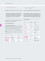
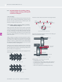
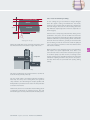
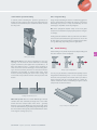
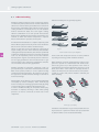
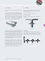
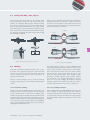
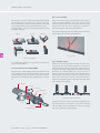
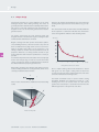
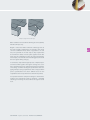
USER MANUAL
Organic coated steel
ARCELOR FCS COMMERCIAL
Arcelor Group
S T E E L
F O R
L I F E
®
USER MANUAL
Organic coated steel
1
Introduction
Advantages
3
2
Organic coated products
2.1 The Arcelor product range
2.2 The coating line
2.3 Basic characteristics of organic coated steel
5
3
General recommendations for use
9
3.1 Important notice
3.2 General recommendations
3.3 Recommendations for handling, packaging and storage
3.4 Recommendations for decoiling, slitting, cutting to length,
shearing, punching and mechanical cutting out
4
Forming of organic coated steel
4.1 Introduction
4.2 Drawing
4.3 Roll forming
4.4 Bending
4.5 Panel forming
4.6 Edge forming
4.7 Spinning
15
5
Joining organic coated steel
5.1 Adhesive bonding
5.2 Clinching
5.3 Riveting
5.4 Lockseaming
5.5 Joining with bolts, studs, clips etc
5.6 Welding
21
6
Protection and manufacturing aids
6.1 Temporary protective films
6.2 Lubricants and cleaning solvents
27
7
Design
7.1 Shape design
7.2 Joint design
7.3 Design of edges and corners
29
8
Post-treatment
35
We often wonder at the glorious
colours and intriguing surface structures of the world’s flora and fauna.
But everything in nature has a function to fulfil. Colours are there to catch
attention or warn against danger.
Surface structures capture light and
oxygen, perform a cooling function or
provide protection from the rain.
In Arcelor FCS Commercial’s organic
coated materials you will find a similar
symbiosis between function and
design. We design the surface properties and colours to meet very specific
technical and aesthetic requirements.
And at the same time, we ensure that
our products are recyclable, safe and
durable. Arcelor has opted for sustainable development, out of respect for
life. Today and tomorrow. Steel for life.
■
Today, organic coated steel offers exceptional
economic and technological advantages, which
explain its extraordinary success story in industry.
1
Introduction
Organic coated steel products are used in all sectors of industry.
In building and construction, profiles are used for wall cladding and roofing,
and also for applications such as suspended ceilings, lighting etc.
In general industry, these products have a variety of applications, including
metal furniture, HVAC (Heating, Ventilating, Air Conditioning) and many
others. And of course in the domestic appliance market, the advantages of
organic coated steel products are well known. They are successfully used for
white goods (refrigerators, washing machines etc) and small kitchen
appliances (microwave ovens etc). Brown goods (computer casings, VCR &
DVD casings etc) are another successful application.
The purpose of this document is to give you all the information you need
to take maximum advantage of everything organic coated steel has to offer.
But it is no more than a technical support tool and not intended as a
substitute for direct contact with our technical and commercial teams.
ARCELOR FCS COMMERCIAL
Arcelor Group
S T E E L
F O R
L I F E
®
1
Introduction
Advantages
economic
Coil coating lines provide high productivity and yield, reducing the cost of
applying an organic coating. Line speeds are frequently around 100 m/min.
For the user, switching from post-painting to organic coated material means
that he no longer needs to invest in his own paint shop, degreasing installations
and other surface treatment equipment, or the ensuing waste treatment.
The use of coil coated steel simplifies manufacturing operations and provides a
drastic reduction in:
• manufacturing costs
• energy costs
• manufacturing lead time
• the financial cost of managing stocks (raw materials, chemicals and
intermediate storage)
Furthermore, the use of organic coated steel significantly reduces company
taxes and insurance premiums. All taxes related to waste treatment are eliminated. In some cases, the move towards clean manufacturing can benefit from
subsidies from the state and/or the European Union.
4
ecological
Organic coated steel is certainly one of the products best able to respond to
present and future environmental regulations. Arcelor has opted for a proactive
approach to the evolution of these regulations by building respect for the environment into the life cycle of its organic coated steel products. This strategy is
pursued at all stages of the product’s life cycle:
• design: when designing new products or production processes, research
teams take their possible environmental impact into account from the
earliest stages of the project.
• production: organic coated steel is produced on industrial lines designed
to meet the most stringent environmental regulations concerning surface
treatments, solvent emissions and the absence of harmful substances in the
composition of the paint.
• transformation: using organic coated steel improves working conditions
in the workshop by eliminating the use of solvents and the handling and
storage of chemical products.
• usage: the use of organic coated steel entails no danger to the consumer
or the environment in the various sectors in which it is used, namely the
construction business, domestic appliances and industry.
• recycling: at the end of its life cycle, organic coated steel is recycled just
like any other steel product.
technological
The main advantage of organic coated steel is its consistent quality. Paint film
thickness, colour matching and surface aspect are reproducible within narrow
tolerances from batch to batch. The flexibility of the coil coating process allows
us to produce a range of different surface finishes such as smooth, orange peel,
grained, textured or embossed, which can be obtained in a wide choice of
colours (solid, metallic, pearlescent etc) and the required degree of gloss:
anything from matt to high gloss.
USER MANUAL - Organic coated steel - ARCELOR FCS COMMERCIAL
2
Organic coated products
2.1
The Arcelor product range
6
2.2
The coating line
7
2.3
Basic characteristics of organic coated steel
8
ARCELOR FCS COMMERCIAL
Arcelor Group
S T E E L
F O R
L I F E
®
2
Organic coated products
2.1
The Arcelor product range
2.1.2 Indoor building applications &
general industry
Today, Arcelor can offer a complete range of organic coated
products.
These fall into three categories:
• Conventional organic coated steels, produced in a continuous process by applying liquid paint onto a substrate.
• Laminated strip, produced on the coil coating line by
the application of a film onto a layer of adhesive
(Skinplate®).
• Colaminated strip, produced on the coil coating line by
applying a film directly onto organic coated steel.
Arcelor’s wide range of organic coated products covers all
indoor building applications and end uses in general industry.
The steel substrates used for these applications are coldrolled steel, hot-dip and electrogalvanised steel, Galfan® and
Aluzinc®. The product range for indoor building applications
and industry includes coatings with very specific properties,
such as varnishes and primers suitable for use as a base coat
and compatible with insulation foams or adhesives. Please
contact us for further information on these products and the
dimensions available.
Our range of organic coated steel products meets the
requirements of all sectors of industry.
2.1.1 Domestic appliances
6
A very wide range of high-gloss organic coated products is
available for domestic appliances.
The substrates we use for these applications are cold rolled
and galvanised steel. Different steel grades are available, for
example for bending and deep drawing applications.
The organic coated steel to be selected for these applications depends on the end use, as indicated in the table
below.
In each case there are several possibilities. Do not hesitate to
consult us to help you choose the most appropriate product
for your application.
Product
Appearance
Application
Estetic® Cold
Smooth, grained,
orange peel
Cold appliances
Estetic® Hot
Smooth, orange peel
Cooking
Estetic® Wet
Smooth, orange peel
Washing
Estetic® Bright
Smooth, orange peel
Domestic appliances
USER MANUAL - Organic coated steel - ARCELOR FCS COMMERCIAL
Product
Appearance
Applications
Polyester
Smooth,
orange peel
Air conditioners, presentation
racks, radiators, casings
Estetic® Flex
Smooth, grained
Boiler casings, rolled parts,
roller blinds, presentation racks
Estetic® Tex
Textured
Metal furniture, shelves and
shelving units, body shells for
domestic appliances
Skinplate®
Smooth, grained
Lifts, presentation racks,
doors, ceilings
Estetic® Clean
Smooth
Cold rooms
Orange peel
Cold rooms (replacing Gelcoat)
Estetic® Lighting
Smooth, grained
Lighting
Estetic® Ceiling
Matt
Metal ceilings, cappings,
internal panels
Estetic® High Tech
Textured
Consumer electronics, decoders,
hi-fi, computers, teletronics
Estetic® White board
Smooth
White boards
The coating line
2.1.3 Outdoor applications in building and
construction
2.2
For these applications, the substrate is usually galvanised
steel: Galfan® or Aluzinc®.
The choice of the paint system depends on the environmental conditions to which the product will be exposed.
A continuous coil coating line consists of three main sections: the entry section, the central or process section, and
the exit section.
In order to maintain a constant speed in the process section,
which is essential to maintaining the quality of the product,
two accumulators (looping towers) are used as buffers when
the entry or exit section of the line is stopped for joining or
cutting the strip.
Product
Thickness (microns) Appearance
Granite® HD
25
Smooth, matt, textured, grained
Granite® HDS
25 - 35
Smooth, pearly
Granite® HDX
50 - 60
Lightly grained
Granite® Farm
Front: 25
Back: 35
Smooth
Polyester
25
Smooth
PVDF
25 - 35
Smooth
2.2.2 Process section
Plastisol
100 - 200
Smooth, embossed
Skinplate®
180 - 900
Smooth, grained, various textures
Pretreatment
The surface of the strip is prepared for coating. This pretreatment is performed in various steps. First, it is degreased and
then a surface treatment coating is applied to reinforce the
adherence of the paint.
2.2.1 Entry section
Coils are placed on a pay-off reel. To allow the process to
proceed continuously, the head of the incoming coil is
stitched to the tail of the coil in process.
Arcelor’s range of organic coated steel products currently
includes over 80 options.
There is a choice of different colours, finishes (smooth,
grained, structured, orange peel, pearly, metallic, embossed,
striated etc), metallic coatings and steel grades. Each
product has its specific characteristics and applications. The
appropriate choice is therefore crucial and should be made
in close collaboration with Arcelor’s technical and sales
teams.
Coating process
The first coating head applies liquid paint to both sides of
the strip, usually primer on the topside and backcoat on the
underside. The strip is then passed through an oven, where
the solvents are extracted and the coating cured.
After leaving the oven, the strip is cooled and a topcoat is
applied to the upper surface in the second coating head,
followed by another curing and cooling cycle.
5
13
12
11
10
9
3 2
4
1
17
16
14
15
8
7
6
Legend:
1. Pay-off reel
2. Stitching machine
3. Degreasing
4. Entry looper
5. Pretreatment
6. Coater: primer coater, top & back
7. Oven*
8. Cooling
9. Coater: top
10. Coater: bottom
11. Oven*
12. Embossing roll
13. Cooling
14. Levelling (machine)
15. Exit looper
16. Inspection point
17. Coiler
* Each oven is equipped with a solvent incinerator
USER MANUAL - Organic coated steel - ARCELOR FCS COMMERCIAL
7
2
Topcoat
Primer
Surface treatment
Zinc coating
Steel
Organic coated products
The curing cycles are extremely important, since they determine the quality of the paint system in terms of hardness,
adhesion, and mechanical and chemical resistance.
2.2.3 Exit section
The strip passes through an inspection section and finally
reaches the coiler. Coil weights are adjusted to meet the customer’s requirements.
A number of different on-line quality control tests are carried out. Coil coating lines comply with quality assurance
standards such as ISO 9001, ISO 14001 and ISO TS 16949.
The dimensions tabled below give the overall dimensional
ranges. They may vary according to the combination of
product parameters specified. Please contact us for more
detailed information, especially in cases where extreme
thicknesses or widths are required.
8
Product
Thickness (mm)
Width (mm)
products
0.17 to 3
600 to 1850
Skinplate®
0.25 to 1 (1.5)
600 to 1530
0.4 to 1 (1.5)
700 to 1450
Organic coated
Colaminated
products
2.3
Basic characteristics of organic coated
steel
Organic coated steel is generally composed of a steel
substrate (cold rolled or with a zinc-based metallic
coating) with a surface treatment layer, a paint primer
coating and a topcoat. For certain applications,
a colaminated polymer film may be added, and a
temporary protective film, if required.
USER MANUAL - Organic coated steel - ARCELOR FCS COMMERCIAL
Zinc coating
Surface treatment
Backcoat
The choice of substrate has a direct influence on the
processing performance and corrosion resistance of the
organic coated product. For good corrosion resistance, a
relatively thick sacrificial zinc-based metallic coating is the
best choice. On the other hand, if the essential requirement
is an ability to sustain severe forming strains without cracking, thin and flexible crack-resistant zinc coatings are to be
preferred.
The surface treatment carried out at the beginning of the
process section prior to coating ensures good bonding
between the primer and the metal substrate.
The role of the primer is mainly to enhance the adherence of
the topcoat and improve flexibility and corrosion resistance.
The topcoat, and the colaminated film if used, provide the
required surface characteristics, such as the final appearance (colour, texture, gloss, appearance etc), hardness and
resistance to abrasion and ultraviolet radiation. Depending
on the required performance, a single (primer) or double
(primer + topcoat) paint layer can be applied on one or both
sides of the sheet.
The processing performance and other characteristics
required will vary greatly according to the type of substrate
and the paint system used. These characteristics include
paint adhesion, flexibility, hardness, resistance to surface
abrasion, corrosion resistance, appearance, gloss, foodsafe,
heat resistance, shock resistance, chemical resistance, photochemical stability (UV resistance), resistance to soiling etc.
Of course, there is no such thing as a "universal" organic
coated product that can meet all these requirements, but
we have been able to develop special products for each
type of application. It is often necessary to give priority to
one or more properties to the detriment of others. The wide
range of characteristics that can be built into organic coated
products explains the diversity of the solutions proposed by
Arcelor. It is therefore essential to draw up precise prior
specifications, so that we can define the optimum solution
in terms of technical and economic criteria.
3
General recommendations
for use
3.1
Important notice
10
3.2
General recommendations
10
3.3
Recommendations for handling,
packaging and storage
11
3.4
Recommendations for decoiling, slitting,
cutting to length, shearing, punching and
mechanical cutting out
12
ARCELOR FCS COMMERCIAL
Arcelor Group
S T E E L
F O R
L I F E
®
General recommendations for use
3.1
Important notice
The sections below define an ideal processing line for
organic coated sheets, and optimum working conditions.
They suggest a suitable solution for every type of application. However, they must not be interpreted as mandatory,
but rather as a guarantee of success.
A coil coated product and a method of processing should be
chosen by selecting a suitable substrate (cold rolled steel,
with or without a zinc-based metallic coating) which will
meet the required specifications.
3.2
10
Using an appropriate working temperature
Successful processing depends on the flexibility and hardness of the organic coating. The following graph shows how
the working temperature affects these properties.
physical properties
3
flexibility
General recommendations
The first point to be borne in mind is that the surface condition of the final component is that of the coil coated sheet
before processing. The second point is that the weakest link
in the processing chain will determine the quality of the
final product. Consequently, great care must be taken with
all processing steps in order to ensure a high-quality final
product.
For organic coated steel, a good production process is one
that keeps all the initial properties of the material intact.
Essentially, this means the avoidance of excessive deformation or damage to the surface, so as to preserve the corrosion resistance properties and attractive appearance of
the product.
hardness
Tg
temperature
Variation of coating flexibility and hardness with temperature
For the paint to be flexible and formable, organic coated
products must be processed at a temperature above the
glass transformation point (Tg). This is normally the case
when working in an ambient temperature of about 20°C. If it
is colder in the warehouse where material is stored, the coils,
sheets or blanks should be transferred to a location with a
temperature of about 20°C for 24 hours prior to processing.
This can be achieved by observing a few basic rules:
Use of dedicated processing lines and storage
facilities
If workshops and equipment are used for different products,
such as hot rolled strip, cold rolled strip, galvanised strip
with and without oiling, there is a significant risk of contamination. It is worth making an economic assessment of the
possible benefits of investing in dedicated equipment for
organic coated material, compared with what it costs to produce batches of different products on the same line, including down time for cleaning and/or changing tools before
organic coated material can be processed.
Our technical and commercial teams will be glad to help
you establish the best solution, on technical and economic
grounds.
Training personnel
Working with organic coated products requires great care
on the part of the operators. They must be made aware of
the constraints involved, and should be given specific training to this end. They should realize that they are dealing
with a high-grade product requiring special care and different working methods.
USER MANUAL - Organic coated steel - ARCELOR FCS COMMERCIAL
In extreme cases, the organic coated steel sheet can be
heated locally by installing radiant infrared heaters on the
processing line. The advantage of this procedure is that it
ensures that the organic coating has excellent formability
while retaining the same degree of hardness and chemical
resistance after cooling.
Providing inspection zones
Product inspection and monitoring should always be performed during processing, in order to detect defects such as
scratches or indentations at the earliest possible stage. The
ideal solution is to provide inspection zones with adequate
lighting. The topside of the organic coated steel (which will
be visible in the end product) must be facing upwards.
Please note that the presence of a protective film may considerably hamper inspection (see p. 28).
3.3
Recommendations for handling,
packaging and storage
3.3.1 Handling
3.3.2 Packaging
Coils, sheets, blanks and components all need to be handled
differently.
Whatever the format (coil, sheets or blanks), organic coated
products are dispatched in packaging appropriate to the
transport and handling conditions, the destination and the
intended final use. This question should be examined with
the Arcelor sales teams.
Equipment for handling coils should have a protective coating, e.g. sheathed non-metallic slings, and grips or
C-hooks with a rubber or synthetic coating. These tools must
be used with great care to avoid any hard impact which
could mark the product.
Operators should wear gloves when handling sheets manually to protect their hands from cuts. This also keeps the surface of the sheet clean.
For automatic handling, numerous solutions are available,
including robotic suction pad systems etc. An excellent system for both sheets and blanks is four-point seizure by suction pads. This system can be further improved by installing
permanent magnets at the stack edges, to maintain the
stack while the sheets are removed one by one.
Suction pad systems for handling sheets and blanks
With handling systems whereby the steel is manipulated
between tools (roller tables, stackers etc.), the tools should
make contact with the steel without slipping. Alternatively,
contact should be made with a soft surface. The use of plastic transport rollers or rubber conveyor belts are possible
solutions. The principal requirement is to ensure a soft contact surface that does not retain dust.
Manual or automatic handling operations may never
involve sliding one sheet or component over another.
Finally, when other handling systems are used, e.g. forklift
trucks, it is often sufficient to add a sheet of felt or rubber to
comply with the handling requirements for organic coated
products.
Experience has shown that it is preferable for organic coated products to be supported on their least vulnerable side
during handling, with the appearance-sensitive front side
facing upwards. This also facilitates the detection of any
surface defects.
USER MANUAL - Organic coated steel - ARCELOR FCS COMMERCIAL
The packaging of finished parts made from organic coated
steel will be the same as for post-painted components. The
parts should be placed in boxes, baskets or other containers
in such a way that they are separated from each other and
protected against damage due to friction or impact.
Corrugated cardboard spacers, foam sheets or other similar
products can be used for this purpose. Parts must never be
stacked in bulk without individual packaging.
3.3.3 Storage
The coils, sheets or blanks must be stored in clean, heated
premises, which must be at least sufficiently ventilated to
prevent moisture accumulation. If storage at a low temperature cannot be avoided, the products must be heated at
about 20°C for 24 hours prior to processing (see p. 10).
Coils should not be placed directly on the ground, but on
protective mats made of rubber, felt or similar materials,
to prevent rough surfaces or debris causing marks or indentations on the first lap of the coils. Coils and bundles of
organic coated strip must not be allowed to splay or be
stacked on top of one another. The protection should be
replaced on all partly used coils and bundles, in order to
avoid soiling and damage to the exposed laps or sheets.
It is recommended to use organic coated products within six
months of manufacture in order to conserve maximum flexibility of the organic coatings. After six months, a mechanical
densification of the structure of the organic coating may
occur, leading to loss of flexibility.
11
3
General recommendations for use
3.4
Recommendations for decoiling, slitting,
cutting to length, shearing, punching and
mechanical cutting out
3.4.1 Decoiling
The burrs are then oriented as shown in the diagram below.
The drive system for decoiling must be matched to the line
speed, in order to optimise product flow. In extreme circumstances, the drive system will also eliminate jerks, and
flapping and slipping of adjacent laps.
top side
backside
3.4.2 Slitting, cutting to length, shearing, punching
and mechanical cutting out
12
Slitting and other cutting processes for organic coated strip
are performed using the same parameters as for other products. It is essential to correctly adjust and sharpen the tools
to avoid the formation of burrs and paint slivers. Because
there is no final painting operation to cover the burrs, they
will remain visible. Paint slivers and built up edges can contaminate the tools.
burr orientation
Burr orientation after (symmetrical) slitting
The vertical and horizontal blade clearances for slitting are
defined in the following figure:
Slitting, cutting-to-length and shearing operations must be
considered at the design stage to ensure that any burrs that
may result do not affect the appearance of the finished
product or present a safety risk (cuts to the hands) during
handling etc. The following rules must be respected in order
to control the position of cutting burrs.
top shaft
blade
sheet
Ideally, the sheet should be worked from the coated side
(i.e. with the front side which will be visible in the finished
product uppermost) in order to avoid peeling of the paint in
the event of poor tool adjustment.
Symmetrical mounting of the slitting and edging wheels is
to be preferred.
top shaft
vertical clearance
(crossover)
sheet
blade
horizontal clearance
(between steel)
bottom shaft
Horizontal and vertical blade clearances in slitting
bottom shaft
Symmetrical mounting – right
top shaft
bottom shaft
Non-symmetrical mounting – wrong
USER MANUAL - Organic coated steel - ARCELOR FCS COMMERCIAL
Slitting quality is considered to be good if:
• the distorted zone is small
• the shear zone occupies about a third of the thickness
• the fracture zone is sharp, with an angle less than 5°
• there are few or no burrs
• there are no paint slivers or build up on the tools
6-8%
distorted zone (plastic rounding)
25-40%
In laser cutting, the gas used must be nitrogen. Oxygen
burns the organic coating and disturbs the laser beam,
leading to a loss of power and the appearance of burrs. The
choice of nitrogen increases the cost of cutting due to the
high flowrates required (pressure of 20 bars compared to 1
bar for oxygen).
shear zone
fracture zone
50-60%
horizontal
clearance
3.4.3 Laser and water jet cutting
little or no burr formation
α = 5°
Morphology of the cut edges
Cutting to length with a shear gives burrs oriented in opposite directions on the front and rear edges of the sheet.
blank
holder
moving blade
uncoiled strip
fixed blade
blank
Orientation of burrs in shearing
This aspect is important, since it means that it is essential to
stack the sheets perfectly vertically.
The use of disk cutters and similar techniques should be
ruled out, since they cause coating burns, and generate
chips and burrs. For roll forming for example, profilers will
find hydraulic or pneumatic shears at the line exit preferable
to circular or band saws.
Furthermore, the choice of a suitable sheet handling system
is important, particularly on punching presses. The new
mini-brush types are to be preferred to the old ball systems.
USER MANUAL - Organic coated steel - ARCELOR FCS COMMERCIAL
If the sheet has a temporary protective film, cutting can be
performed in two passes, one for the film and one for the
organic coated material. If possible, the adhesion of the film
should be sufficient to prevent peeling which could hinder
the beam. The best solution is generally to remove the film
prior to cutting, in order to conserve the excellent quality of
a laser cut (accuracy, narrowness of the heat affected zone
and absence of burrs).
Water jet cutting is very suitable for organic coated products
and requires no special adjustments. Since there is no
source of heat and no contact with a tool, this process gives
an excellent quality cut, with no burrs, no damage to the
organic coatings and no heat-affected zones. The only point
sometimes requiring attention is the presence of a protective film, which must be prevented from peeling during
cutting.
13
14
4
Forming of organic coated steel
4.1
Introduction
16
4.2
Drawing
17
4.3
Roll forming
17
4.4
Bending
18
4.5
Panel forming
19
4.6
Edge forming
20
4.7
Spinning
20
ARCELOR FCS COMMERCIAL
Arcelor Group
S T E E L
F O R
L I F E
®
4
Forming of organic coated steel
4.1
Introduction
During forming of an organic coated sheet, the appearance sensitive surface is
in direct contact with the tools. The reaction of the material to the forming loads
exerted on the surface therefore depends on the behaviour of the organic
coating, and this must be allowed for by adapting the process parameters
appropriately.
It is for this reason that it is recommended to use dedicated equipment and
workshops, with extremely clean machines and a working temperature at or
above the glass transformation point (Tg) (see p. 10).
In order to avoid scratches or even tearing of the coating in extreme cases, the
tool/sheet contact areas should be increased in order to decrease the local contact pressures and limit relative movements and friction between the tools and
the organic coated steel.
Increasing the contact area is not always easy to do directly, but can be readily
achieved indirectly by polishing the tools.
16
Relative movements depend on the forming process employed and it is often
not simple to minimize them. However, the friction coefficient can be reduced.
Polishing of the tools is again an excellent solution, and the use of appropriate
lubrication (e.g. a volatile oil) is another possibility. Organic coated sheets will
then have a very low friction coefficient, often less than 0.05 with steel tools.
In certain cases, it may be useful to protect the paint layer by adding a temporary organic film. This possibility must be examined as a function of the intended
forming process.
The strain levels arising from the design of the component and the forming
process must be compatible with the formability of the steel substrate, the
metallic coating when present, and the paint system. This aspect will be discussed in detail in the section on component design (see p. 29).
The thickness to be taken into account when designing a forming process is the
total product thickness (steel + metalllic coating + paint + protective film). It is
this value that determines tool clearances. For thin gauges or applications
requiring very precise adjustments, if the thickness of the coatings is not included in the calculation, the coating will be crushed. It is easy to make this mistake,
since the organic coated steel thicknesses set out in the standards are the thickness of the steel substrate + metallic coating, but do not include the organic
coating.
USER MANUAL - Organic coated steel - ARCELOR FCS COMMERCIAL
4.2
Drawing
punch
restraining draw bead
blank holder
die
lockbead
blocking bead
Draw beads and other restraining systems must be avoided
In the drawing process, the surfaces of the organic coating
are subjected to different loading configurations, the major
stresses being due to deformation and contact pressures.
The different deformation modes (contraction, expansion,
plane strain tension, uniaxial traction and shearing) each
have specific effects. Contraction or necking must be closely
controlled, since it causes an increase in thickness which can
cancel out the permitted tooling clearances. The strain levels
must remain compatible with the deformation capacities of
the substrate and the coatings.
Polishing and sufficiently hard tools (e.g. high alloy steels
such as Z160CDV12, Z200CDV12 and Z230CDV12-4) are the
most appropriate solutions. Lubrication using a soluble or
volatile oil (to avoid the need for degreasing) is a further
possible solution. However, this requires increasing the
blank holder pressure to reduce the greater risk of slippage
and the associated risk of wrinkling. It is advisable to locally
increase the size of the blank in "draping" zones in order to
minimize wrinkling.
With high production rates, it may be necessary to cool the
tool in extreme cases.
It should also be noted that high stretching or drawing
strains may modify the surface finish and gloss of the coating. These changes in appearance may be accompanied by
a loss of corrosion resistance in aggressive environments
(moist and salt-containing atmospheres etc.). Laboratory
tests should be performed in such special cases.
4.3
Roll forming
The same factors are important in roll forming of organic
coated steel, i.e. the flexibility and adherence of the coating
in bends and its resistance to contact pressure and friction.
Different deformation modes in a drawn component
The pressures generated in drawing are relatively high and
often reach 5 to 10 MPa. Friction must be closely monitored,
since it can damage the organic coating seriously. The use of
draw beads and other restraining devices should therefore
be avoided. Hard spots on the tools, e.g. due to poor machining or hardfacing in certain zones, must be eliminated.
Similarly, die entry radii should be increased as far as possible. The clearances between the punch and die should
always be equal to the total thickness of the organic coated
sheet plus 5 to 10%, depending on the case.
USER MANUAL - Organic coated steel - ARCELOR FCS COMMERCIAL
The first of these aspects will be considered in detail later, in
the section dealing with design (see p. 29).
For resistance to contact pressure, the solutions are different
from those applicable for drawing processes. Firstly, the
diameter of the rolls must be as large as possible. Secondly,
all sharp angles on the rolls must be eliminated and
replaced by fillets.
In order to prevent slippage, the ideal solution is to have
tools with counter-rolls mounted on bearings. This is a technically simple solution that creates no additional difficulty
in terms of maintenance, and the initial investment is only
marginally higher.
17
4
Forming of organic coated steel
The roll forming process
4.4
Bending
18
As in the case of drawing tools, particular attention must be
paid to the roughness and hardness of the rolls. The best roll
materials are low or high alloy steels (35NCD4, 100C6,
Z200C13 etc.), quenched, ground and if possible, polished.
The application of a layer of chrome is the ideal solution.
Whereas lubrication is essential in roll forming of galvanised
steel to prevent the coating sticking to the tools, it is often
not necessary for organic coated steel, in view of the excellent properties of modern organic coatings. Furthermore,
with complex profile geometries, it may be difficult to eliminate the lubricant.
In bending processes, deformation strains can be controlled
in the same way as for roll forming. However, the management of contact pressures depends on the bending process
used. There are three possible methods.
4.4.1 Flap bending
Flap bending is an excellent method in terms of the contact
pressures involved, since the pressure is spread over the surface area of the flap. Moreover, relative movement between
the steel sheet and the tools is minimised.
A temporary protective film is an additional solution to
facilitate roll forming and safeguard the organic coating.
This solution is frequently employed for wide sections such
as those used in the building industry, but can prove more
difficult for complex profiles. This point will be discussed
further at a later stage.
For small roll formed profiles, most tooling processes are
designed with very small or zero clearances, in order to
ensure accurate dimensions. However, this approach is not
suitable for organic coated steel, since a degree of clearance
is necessary to avoid damaging the paint coating. For wide
profiles, a clearance of one or two tenths of a millimetre is
generally necessary for a sheet thickness of 0.7 mm. As in
drawing, it is the total sheet thickness that counts, including
the organic coating and protective film.
USER MANUAL - Organic coated steel - ARCELOR FCS COMMERCIAL
Principle of flap bending
4.4.2 Narrow punch V-bending
4.4.3 Forge bending
In narrow punch V-bending the pressures generated are
higher, since the contact occurs along a line rather than over
a surface area. Furthermore, the coated sheet slides over the
die entry radii.
Forge or impact bending in a V-die is an extremely aggressive
process and therefore not suitable for organic coated steel.
Fortunately, this process is rarely used nowadays. Its main
advantage is simplified control of springback.
NB: elastic springback depends solely on the steel grade
used, and is not altered in any way by the presence of organic coatings.
Finally, particular attention must be paid to the tool dimensions. Certain tool manufacturers give tolerances of 0.02 mm
for tools when new, but it must be remembered that tools
can age differently, depending on their applications.
4.5
Panel forming
Panel forming is very similar in principle to flap bending and
the same solutions can be employed.
19
Narrow punch V-bending
Effect of the die: the basic rule in V-bending is to use a die
opening 6 to 12 times the sheet thickness. For bending
organic coated sheet, the higher value is preferable, i.e. 12
times the thickness. This is a simple choice involving no
extra cost and has several advantages. Since bending leverage is increased, contact pressures are decreased in inverse
proportion. The bending or natural radius of the sheet
increases, thereby reducing the strain in the coatings. The
increased die entry radius also lowers contact pressures and
friction.
R1
Bending on a panel forming machine
It is very easy to automate and therefore frequently used in
integrated manufacturing lines. It is not necessary to turn
the sheet over to produce reverse bends and it is possible to
work on all four sides of a panel by means of a simple 90°
rotation. Production times and handling of organic coated
components are thus minimised.
R2
V-bending with narrow and wide dies
Effect of the punch: there are several different types of tools
available. The most commonly used type has a nose radius
smaller than the natural radius of the sheet – generally
between 0.6 to 0.8 mm. Other types have larger radii, of the
order of a few millimetres, generating larger bending radii in
the sheet and therefore greatly reduced deformation strains
in the organic coatings (see p. 30).
USER MANUAL - Organic coated steel - ARCELOR FCS COMMERCIAL
Component with positive and negative bends
4
Forming of organic coated steel
4.6
Edge forming
4.7
Spinning
The control of strain during edge forming is similar to that in
roll forming and bending processes.
Spinning is a process that can induce high forming strains,
and from this point of view it is similar to drawing.
Tool/work piece contact is different on the inside and outside
surfaces of the bend. On the inside, contact occurs over a
surface area and pressure is fairly light. In contrast, on the
outside, contact with the punch (blade) is often linear and
pressure is more acute. This is therefore where the potential
difficulties lie. To minimise this problem, the tools must be
polished, and this is especially important for the punch.
Clearance must be sufficient to avoid crushing the paint
layer. The punch edge radius should be as large as possible.
In order to avoid damage to the paint coating, the roll must
have a large diameter and a perfectly polished surface. The
surface of the mandrel must be equally well polished to
ensure that the steel sheet slides easily.
blank
tailstock
blank holder
punch
mandrel
spinning roller
20
Principle of lathe spinning
die
Edge forming by conventional flanging
In the conventional wiping process, elastic springback is
controlled by ironing, i.e. reducing the thickness of the
sheet. For organic coated steel, the process must be modified to avoid severe damage to the coating.
The best solution is to use an articulated punch and cam system, in which the punch can rotate in addition to vertical
displacement. This system also limits sliding during tool
withdrawal. The process configuration is somewhat similar
to that of flap bending.
articulated punch
blank holder
cam
die
Edge forming/flanging with an articulated tool
USER MANUAL - Organic coated steel - ARCELOR FCS COMMERCIAL
In difficult cases, involving extreme deformation or high
strength steel substrates etc, the rotation and feed rates
must be reduced to prevent overheating. The organic coated
steel can also be cooled with compressed air or lubricated
with a soluble or volatile oil. However, the latter solution is
only possible on a numerically controlled machine, due to
the projections.
When designing a new component, the mechanical
and aesthetic aspects of how it is to be assembled
must be taken into account right from the
beginning. This point will be discussed in more
detail later. However, what may appear to be a
difficulty may in fact be an opportunity to switch
to cleaner and less noisy joining processes.
5
Joining organic coated steel
5.1
Adhesive bonding
22
5.2
Clinching
23
5.3
Riveting
23
5.4
Lockseaming
24
5.5
Joining with bolts, studs, clips etc
25
5.6
Welding
25
ARCELOR FCS COMMERCIAL
Arcelor Group
S T E E L
F O R
L I F E
®
5
Joining organic coated steel
5.1
Adhesive bonding
Adhesive bonded joints are generally lap joints.
Adhesive bonding is ideal for organic coated steel, which is
an intrinsically clean product and an excellent substrate for
adhesives. In order to obtain good adhesion and cohesion in
the bond, the compatibility of the adhesive and the organic
coating should be ascertained prior to use. This question
must be examined in detail, since each organic coating/
adhesive combination has its own specific characteristics.
Moreover, the durability of the bond may vary with the environment to which the finished component is exposed.
Please consult Arcelor's specialists on this point.
22
An adhesive bonded structure is a complex composite system
whose efficiency depends not only on the choice of adhesive
but also on the cohesion of all the constituent layers.
Failure of a joint may occur in the adhesive, in the metal or
organic coating, or at one of the interfaces (metal/metallic
coating/primer/topcoat/adhesive). Tests must be performed
to define the optimum technical and economic solution for
each case. An important point is the fact that adhesive
bonded joints in organic coated sheets present a much better wet aging performance than uncoated metal or galvanised surfaces. Two-component polyurethane adhesives
are an excellent choice for many applications.
Adhesive bonding has numerous advantages. Loads are
spread perfectly as a result of the continuous bond created.
With certain specific products, it can also perform sealing
and vibration damping functions. The joints have an attractive appearance, and the substrates undergo no thermal or
mechanical damage.
Polymerisation of the adhesive can be performed efficiently
and rapidly by various techniques, either chemically (by
means of a catalyst or activating agent) or thermally (by using
an oven, heating press, induction, infrared heaters etc).
In order to facilitate handling of components before polymerisation is complete, clinching or other similar joining
processes can also be carried out at various sites on the
component.
lap joint
butt joint
Recommended adhesive bonded joint configurations
Shear, tensile and compressive stresses are to be preferred
to peeling and cleavage, which should be avoided.
Before bonding, it must be verified that the surfaces to be
joined are dry and not contaminated with chemical substances (oil, grease etc) or dust particles. In the event of
contamination, they must be wiped with a clean rag or a soft
brush, then with a cloth soaked in isopropyl alcohol. In
extreme circumstances, the contact surfaces can be protected with an organic film, which should be removed just
before bonding.
compression
cleavage
shear
tension
peeling
Different types of joint loading
It should be noted that the range of steel products that can
be precoated on a paint line includes steel precoated with
an adhesive which can be reactivated thermally.
USER MANUAL - Organic coated steel - ARCELOR FCS COMMERCIAL
5.2
Clinching
5.3
Clinching is an excellent method of joining organic coated
sheets.
It enables us to join materials of a very different nature without using additional products. With suitable precautions
(see below), it preserves the corrosion resistance of the
coatings. Clinching is a clean process, which produces no
fumes or slag. It is relatively quiet, and consumes little
energy. It can be readily automated and easily integrated
into various types of manufacturing lines (e.g. roll forming).
Finally, clinched joints have good fatigue strength.
Riveting
Riveting of coil coated products requires no special precautions in addition to those required for cold rolled, galvanised
or electrogalvanised steel.
There are three possible riveting techniques:
Conventional riveting
whereby holes are drilled before the rivet is introduced and
deformed.
rivet
23
Clinching
Conventional riveting
The clinching capacity of a sheet is directly linked to the
grade of steel employed. In order to guarantee the attractive
appearance of the clinched points, local lubrication with
volatile oil may prove necessary. This will limit friction
between the punch, the surface of the organic coated steel,
and the die. Here again, heating is an excellent means of
ensuring the flexibility of the organic coating and its formability during clinching. A protective film may also be beneficial in this respect, but it must never be located between the
two sheets to be clinched.
With regard to the appearance of the component, each
clinching point produces a hump and a hollow. Since the
static strength of a clinch is less than that of a spot weld, a
greater density of points is required. The clinching tool must
be perfectly perpendicular to the sheets and the punch
must be precisely positioned with respect to the die. The
sheet thicknesses must be less than 3 mm, with a ratio
between the two thicknesses not greater than 2.
USER MANUAL - Organic coated steel - ARCELOR FCS COMMERCIAL
Blind riveting
for which only one side of the joint needs to be accessible,
since the hollow rivet is deformed by a central shaft.
Different models exist, including explosive head and threaded shaft types, or systems in which the head or shaft snaps.
Blind riveting
5
Joining organic coated steel
5.4
Self-piercing rivets
require only one operation, since as their name implies, the
rivet itself pierces the sheet.
Self-piercing rivets
The advantages of self-piercing rivets are similar to those for
clinching, and the process also gives higher resistance to
static loading. However, this technique is less suitable for
thin sheets.
24
Lockseaming
Lockseaming is a technique involving plastic deformation of
the steel to make the join. It is perfectly suitable for organic
coated steel, providing that the metallic and organic coatings are chosen to withstand the strains generated in the
folds.
Lockseaming satisfactorily preserves the corrosion resistance
of the coatings and can be easily combined with adhesive
bonding. The joint can be made perfectly leaktight by the
use of a sealing compound, an adhesive or a rubber seal.
Wherever possible, the seam should be designed so that the
sheet edges are not visible, both for aesthetic reasons and
for optimum corrosion resistance.
Riveting can be used to join different types of products
without damaging the corrosion resistance of the coatings
in any way. Riveting methods are relatively quiet and have a
low energy consumption. However, the joints cannot be
disassembled and are aesthetically unattractive.
Nevertheless, the processes can be easily automated,
making them competitive when compared with other
mechanical joining systems, although they are more expensive than adhesive bonding, clinching etc., due to the cost of
the rivets.
Different single and double lockseams
However, lockseaming is only suitable for parts with a simple
geometric design, and cannot be used for corners. The joints
cannot be dismantled, and have low resistance to sliding in
a direction parallel to the folds, and low resistance to opening perpendicular to the folds. With lockseaming, folding
strains are often severe, requiring the use of extremely flexible organic coatings.
Lockseaming is economical for large series, even though the
design of the tooling can be lengthy and difficult.
USER MANUAL - Organic coated steel - ARCELOR FCS COMMERCIAL
5.5
Joining with bolts, studs, clips etc
These mechanical joining methods are also perfectly suited
for use with organic coated steel. They can be used to join
products of completely different types without reducing
their corrosion resistance. The joints can be readily dismantled, but are aesthetically unattractive, even when covered
by coloured plastic caps. They represent a significant additional cost in terms of materials and labour. Mechanical joining of this type is relatively silent and consumes little energy,
but is difficult to automate.
Welding can be facilitated by mechanically removing the
coating at the points to be joined. In a few rare cases, the
electrodes can be brought in contact with the bare or zinc
coated sides of sheets painted on one side, the painted sides
being in contact with one another.
piece added
electrode
electrode
front side
initial current
main current
electrode
electrode
25
front side
initial current
main current
Various mechanical joining techniques (studs, clips, bolts etc)
Resistance welding in specific configurations
5.6
Welding
However, certain techniques such as electrical discharge
welding of studs give good results without damaging the
coating.
This welding process involves no special difficulties with
regard to the welding parameters compared with bare steel
or zinc coated steel. The electrode lifespan, with readjustment of the current, remains of the same order or better
than that for zinc coated sheets. Values of 1000 to 1800
spots have been obtained with certain weldable organic
products. An audible clapping sound and fume emission
can sometimes occur, without disturbing the welding
process or in any way modifying the quality of the joint.
Finally, the mechanical strength of the weld spots is identical to that obtained with uncoated or zinc coated steel.
5.6.1 Resistance welding
5.6.2 Arc welding techniques
Because of its non-conductivity, organic coated strip is not
suitable for resistance welding, except in the case of specific
organic coatings which are described as weldable. Their
overall static strength is nevertheless of the order of 500 mW,
compared with 0.02 to 0.05 mW for electrogalvanised steel.
Electrodes with hemispherical contact surfaces facilitate passage of the current by localising the force. The weldability
range is generally shifted to lower currents, representing an
advantage for industrial processes.
In these different processes (MIG, MAG, TIG, plasma etc), the
steel is brought to melting temperature. As a result, the
coatings are vaporised and contaminate the melt pool. This
can create open porosity in the weld seam or may generate
projections (MAG welding) or interruptions of the arc (TIG
welding).
In general, conventional welding techniques have a negative effect on the appearance of organic coated sheet and
lead to a loss in corrosion resistance. Protection of the weld
zones is therefore necessary if the part is exposed to an
aggressive environment.
USER MANUAL - Organic coated steel - ARCELOR FCS COMMERCIAL
5
Joining organic coated steel
5.6.4 Laser welding
The coatings are burnt in a wide, heat-affected zone around
the weld. Mechanical removal of the coating in the weld
zone is preferable to eliminate these problems, and for this
reason, butt welds are easier to perform than lap welds.
Certain positions of the parts during welding promote the
evacuation of fumes.
fillet weld
lap weld
gutter position
This process requires precise assembly of the sheet edges in
order to prevent disturbance of the laser beam by fume
emissions produced by excessive contact with the sheet
surfaces. As in the case of arc welding, it is possible to
remove the organic coating along the weld line.
The principal advantage of laser welding is the narrow heat
affected zone, which is only a few millimetres.
outside corner weld
inside corner
weld
butt weld
edge weld
26
Laser edge welding
Different weld configurations
As a result, these processes are generally not suitable for
organic coated products.
5.6.3 Resistance butt welding (ERW)
This technique is widely employed in the manufacture of roll
formed tubes. It can be directly applied to organic coated
sheets heated by induction, but since it creates a wide heat
affected zone in which the paint is degraded, its use is limited.
5.6.5 Welding of pins
Various processes can be used to weld studs to organic coated steel, but the only method applicable to all types of
organic coated steel, whether electrically conducting or not,
is electrical discharge welding. When the different welding
parameters are correctly adjusted, it is easy to conserve a
perfect appearance of the coating on the side opposite to
the weld spot, with excellent corrosion resistance of the
whole zone. This makes the process extremely attractive.
The presence of slight splashes around the edge of the weld
has no effect on the coating.
weld seam
weld point
pressure roll
V angle (5 to 7°)
induction
coil
Welding a pin by electrical discharge welding
tube travel
impeder
Resistance butt welding
USER MANUAL - Organic coated steel - ARCELOR FCS COMMERCIAL
The pulsed arc process requires electrically conducting coatings and marks the rear side of the coated sheet. The stud
inert gas (SIG) process is applicable to all types of coating,
but causes significant coating damage.
6
Protection and
manufacturing aids
6.1
Temporary protective films
28
6.2
Lubricants and cleaning solvents
28
ARCELOR FCS COMMERCIAL
Arcelor Group
S T E E L
F O R
L I F E
®
6
Protection and manufacturing aids
6.1
Temporary protective films
A temporary protective film applied as the steel leaves the
organic coating line, or at a later stage, is an excellent way to
reduce the risks of scratching during processing. However, it
entails additional costs for both application and its removal,
which must be carried out at the latest possible stage. This
peeling operation is generally performed on the finished
component, often by the final customer, if the film is left in
place to protect the component until arrival. However, for
complex shapes, film removal can be a laborious process.
In certain cases, the film may hinder processing, for example
in drawing (except for specially designed films), laser cutting
and adhesive bonding. Conversely, films usually pose no
problems for bending, roll forming, slitting, cutting etc. The
usefulness of a protective film thus depends essentially on
the protection required and the processing operations to be
performed.
28
The thickness of the protective film (usually between 35 and
100 µm) must be taken into account when determining
clearances. A thin film permits visual inspection of the
product during processing. A thick film will provide better
protection for the steel but since it is opaque, it will prevent
adequate inspection.
The use of protective films imposes certain precautions during outdoor storage. If condensation is trapped between
the film and the organic coating, there is a risk of corrosion.
It is recommended not to exceed 6 months before removal
of the film, which must be performed at ambient temperature. Film-coated products must not be stored in sunlight,
nor at extreme temperatures. Finally, the film should be
peeled off rapidly after severe forming operations such as
deep drawing, since high pressures lead to a loss of peelability with time.
USER MANUAL - Organic coated steel - ARCELOR FCS COMMERCIAL
6.2
Lubricants and cleaning solvents
In cases where lubrication is necessary, it is important to
choose the right lubricant. Volatile oils are to be preferred,
since they generally eliminate the need for degreasing. In
some cases, they may be directly compatible with a final
adhesive bonding or painting operation. They are applied
using low-pressure microspray or aerosol systems, or by roll
coating etc. Another solution is to use soluble oils. However,
they require more complex installations for their recovery
and treatment. Greases, waxes and similar products should
be avoided, since they are difficult to destroy without the
use of solvents, which are often incompatible with the
organic coatings.
Solvents such as isopropyl alcohol are the best choice for
cleaning organic coated sheets, if this proves to be necessary. Methyl ethyl ketone (MEK) and ethyl acetate solvents
must be avoided since they can attack the paint coatings.
The simplest solution for cleaning these products is to use
soapy water.
In order to successfully design a component
using organic coated steel, three aspects must
be considered, namely shapes, joints, edges and
corners. Other factors, such as stiffness, fatigue
strength etc will not be considered here, since
they are not specific to organic coated steel.
7
Design
7.1
Shape design
30
7.2
Joint design
31
7.3
Design of edges and corners
32
ARCELOR FCS COMMERCIAL
Arcelor Group
S T E E L
F O R
L I F E
®
7
Design
7.1
Shape design
Component geometry has a direct influence on the strain
undergone by the metal during forming. The choice of
geometry therefore determines the feasibility of fabrication.
This aspect is now well understood and controlled by all
designers in the case of uncoated, galvanised and electrogalvanised steel.
For organic coated steel, the same principles apply, but
designers must also check that the organic coatings are able
to withstand the deformations involved.
30
However, this formula underestimates the strain when the
bending radius approaches the sheet thickness (e.g. in 180°
folds).
The curve below shows the strain values calculated with the
above equation as a function of the Ri/t ratio and demonstrates the logarithmic influence of the bending radius.
strain ε (%)
Organic coatings have their specific characteristics (adherence, flexibility, hardness, corrosion resistance etc). Some of
them can withstand very high strains such as occur in 180°
folds, for example, while others are less tolerant. It is not
always possible to combine the best performances for all
properties. However, it is always possible to find an optimum compromise that meets the specifications as closely as
possible.
It is therefore important not to introduce unnecessarily high
strains at the design stage, in order to conserve the widest
choice of coatings to obtain an optimum balance between
the different functional property performances.
Ri/t ratio
Bending strain as a function of the Ri/t ratio
Roll forming, bending, panel forming and similar processes
induce bending strains in the coatings at folds, which can be
correctly predicted from the formula:
t
Even a simple bending radius must therefore be chosen
with great care. The organic coating must be taken into
account: it must have all the required properties and at the
same time withstand the forming strains.
(1)
t
where t is the sheet thickness and Ri is the internal bending
e
radius.
e
Ri
ε
t
ε
Definition of bending strains
USER MANUAL - Organic coated steel - ARCELOR FCS COMMERCIALL
The ECCA* and NCCA* tests are used to define coating
formability (flexibility and adherence), based on a 180°
bending test. Since coil coated sheets are often tested
against these standards, it is useful to know how the two
different approaches correspond to each other.
Bending test
ε (%) (1)
ECCA index*
NCCA index*
0T
0T
>100
0.5 T
1T
≈50
1T
2T
≈33
1.5 T
3T
≈25
2T
4T
≈20
Whatever the situation, forming strains must be kept to a
minimum to keep the widest possible choice of coatings
open, so that optimum compliance with the different property requirements can be achieved. The geometry must
therefore have fillet radii as large as possible and the forming
process must be adjusted (blank holder pressure, lubrication)
so as to avoid excessive tensile stresses in the sheet.
These choices also have a positive influence on the contact
pressures exerted by the tooling on the organic coatings,
thereby reducing the risk of scratching or tearing.
7.2
Joint design
Joints must conserve the properties of the coatings and the
visible areas must remain aesthetically attractive.
2.5 T
5T
≈17
* ECCA: European Coil Coating Association
NCCA: National Coil Coating Association (USA)
Finally, if the different bending processes are examined
closely, it will be seen that they are not all equivalent from
this point of view. Flap bending and panel forming processes generate very little interfering (membrane) strains in the
sheet. The neutral fibre remains at mid-thickness, and the
coating is subjected only to the bending strain. In contrast,
press bending displaces the neutral fibre towards the inside
of the bend, so that the coating is subjected to an additional tensile strain. In narrow punch V-bending, the neutral
fibre is taken to be at 0.4 times the sheet thickness, while in
forge bending it is at 0.25 times the thickness (from the
inside edge). This significantly increases the strain in the
coating, the only advantage being the limitation of elastic
springback.
In the case of drawing, spinning and other similar processes,
the strains in the coating are of both the bending and membrane types. They can be correctly estimated by simulation
using finite element software, based on a preliminary geometrical definition of the component. They can also be
determined experimentally by measurements on printed
grids if the component already exists.
USER MANUAL - Organic coated steel - ARCELOR FCS COMMERCIAL
Since most types of organic coated steel have electrical
insulating properties, it is difficult to weld by resistance
processes. Arc welding processes involving complete melting are also problematic, because of contamination of the
melt pool by the coatings. These factors limit the choice of
joining processes in comparison with post-painted sheets,
and the use of other assembly techniques is usually the best
solution. First of all, the required properties and performance levels must be defined, and this will guide the choice
of joining technique. In practice, it is rarely necessary to
attain a performance level equal to that of spot welding to
obtain a durable joint that is perfectly adequate for the
requirements.
Details of the different joining techniques available for
organic coated sheet are given in chapter 5 (see p. 21).
31
7
Design
7.3
Design of edges and corners
Many designers worry about corrosion resistance at edges
and corners, and on the sheet surface in the event of
scratches. In fact, the corrosion resistance of organic coated
steel is perfectly guaranteed by the presence of a sacrificial
zinc-based metal coating and a paint primer containing corrosion inhibitors. The application of primer coats on both
sides enhances the corrosion resistance of the sheet edges.
The aesthetic appearance of sheet edges is not as good as in
post-painted products. Different solutions can be envisaged, such as 180° folds (hems) or the use of synthetic edge
covers. However, it is generally preferable to modify the
component design so as to locate the edges where they will
not be visible, for example at the back of the component, or
to ensure that they are covered by other parts.
Organic coated steel has all the necessary elements to
ensure satisfactory corrosion resistance, at least as good as
for post-painted sheet, and distinctly better than a steel
sheet with only a zinc coating.
32
In a few rare highly aggressive situations, it can be an advantage to fold the edges, in order to prevent them from coming into direct contact with a damp environment. Rounded
or drop-shaped folds are to be preferred to fully flattened
ones to minimise strains. Another possibility for protecting
highly exposed zones is the use of a sealing compound or
similar product.
Solutions using synthetic edge covers
Solutions for edge protection
USER MANUAL - Organic coated steel - ARCELOR FCS COMMERCIAL
This problem also concerns corners, since good corner
appearance is often one of the specifications. As before, it is
often possible to fold the corners so that the edges are not
visible. In drawn components, the corners must be designed
with large radii to avoid the risk of damage to the coating
during the forming operation. This aspect has already been
discussed in the section on forming (see p. 15).
Examples of designs with no visible edges
Other solutions now exist for the forming of corners (Wemo,
Eckold techniques etc).
Organic coated steel offers numerous advantages due to
the many possible combinations. For example, steel sheets
can have a different finish, colour or appearance on each
side, or be painted on one side only etc. Any request must
be examined in detail, since the paints applied on the two
sides must be compatible in terms of curing temperature,
for example, or to avoid the risk of marbling (pressure marks
that can appear during storage).
In conclusion, component design imposes or implies important choices with regard to the organic coatings. It is essential to determine the best compromise between properties
and coating cost while meeting the specifications and complying with processing requirements. This is only possible if
precise specifications have been defined based on the
required functions and performances of the final product.
Co-operation between component designers and Arcelor's
technical and commercial teams is therefore a powerful
advantage in ensuring the successful use of organic coated
steel.
USER MANUAL - Organic coated steel - ARCELOR FCS COMMERCIAL
33
34
A distinction must be made between organic coated
steels with a fully finished paint system (primer
and topcoat) and semi finished (primer coated
only). Fully finished organic coated products can
completely replace post-painted steel sheet.
Unlike fully finished prepaint, primer-coated steel
is designed to eliminate the need for any further
surface treatment operations and is ready to
receive one or more layers of topcoat (liquid or
powder paints). For automotive applications,
these products eliminate the need for cataphoretic
pretreatment.
8
Post-treatment
Excellent appearance, paint adherence and corrosion resistance can
be obtained with these products.
For example, a primer-coated sheet subsequently given an automobile
topcoat system can attain a DOI level of 85-90, with a film tension of over
17.5, excellent wet adherence (0 ranking) and level 2 to 3 gravel
impingement resistance. In the 3C test, no blisters or degradation are
observed at the scratch at the end of the exposure time. These values enable
primer-coated sheet steels to be used for conventional appearance sensitive
automobile components.
A significant advantage of these primer-coated steels is the guarantee of a
uniform primer layer on all surfaces of a component. This is a big advantage
in achieving corrosion resistance inside hollow components, given the
difficulties in controlling the electrical field with the cataphoretic coating in
such cases.
ARCELOR FCS COMMERCIAL
Arcelor Group
S T E E L
F O R
L I F E
®
Arcelor FCS Commercial 19, avenue de la Liberté LU-2930 Luxembourg
www.fcs.arcelor.com – [email protected]
PR-UM-OCO-EN – 08/2004
Arcelor has opted for sustainable development,
out of respect for life. Today and tomorrow. Steel for life.