1
4 Commissioning
4.1.2.2
DIP switch configuration
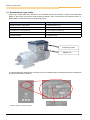
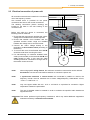
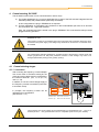
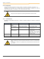
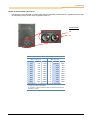
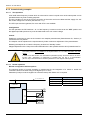
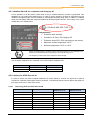
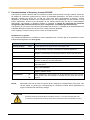
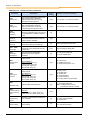
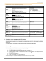
The DIP switches provide the possibility of carrying out commissioning without additional control units.
Additional settings are made using the potentiometer on the top of the frequency inverter.
As supplied, all DIP switches are at the “Off” position, which corresponds to control via the digital inputs.
The frequency setpoint value is adjusted via P1 and P2.
No.
Bit
Int RBrake
off
Behaviour corresponding to P555, P556, P557
2
Internal brake
resistor
on
Behaviour corresponding to the brake resistor
used
7
60Hz*
off
Motor data corresponding to the rated power of
the FI in kW relative to 50Hz, fmax = 50Hz
on
Motor data corresponding to the rated power of
the FI in hp relative to 60Hz, fmax = 60Hz
V/F
off
VFC regulation corresponding to P211/P212
Regulating
process
on
V/f curve ((⇒ P211=0 und P212=0)
off
off
off
on
on
off
on
on
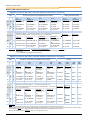
BUS
off
Corresponding to P509 and P510 [1] [2]
Source control
word and setpoint
value
on
System bus (⇒ P509=3 and P510=3)
off
off
Corresponding to P514 and 515 [32,
250kBaud]
off
on
Address 34, 250kBaud
on
off
Address 36, 250kBaud
on
on
Address 38, 250kBaud
8
7
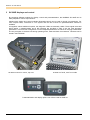
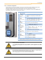
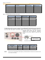
8‐pin DIP switch DIP switches
26
6
5
2
50/60Hz-operation
I/O
5/4
24/3
3
22
Plug‐in EEPROM 2/1
1/0
2
Potentiometer
function, digital
inputs and AS
interface
ADR
System bus
address/ baud rate
SK 200E, internal view Corresponding to P420 [1-4] and P400 [1-2]
or P480 [1-4] und P481 [1-4]
Further details in the next
(depends on the DIP3 "BUS")
table.
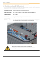
*) A changed setting is applied the next time the mains is switched on.
Existing settings in parameters P201-P209 and P105 are overwritten!
NOTE
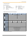
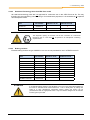
FACTORY SETTING, AS DELIVERED!
*) As delivered, all DIP switches are in the “off” position. Control is by means of the digital
control signals (P420 [01]-[04]) and the potentiometers P1 and P2 integrated in the FI (P400
[01]-[02]).
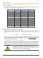
NOTE
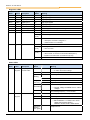
For controlling the frequency inverter via In/Out bits (e.g.: AS-i, DIG In 1 - 4) typical values are
preset in the relevant parameters (P480) and (P481). (Details: Section 5)
These settings apply to both control via AS-i bits and BUS I/O bits.
BU 0240 GB
21