1
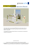
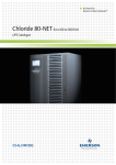
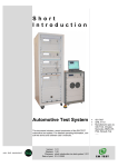
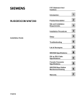
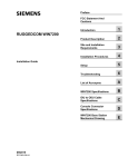
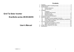
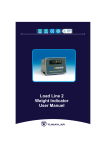
Industrial Power for
Business-Critical Continuity™
Emerson FP-60Z 5 to 60kVA
AC UPS system catalogue - FP-60Z31 and FP-60Z33
Emerson FP-60Z 5 to 60kVA
AC UPS system - FP-60Z31 and FP-60Z33
Scope
4
General Requirements
4
System overview
5
System description
6
Monitoring and Control Interface
9
Mechanical Data
14
Environmental Conditions
14
Technical Data of the Full Range
15
230 Vac Single Phase Output Technical Data
16
110 Vac Single Phase Output Technical Data
18
400 Vac Three Phase Ouptut Technical Data
20
220 Vac Three Phase Ouptut Technical Data
22
Parallel Operation
24
Options
26
General Arrangement Drawings
30
Emerson FP-60Z AC UPS
1 Scope
2 General Requirements
This document describes a continuous duty three phases Alternating
Current (AC) input, stand-alone,
three-phase or one-phase AC output
Uninterruptible Power System
(UPS).
2.1 ISO certification
All products from the Emerson
FP range include a wide choice of
ratings and a selection of industrialized and pre-configured options
to allow the product to be quickly
configured and delivered.
The FP-60Z AC UPS range is part of
Emerson’s know-how and long-time
relationship with industrial businesses. The range meets customers’
technical specifications for industrial
applications such as petrochemical
plants, oil and gas offshore developments (platforms, FPSO, etc…),
power generation plants, mining,
water desalination and treatment
plants, aluminium smelters, other
manufacturing plants (glass,
steel...).
The FP-60Z range is supported by a
range of services offered by Emerson Network Power. These services
can include, but are not limited to :
• Consultancy services
• Pre-engineering design and
support
• Project Management (contract
management, detailed engineering, documents for approval,
manufacturing, product testing,
witness-testing if requested, shipment, tailored user manual)
• Services (recommended commissioning spare parts, commissioning services, product lifetime
spare parts, hotline, trainings,
maintenance contracts, etc…)
4
Emerson Network Power is certified
as a company with a total quality
control system in accordance with
the ISO 9001.
2.2 Applied standards
The Emerson FP-60Z AC UPS
range shall have the CE mark in
accordance with the Safety and
EMC Directives 2006/95/EC and
2004/108/EC.
The Emerson FP-60Z range is designed and manufactured in accordance with the following international standards:
• IEC62040 Uninterruptible power
systems:
- IEC62040-1 General and safety
requirements for UPS
- IEC62040-2 Electromagnetic
compatibility (EMC) requirements
- IEC62040-3 Method of specifying the performance and test
requirements
- UPS classification as per
IEC62040-3: VFI-SS-111
• IEC60146 Semi conductor converters
• IEC60950 Safety of information
technology equipment including
electrical business equipment
• IEC60439 Low voltage switchgear
and control gear assemblies
• IEC60529 Degrees of protection
provided by enclosures (IP Code)
• IEC60076 Power transformers
• IEC60332-1-2 Tests on electric
and optical fibre cables under fire
conditions - Test for vertical flame
propagation for a single insulated
wire or cable – Procedure for 1 kW
pre-mixed flame
Emerson FP-60Z AC UPS
3 System overview
3.1 The system
Emerson FP-60Z is a state of art
static UPS system specially designed
for industrial applications. Block
schematic of the system is as shown
on Figure 1. The system operates
on a DSP controlled IGBT rectifier
and DSP-controlled PWM IGBTs
inverter. Emerson FP-60Z utilises
digital vector control technology
to optimise the performance of
the UPS. By adding system components, such as paralleling kits, safety
and disconnecting devices, distribution cubicles, as well as software
and communications solutions,
it is possible to set up elaborated
systems ensuring complete AC load
protection.
3.2 Models available
The UPS provides high quality AC
power for electronic equipment
loads. It offers the following features:
• Increased AC power quality
• Full input Power Factor Correction
(PFC) and very low THDi
• Full compatibility with all types of
loads
• Power blackout protection (for
systems associated with battery)
• Lifetime of, at least, 20 years,
combined with an appropriate
preventive maintenance
• Operation temperature of 0 to
40°C permanent.
The Emerson FP-60Z range includes
several kVA ratings output models
as specified in paragraphs 9 to 12.
It is of the single- or three-phase
output type.
UPS cubicle
-Q31
RESERVE
SUPPLY
Display
U
-Q21
U, F
-V21
RECTIFIER
U, I, F
INVERTER
-T11
-Q3
U, F
C
-V18
B
U, F, I, W
AC SUPPLY
3-PHASE
I,U
CHARGER-BOOSTER
-Q5
Battery
switch
A
-Q24
AC LOAD
1-PHASE
OR
3-PHASE
-Q21
Contact
A B C
Position
1 0 1
AUTO
1 0 1
TRANSITION
0 1 1
TEST
MAINTENANCE 0 1 0
BYPASS SWITCH OPERATION
BATTERY
Legend:
*
Interconnection cables not supplied by Chloride
Figure 1: Emerson FP-60Z Single Line Diagram
5
Emerson FP-60Z AC UPS
4 System description
In this section, the main power
electronic features and the operating modes of the Emerson FP-60Z
UPS range are described.
4.1 General description
The three-phase voltage taken from
the AC source is converter to a regulated DC voltage by DSP (Digital
Signal Processor) driven IGBT Rectifier. A transformer is provided at the
input of the rectifier as an optional
feature.
The charger-booster keeps the battery in a fully charged and optimum
operational condition.
The DC current taken from the rectifier is converted to a sinusoidal and
regulated AC voltage by an IGBTs
inverter (Insulated Gate Bipolar
Transistor), using PWM (Pulse Width
Modulation). This means that the
digital signal processor controls the
IGBTs so that the DC input voltage is
divided into pulsed voltage to generate a low distortion sinewave AC
output voltage with good transient
response voltage regulation.
A transformer is provided at the
output of the inverter bridge.
4.2
Components
As standard, the UPS consists of the
following major components:
• One input isolator
• One IGBT rectifier
One IGBT charger-booster
One IGBT inverter
• One output transformer
• Electronic static switches
• Manual bypass switch
• Two control units, each based
on one microprocessor and one
Digital Signal Processor-DSP
• One control and visualisation unit
(LCD touch pad colour display)
4.3 Operating modes
synchronised and does not cause an
interruption to the load.
The Emerson FP-60Z UPS operates
as follow:
4.3.2. Overload operation
The UPS inverter is considered in
overload conditions when the load
is beyond 105% of the inverter
nominal rating.
4.3.1. Normal operation
The critical AC load is continuously
supplied by the UPS inverter. The
rectifier derives power from the
AC source and converts it into DC
power for the inverter. Battery
charger takes power from rectifier
output and maintains the battery in
a fully charged and optimum operational condition (floating mode).
• Upon overload detection by the
UPS inverter, the static switch
automatically transfers the load to
reserve supply. The static switch
automatically switches back the
load to inverter after the load is
back to normal.
The inverter converts the DC power
into clean and regulated AC power
to supply the critical load through
the static transfer switch. The power
loading can reach up to 105% of
the inverter nominal rating without
considering the inverter in overload
conditions.
• Upon overload detection by the
UPS inverter (above 110% and up
to 125% of the inverter nominal
rating):
- The system initiates a timer for a
10 minutes period.
- The AC load remains powered
by the UPS inverter for this 10
minutes period.
- Upon expiration of the 10
minutes delay, the UPS inverter
shuts down and load is transferred
to reserve supply.
- The AC load remains powered
by the reserve static switch for
While supplying the load, the inverter and static switch control unit
monitors the reserve supply signal
and ensures that the inverter bridge
tracks the reserve supply frequency.
Thus, any automatic transfer to
the reserve supply (e.g. when an
overload is detected) is frequency
time (s)
10 min
100 s
1 min
10 s
5s
100
125
150
Figure 2: Inverter overload withstanding curve
6
Overload (in %)
Emerson FP-60Z AC UPS
further 10 minutes period.
- Upon expiration of the 10
minutes delay, the UPS reserve
static switch shuts down.
• Upon overload detection by the
UPS inverter (above 125% and up
to 150% of the inverter nominal
rating):
- The system initiates a timer for a
1 minute period.
- The AC load remains powered by
the UPS inverter for this 1 minute
period.
- Upon expiration of this minute
delay, the inverter shuts down
and load is transferred to reserve
supply.
- The AC load remains powered
by the reserve static switch for
further 1 minute period.
- Upon expiration of the 1 minute
delay, the UPS reserve static
switch shuts down.
• Upon overload detection by the
UPS inverter above 150% of the
inverter nominal rating:
- The UPS inverter keeps powering the AC load for 5 seconds
after which it automatically shuts
down.
This overload operation mode is
shown in Figure 2.
4.3.3.
Input supply failure
Upon fault of the input AC source,
the rectifier stops while the load remains supplied by the UPS inverter.
Upon Mains input fault detection,
the inverter immediately draws its
power from the associated battery
through the booster. While the
inverter is powered by the battery
through the booster, indication is
provided of the discharging status.
When reaching the end of battery
autonomy, an alarm occurs and the
static switch immediately switches
the load onto reserve supply, wit-
hout interruption. If for any reason,
the reserve supply is not present or
faulty and the battery is no longer
available, the UPS automatically
shuts down.
4.3.4.
Battery recharge
operation
After an AC input failure and upon
its restoration, the charger-booster
automatically recharges the associated battery.
The selection of the optimum
charging method will be completely
managed by the microprocessor.
Several different charging methods
are available and are defined at the
project stage.
4.3.5.
Maintenance bypass
operation
If for any reason the UPS has to be
taken out of service for maintenance
or repair, the Emerson FP-60Z UPS
is provided with a manual bypass
switch. The bypass switch enables
a load transfer to reserve supply
without power interruption for the
load. Bypass isolation is then complete, all serviceable components
such as fuses, power modules etc.
are isolated.
The transfer/retransfer is based on
the make-before-break principle
in order to secure the critical load:
the transfer/retransfer operation
is automatically accomplished by
paralleling and synchronising the
inverter output to the reserve supply, before closing or opening the
bypass switch as appropriate.
4.4 Electrical features
4.4.1.
Total Input Harmonic
Distortion (THD) and
Input Power Factor (PF)
The maximum voltage THD (THDv)
permitted on the rectifier input
(either from the utility or generator)
will be 10% (normal operation is
guaranteed up to 8%). The maximum current THD injected into the
mains (THDi) will be less than 3% at
maximum input power and input
voltage THDv < 1% (nominal input
voltage and current). The input
power factor (PF) will be up to 0.98.
Under other input conditions and
with other output load fractions the
THDi will be < 5%. This means that
the Emerson FP-60Z will be seen
by the primary mains sources and
distribution as a resistive load (i.e.
it will absorb only active power and
the current waveform will be practically sinusoidal), thus ensuring total
compatibility with any power source
and minimizing OPEX costs.
4.4.2.
Operation with diesel
generator
In order to obtain the required THD
on input voltage, the coordination
between a diesel generator and UPS
will be based on the generator’s sub
transient reactance, as opposed to
its short-circuit reactance.
4.4.3. Battery charging modes
The battery charger will be operable
with the following types of batte7
Emerson FP-60Z AC UPS
ries:
• Sealed Lead Acid
• Lead Acid (VRLA)
• Nickel Cadmium
The selection of the optimum
charging method will be completely
managed by the microprocessor.
4.4.4.
Temperature compensated battery charging
In order to ensure optimum battery
charging, float voltage will be automatically adjusted to the ambient
temperature. The IGBT rectifier will
be capable of supplying the battery
charger with DC voltage at rated
power, even if the UPS input AC voltage is below the nominal voltage
specified. A further reduction of the
input AC voltage (within specified
limits) will inhibit the battery charger but will not require the discharging of the batteries.
4.4.5.
Output voltage harmonic
distortion
The inverter provides harmonic
neutralisation and filtering to limit
the total harmonic distortion on the
voltage to less than 2% with a linear
load. For reference non-linear load
(as defined by IEC/EN62040-3) the
THD will be limited to less than 5%.
Inverter short-circuit
capacity
The inverter short circuit capacity of
Emerson FP-60Z for the first 100ms
will be 250% RMS for any short
circuit configuration. After the first
100ms, it will limit the current to
150% for no longer than 5s and then
it will shut down. The short-circuit
capacity on the output of Emerson
FP-60Z is detailed in Figure 3.
4.4.7.
Static Switch
overload capacity
The bypass static switch will be
capable of supporting the following
overloads:
• 125% for 10 minutes
• 150% for 1 minute
• 700% for 600 milliseconds
• 1000% for 100 milliseconds
t (ms)
10000
5s
1000
4.4.6.
100 ms
10
1.5
Figure 3: 1-ph & 3-ph inverter short circuit capacity
8
3
2
1
2.5
4
In (A)
Emerson FP-60Z AC UPS
5 Monitoring and Control Interface
The UPS incorporates the necessary
controls, instruments and indicators
to allow the operator to monitor the
system status and performance and
take any appropriate action. Furthermore, interfaces are available
upon request, which allow extended
monitoring and control, as well as
service functions.
5.1 Touch Pad
The Emerson FP-60Z control panel
includes a backlit touch-pad color
Liquid Crystal Display for complete UPS monitoring and control.
Complete access to all LCD menus is
possible through navigation buttons
located on the touch-pad screen.
After 30 seconds of inactivity (i.e.
without buttons being pressed) the
display reverts to the default page.
5.2 Main screen
The main screen shall display an
active mimic diagram of the UPS
(see Figure 4). This screen may also
display the main input/output cur-
rents and voltages values (if configured to do so via the menus).
The active mimic diagram displays
the following information:
• Graphical view of the power flow
• Graphical view of the status of
each functional block (red/yellow/
green/grey) depending on each
block state (alarm, warning, ok)
• Graphical view of the systems
isolators.
5.3 Light emitting diodes
(LEDs)
The UPS includes 3 external Light
Emitting Diodes (LEDs) to indicate
the overall system operation status
Figure 4: Emerson FP-60Z UPS– Local Human-Machine Interface (HMI)
9
Emerson FP-60Z AC UPS
Symbol
Colour
Green
Green flashing
Yellow
Red
Description
Normal Operation
When this light is on (not flashing), the system is running normally and neither warnings
nor alarms are present.
During mains failures (all other conditions being at nominal level), this LED will flash.
Warning Condition(s) present
This indication will be activated by the presence of anomalous conditions, which could
affect the nominal functioning of the UPS. These conditions are not originated with
the UPS, but may be caused either by the surrounding environment or by the electrical
installation (mains side and load side). It will be possible to read the description of the
active warning(s) by browsing the relevant LCD display menus.
Alarm Condition
When this light is on, immediate attention should be given to the severity of the alarm,
and service should be called promptly. It will be possible to read the description of the
active alarm(s) by browsing the relevant LCD display menus.
Figure 5: Light Emitting Diodes (LED) description
as well as the condition of the
functional blocks. LEDs operation is
described in Figure 5.
These LEDs shall interact with the
active mimic diagram displayed on
the graphical display (see Figure 6).
5.4 Start and Stop push
buttons
The Start and Stop push buttons
are integrated into the mimic panel
board, and have the following
predefined functions:
The control will incorporate a safety
feature to prevent inadvertent
operation yet still allow for rapid
shutdown in the event of an emergency.
This is achieved by pressing the
«STOP» button of the appropriate
module (Rectifier or Inverter) and by
confirming in the pop-up window
which appears. See Figure 7.
Figure 6: Example of UPS fault condition on all modules
10
Figure 7: Start/stop Rectifier function
Emerson FP-60Z AC UPS
5.5 Access to UPS
information
5.5.1. Block Information
By touching the appropriate
functional block of the single line
diagram, it is possible to access to
the relevant block information:
• Measures
• Status
• Active warnings and alarms, if any.
An example is provided on Figure 8.
5.5.2. Measures
A dedicated page holds the full set
of measurements for each functional block (rectifier, bypass, booster/
charger, batteries, inverter and
load).
An example is shown on Figure 9.
5.5.3. Warning/Faults
This page contains information
regarding various anomalies concerning power converters such as the
bypass, rectifier, inverter and booster charger. In addition to this there
is also warning and fault information
relating to the battery and the load.
This window is shown on Figure 10.
5.5.4. Event Logger
The display board can store all the
events that took place on the UPS.
The event log screen allows to
display all the faults, warnings or
status changes, that has appeared
or disappeared on the UPS internal
CAN Bus.
An event log will show the last 2000
events that appeared on the UPS.
These events are ordered by date.
A reset event log function available
for the customer on the display
enables to cancel the current recordings.
See Figure 11 for an example of Evet
Lgger page.
Figure 8: Block status information page (Rectifier example)
Figure 10: Warning / faults page (example)
Figure 9: Block Measures page (Load example)
Figure 11: Event logger page (example)
11
Emerson FP-60Z AC UPS
5.5.5.
Event Log
Export function
All the events recorded can be
downloaded on an USB key, as
shown on Figure 13. By this way,
it is possible to get the events on a
tabular format file without having to
connect any maintenance tool.
5.6 Remote signalling and
control signal
5.6.1.
Logic outputs for remote
indications
The Emerson FP-60Z is able to
deliver several output information.
These output information are made
available on double-pole changeover (dpco) contacts (8A/250V AC1;
8A/30V DC1; 1A/60V DC1).
The following information is made
available on voltage-free contacts:
• UPS general alarm
• Charger fault
• Inverter fault
• Reserve supply fault
• Load on reserve
• Imminent shutdown
Connection of the customer cables
is achieved on the identified, screwclamp terminal blocks of each relayholder.
5.6.2. Logic inputs
The Emerson FP-60Z range allows
the signalisation of specific alarms
from the customer’s environment
and eventually takes the appropriate action on the UPS thanks to
dedicated logic inputs.
As standard, the UPS includes the
following input:
• Emergency power off
Figure 12: Event Log export function
Among all possible function, the
following logic input can be wired
upon request:
• Remote control on/off
5.7 Communication interfaces (options)
Upon request, The Emerson FP-60Z
can be equipped with a communication board offering either RS232
serial or RS485 serial communication, as shown onFigure 15.
5.7.1. Isolated RS 232 link
The communication board of the
Emerson FP-60Z includes one sub-D
9 points connector for direct (1
master, 1 slave, max 15 meters)
serial RS232 communication.
Shield
54
9 83 2
7 61
Figure 13: RS 232 D-Sub 9 points connector
12
Pin assignment is described in the
Table hereafter.
Pin Signal
Explanation
1
Not used
2
Tx
Transmission RS232
3
Rx
Reception RS232
4
Not used
5
RS232 GND Signal ground
6
Not used
7
RTS
Clear to send RS232
8
Not used
9
Not used
Table 1: RS232 pin assignment
NOTE:
If simultaneous use of RS232 port
and RS 485 is necessary, this will
require 2 separate PCBs, one for
RS232 and the other for RS485.
5.7.2. Isolated RS 485 link
The communication board of the
Emerson FP-60Z also includes one
6 points socket for multipoint (1
master, up to 31 slaves, max 1300
meters) serial RS485 communication.
Customer connection is easily
achieved thanks to the screwclamp connector provided (see
figure below). Earth connection is
Emerson FP-60Z AC UPS
12
34
5
6
Figure 14: RS 485 6-points connector
Figure 15: Serial Communication board
achieved on the PCB through a 6.35
Faston lug.
5.7.3. Ethernet RJ45 Interface
The Emerson FP-60Z is equipped
with a RJ45 Ethernet interface accessible on the back of the display unit.
This interface is a 10/100 MBit auto
negotiation full/half duplex RJ45
Ethernet interface for LAN communication with service software
PPVis. It allows the setup of UPS
parameters during commissioning
and maintenance.
The RS485 communication path
may be used either in 4 wires mode
or in 2 wires mode, as described in
the Table 2 hereafter.
4-wires
mode
1
GND
Not used
Transmission
2
TxRS485/ neg.
Transmission
3
Tx+
RS485/ pos.
Reception
4
RxRS485/ neg.
Reception
5
Rx+
RS485/ pos.
6
+5V
Not used
Table 2: RS 485 pin assignment
Pin
Signal
2-wires
mode
Not used
Negative
signal
Positive
signal
Not used
Not used
Not used
13
Emerson FP-60Z AC UPS
6 Mechanical Data
6.1 Enclosure
The Emerson FP-60Z UPS is housed
in a space-saving enclosure including front doors and removable
panels (standard external protection IP 42). The enclosure is made
of sheet steel. The doors can be
locked. The enclosure is of the floor
mounted type.
6.2 Ventilation
Fan-assisted air cooling is standard
on the Emerson FP-60Z range. The
cooling air entry is on the front
door and in the base. The air exit
is at the top of the device. It is
recommended that the enclosure
is installed with at least 400 mm
of free space between device and
ceiling at the top in order to allow an
unhindered cooling air exit.
6.3 Cable entry
Cable entry is achieved via the bottom of the cabinet. Top cable entry
is also available in option.
6.4 Enclosure design
All the surfaces of the enclosure are
finished with an electrostatically
applied powder-epoxy-polyester
coat, cured at high temperature.
The coating has a thickness of 70
microns (+/-10). Colour of the
enclosure is RAL 7035 (light grey)
textured semi-gloss.
For uniformity of the UPS with other
equipments in electrical rooms, the
surface finishing and the colour of
the enclosure may be tailored according to the customer’s specification
and upon request.
6.5 Components
identification
Main components are identified by
PVC label stickers as standard (black
characters on white background).
6.6 Cabling
Internal cabling is made of PVC
cables as per UL 1015. Halogen-free
cables (as per IEC 332-1-2) is available as an option.
6.7 Internal cables
connection
Connection of cables is achieved by
inserting cables directly in screwclamps.
Auxiliary cables include ferrules.
6.8 Access to integrated
subassemblies
All internal subassemblies are accessible for typical and most frequent
maintenance from the front of the
unit. Top access is available for
replacement of cooling fans. Rear
access is not required for installation
or servicing. In any case and if side
or rear access is required, the side
and rear panels are removable.
6.9 Installation
The UPS is forkliftable from the
front. Upon request, it can be equipped with lifting lugs to facilitate its
installation on site.
7 Environmental Conditions
The Emerson FP-60Z UPS is capable
of withstanding any combination of
the following environmental conditions. It operates without mechanical or electrical damage or degradation of operating characteristics.
14
7.1 Ambient temperature
The UPS is capable of operating
permanently from 0° to 40°C.
7.2 Relative humidity
The UPS is capable of withstanding
up to 95% humidity level (noncondensing) for an ambient temperature of 20°C.
7.3 Altitude
The maximum altitude without
derating is 1000 metres above sea
level.
For use of the system at an altitude
above 1000m and up to 2000m, a
derating factor of 1% per 100m will
be applied. Please consult us for
further information.
Emerson FP-60Z AC UPS
8 Technical Data of the Full Range
Data common to the complete Emerson CP-60Z AC UPS range
Rectifier input
Nominal input voltage
Input phases
Input voltage tolerance
Nominal Frequency
Tolerance on frequency
Rectifier type
Input power factor
Soft start
Inrush current
Isolation transformer
Maximum allowed voltage distortion (THD) from Mains
(or generator) on the input of the rectifier
Charger output
DC voltage stability
DC ripple voltage (without battery)
(V)
(%)
400 [380, 415]
3ph + N
+10 / -10 (with 400V input) (max tolerated +15 / -20)
50 / 60 (factory setting selectable)
+5 / -5
IGBT (Insulated Gate Bipolar Transistors)
Up to 0.98
10 (1 to 90 factory setting selectable)
≤ 1 (without input transformer) / ≤ 8 (with input transformer option)
Optional
8
(%)
(% RMS)
+/- 1
≤1
(%)
(Hz)
(%)
(s)
(x In)
Inverter output
Nominal output voltage
Nominal output frequency
Overload at cos phi = 0.8
Isolating transformer
Short circuit capacity (1-ph & 3-ph output)
Voltage stability (for 100% load variation):
- Static
- Dynamic
Frequency stability:
- with own oscillator
- with reserve supply synchronisation
Harmonic voltage distortion:
- with 100% linear load
- with 100% non linear load
Output crest factor admissible
Load power factor operation range
Reserve supply input
Reserve input voltage
Reserve input voltage tolerance
Reserve input frequency
Reserve input frequency tolerance
(%)
See tables on the following pages
50 / 60 [factory setting selectable]
125 (10 min) / 150 (1 min)
Standard
250 (100 ms) / 150 (5 s)
(%)
(%)
+/- 1
VFI SS 111 - Complies with IEC/EN 62040-3, class 1
(%)
(%)
+/- 0.1
+/- 1 [adjustable from 1 to 4]
(%)
(%)
<2
≤5 (non linear load defined by IEC 62040-3)
3/1
0.5 lag to 0.5 lead
(V)
(%)
(Hz)
(%)
See tables on the following pages
+/- 10 [adjustable from +/-5% to +/-15%]
50 / 60 [factory setting selectable]
+/- 1 [adjustable from +/-1% to +/-4%]
(years)
IP 42
IP 20
Bottom (top optional)
From front (except transformers, if present)
20
(°C)
(°C)
(%)
(m)
0 to 40
-20 to +70
<90
<1000 (without system derating)
(Hz)
(%)
System data
External protection degree
Internal protection degree
Cable entry
Accessibility to components
System design life
Environmental Data
Operating temperature
Storage temperature
Maximum relative humidity (at 20°C non condensing)
Operating altitude
The technical data enclosed is for general information. This publication is issued to provide outline information only and is not deemed to form any part of any offer or contract. The company has a
policy of continuous improvement and we therefore reserve the right to vary any information without prior notice.
15
Emerson FP-60Z AC UPS
9 230 Vac Single Phase Output Technical Data
Emerson FP-60Z 31E
Battery voltage:
Output voltage:
Ratings
110 VDC
230 VAC [220, 240] - 1 phase
(kVA)
5
10
20
UPS input
Input voltage
Rectifier technology
Nominal input voltage, frequency, tolerances
Max current consumption @ 3x400VAC supply (5)
Current consumption (battery in floating) (5)
Recommended type for UPS input protection
(A)
(A)
Battery
Battery nominal voltage
Battery voltage range
Recommended number of cells (VRLA)
Recommended number of cells (WET)
Recommended number of cells (NiCd)
Battery recharge current available (up to)
(V)
(V)
Nominal output voltage AC
Output voltage tolerance
Nominal output frequency
Nominal output current at full load (cos phi 0.8) and nominal output voltage
(V)
(%)
(Hz)
(A)
230 [220, 240] – 1 phase + neutral
+/- 1%
50 [60]
22
43
87
Nominal voltage AC
Nominal frequency
Frequency tracking range
Recommended type for reserve input protection
(V)
(Hz)
(%)
230 [220, 240] – 1 phase + neutral
50 [60]
+/- 3%
D curve (circuit breakers)
UPS output
Reserve static switch
(A)
UPS System data (Single)
Heat dissipation system
UPS system losses in floating at full load and nominal output voltage (for air cond. calculation)
AC/AC efficiency 100% load (1)(4)
AC/AC efficiency 100% load (1)(5)
UPS system noise
Height
Width (UPS with integrated manual bypass switch)
Depth
Footprint (UPS with integrated manual bypass switch)
Weight (UPS with integrated manual bypass switch) (5)
Drawing code
(W)
(%)
(%)
(dB)
(mm)
(mm)
(mm)
(m²)
(kg)
Special Configurations
By-pass cubicle with reserve transformer
- Width
- Weight
Dual distributed with 1 reserve line
- Width (UPS + bypass with reserve transf. + UPS)
Dual distributed with 2 reserve lines
- Width
NOTES:
-(1) For tolerance, see IEC 60146-1-1. System’s efficiency varies according to configurations and options
-(2) For 3x400VAC Mains within the +/-10% limits
-(3) For 3x400VAC Mains nominal
-(4) With output transformer only
-(5) With both input & output transformer
110
88 – 170 (2)
54 – 72
53 – 63
88 – 98
26
13
52
forced cooling with
redundant monitored fans
1063
1639
2824
80.5
84.5
86.5
79
83
85
61
62
64
2052
2052
2052
800
800
800
815
815
815
0.65
0.65
0.65
350
390
515
see paragraph ‘General Arrangement’
E0
E0
E0
natural
Code for general arrangement
16
400 VAC [380, 415] three phase
IGBT
See common data
10
20
39
7
14
27
D curve (circuit breakers)
(mm)
(kg)
400
145
400
165
600
235
(mm)
800+600+800
800+600+800
800+600+800
(mm)
Width of a single unit x2
Emerson FP-60Z AC UPS
220 VDC
230 VAC [220, 240] - 1 phase
10
20
14
20
30
40
400 VAC [380, 415] three phase
IGBT
See common data
39
57
27
40
D curve (circuit breakers)
220
177 – 340 (2)
108 – 144
106 – 125
176 – 200
39
75
53
60
110
77
40
60
400 VAC [380, 415] three phase
IGBT
See common data
75
110
53
77
D curve (circuit breakers)
400
320 – 550 (2)
192 – 228
192 – 204
320 – 323
13
26
43
230 [220, 240] – 1 phase + neutral
+/- 1%
50 [60]
87
130
174
1639
84.5
83
62
2052
800
815
0.65
400
400 VDC
230 VAC [220, 240] - 1 phase
52
77
261
50
75
230 [220, 240] – 1 phase + neutral
+/- 1%
50 [60]
174
261
230 [220, 240] – 1 phase + neutral
50 [60]
+/- 3%
D curve (circuit breakers)
230 [220, 240] – 1 phase + neutral
50 [60]
+/- 3%
D curve (circuit breakers)
forced cooling with redundant monitored fans
forced cooling with redundant monitored fans
2824
3586
4364
86.5
88.5
89.5
85
87
88
64
65
65
2052
2052
2052
800
800
1000
815
815
815
0.65
0.65
0.80
500
550
590
see paragraph ‘General Arrangement’
E0
E0
F0
5333
91.5
90
66
2052
1200
815
0.96
650
400
165
600
235
600
265
600
280
800
370
600
345
800
480
800+600+800
800+600+800
800+600+800
1000+600+1000
1200+800+1200
1000+600+1000
1200+800+1200
E0
Width of a single unit x2
G0
4364
5333
89.5
91.5
88
90
62
64
2052
2052
1000
1200
815
815
0.80
0.96
600
670
see paragraph ‘General Arrangement’
F0
G0
Width of a single unit x2
The technical data enclosed is for general information. This publication is issued to provide outline information only and is not deemed to form any part of any offer or contract. The company has a
policy of continuous improvement and we therefore reserve the right to vary any information without prior notice.
17
Emerson FP-60Z AC UPS
10 110 Vac Single Phase Output Technical Data
Emerson FP-60Z 31E
Battery voltage:
Output voltage:
Ratings
110 VDC
110 VAC [115, 120] - 1 phase
(kVA)
UPS input
Input voltage
Rectifier technology
Nominal input voltage, frequency, tolerances
Max current consumption @ 3x400VAC supply (5)
Current consumption (battery in floating) (5)
Recommended type for UPS input protection
(A)
(A)
Battery
10
20
400 VAC [380, 415] three phase
IGBT
See common data
11
20
39
7
14
28
D curve (circuit breakers)
110
88 – 170 (2)
54 – 72
53 – 63
88 – 98
26
Battery nominal voltage
Battery voltage range
Recommended number of cells (VRLA)
Recommended number of cells (WET)
Recommended number of cells (NiCd)
Battery recharge current available (up to)
(V)
(V)
Nominal output voltage AC
Output voltage tolerance
Nominal output frequency
Nominal output current at full load (cos phi 0.8) and nominal output voltage
(V)
(%)
(Hz)
(A)
110 [115, 120] – 1 phase + neutral
+/- 1%
50 [60]
45
91
182
Nominal voltage AC
Nominal frequency
Frequency tracking range
Recommended type for reserve input protection
(V)
(Hz)
(%)
110 [115, 120] – 1 phase + neutral
50 [60]
+/- 3%
D curve (circuit breakers)
UPS output
Reserve static switch
(A)
UPS System data (Single)
Heat dissipation system
UPS system losses in floating at full load and nominal output voltage (for air cond. calculation)
AC/AC efficiency 100% load (1)(4)
AC/AC efficiency 100% load (1)(5)
UPS system noise
Height
Width (UPS with integrated manual bypass switch)
Depth
Footprint (UPS with integrated manual bypass switch)
Weight (UPS with integrated manual bypass switch) (5)
Drawing code
(W)
(%)
(%)
(dB)
(mm)
(mm)
(mm)
(m²)
(kg)
Special Configurations
By-pass cubicle with reserve transformer
- Width
- Weight
Dual distributed with 1 reserve line
- Width (UPS + bypass with reserve transf. + UPS)
Dual distributed with 2 reserve lines
- Width
NOTES:
-(1) For tolerance, see IEC 60146-1-1. System’s efficiency varies according to configurations and options
-(2) For 3x400VAC Mains within the +/-10% limits
-(3) For 3x400VAC Mains nominal
-(4) With output transformer only
-(5) With both input & output transformer
13
52
forced cooling with
redundant monitored fans
1128
1756
3048
79.5
83.5
85.5
78
82
84
61
62
64
2052
2052
2052
800
800
800
815
815
815
0.65
0.65
0.65
350
395
515
see paragraph ‘General Arrangement’
E0
E0
E0
natural
Code for general arrangement
18
5
(mm)
(kg)
400
145
400
165
600
235
(mm)
800+600+800
800+600+800
800+600+800
(mm)
Width of a single unit x2
Emerson FP-60Z AC UPS
220 VDC
110 VAC [115, 120] - 1 phase
10
20
14
20
30
40
400 VAC [380, 415] three phase
IGBT
See common data
39
57
28
40
D curve (circuit breakers)
220
177 – 340 (2)
108 – 144
106 – 125
176 – 200
39
76
53
60
112
78
40
60
400 VAC [380, 415] three phase
IGBT
See common data
76
112
53
78
D curve (circuit breakers)
400
320 – 550 (2)
192 – 228
192 – 204
320 – 323
13
26
91
110 [115, 120] – 1 phase + neutral
+/- 1%
50 [60]
182
273
364
1756
83.5
82
62
2052
800
815
0.65
390
400 VDC
110 VAC [115, 120] - 1 phase
52
77
545
50
75
110 [115, 120] – 1 phase + neutral
+/- 1%
50 [60]
364
545
110 [115, 120] – 1 phase + neutral
50 [60]
+/- 3%
D curve (circuit breakers)
110 [115, 120] – 1 phase + neutral
50 [60]
+/- 3%
D curve (circuit breakers)
forced cooling with redundant monitored fans
forced cooling with redundant monitored fans
3048
3650
4782
85.5
87.5
88.5
84
86
87
64
65
65
2052
2052
2052
800
800
1000
815
815
815
0.65
0.65
0.80
505
620
950
see paragraph ‘General Arrangement’
E0
E0
F0
5933
90.5
89
66
2052
1200
815
0.96
1090
400
165
600
235
800
280
800
300
1200
425
800
300
1200
425
800+600+800
800+600+800
800+800+800
1000+800+1000
1200+1200+1200(4)
1000+800+1000
1200+1200+1200(4)
E0
Width of a single unit x2
G0
4782
5933
88.5
90.5
87
89
62
64
2052
2052
1000
1200
815
815
0.80
0.96
925
1065
see paragraph ‘General Arrangement’
F0
G0
Width of a single unit x2
The technical data enclosed is for general information. This publication is issued to provide outline information only and is not deemed to form any part of any offer or contract. The company has a
policy of continuous improvement and we therefore reserve the right to vary any information without prior notice.
19
Emerson FP-60Z AC UPS
11 400 Vac Three Phase Ouptut Technical Data
Emerson FP-60Z 33E
Battery voltage:
Output voltage:
Ratings
110 VDC
400 VAC [380, 415]- 3 phases
(kVA)
UPS input
Input voltage
Rectifier technology
Nominal input voltage, frequency, tolerances
Max current consumption @ 3x400VAC supply (5)
Current consumption (battery in floating) (5)
Recommended type for UPS input protection
(A)
(A)
Battery
5
10
20
400 VAC [380, 415] three phase
IGBT
See common data
11
20
39
7
14
27
D curve (circuit breakers)
110
88 – 170 (2)
54 – 72
53 – 63
88 – 98
26
Battery nominal voltage
Battery voltage range
Recommended number of cells (VRLA)
Recommended number of cells (WET)
Recommended number of cells (NiCd)
Battery recharge current available (up to)
(V)
(V)
Nominal output voltage AC
Output voltage tolerance
Nominal output frequency
Nominal output current at full load (cos phi 0.8) and nominal output voltage
(V)
(%)
(Hz)
(A)
400 [380, 415] – 3 phases + neutral
+/- 1%
50 [60]
7
14
29
Nominal voltage AC
Nominal frequency
Frequency tracking range
Recommended type for reserve input protection
(V)
(Hz)
(%)
400 [380, 415] – 3 phases + neutral
50 [60]
+/- 3%
D curve (circuit breakers)
UPS output
Reserve static switch
(A)
13
52
UPS System data (Single)
Heat dissipation system
UPS system losses in floating at full load and nominal output voltage (for air cond. calculation)
AC/AC efficiency 100% load (1)(4)
AC/AC efficiency 100% load (1)(5)
UPS system noise
Height
Width (UPS with integrated manual bypass switch)
Depth
Footprint (UPS with integrated manual bypass switch)
Weight (UPS with integrated manual bypass switch) (5)
Drawing code
(W)
(%)
(%)
(dB)
(mm)
(mm)
(mm)
(m²)
(kg)
Code for general arrangement
Special Configurations
By-pass cubicle with reserve transformer
- Width
- Weight
Dual distributed with 1 reserve line
- Width (UPS + bypass with reserve transf. + UPS)
Dual distributed with 2 reserve lines
- Width
NOTES:
-(1) For tolerance, see IEC 60146-1-1. System’s efficiency varies according to configurations and options
-(2) For 3x400VAC Mains within the +/-10% limits
-(3) For 3x400VAC Mains nominal
-(4) With output transformer only
-(5) With both input & output transformer
20
forced cooling with
redundant monitored fans
1096
1697
2935
80
84
86
78.5
82.5
84.5
61
62
64
2052
2052
2052
800
800
800
815
815
815
0.65
0.65
0.65
350
400
500
see paragraph ‘General Arrangement’
E0
E0
E0
natural
(mm)
(kg)
600
170
600
190
600
245
(mm)
800+600+800
800+600+800
800+600+800
(mm)
Width of a single unit x2
Emerson FP-60Z AC UPS
220 VDC
400 VAC [380, 415] - 3 phases
10
20
14
20
30
40
400 VAC [380, 415] three phase
IGBT
See common data
39
57
27
40
D curve (circuit breakers)
220
177 – 340 (2)
108 – 144
106 – 125
176 – 200
39
76
53
400 VDC
400 VAC [380, 415] - 3 phases
60
111
78
60
400 VAC [380, 415] three phase
IGBT
See common data
76
111
53
78
D curve (circuit breakers)
400
320 – 550 (2)
192 – 228
192 – 204
320 – 323
13
26
14
400 [380, 415] – 3 phases + neutral
+/- 1%
50 [60]
29
43
58
52
77
87
400 [380, 415] – 3 phases + neutral
50 [60]
+/- 3%
D curve (circuit breakers)
50
75
400 [380, 415] – 3 phases + neutral
+/- 1%
50 [60]
58
87
400 [380, 415] – 3 phases + neutral
50 [60]
+/- 3%
D curve (circuit breakers)
forced cooling with redundant monitored fans
1697
84
82.5
62
2052
800
815
0.65
400
40
forced cooling with redundant monitored fans
2935
3746
4571
86
88
89
84.5
86.5
87.5
64
65
65
2052
2052
2052
800
800
1000
815
815
815
0.65
0.65
0.80
500
550
590
see paragraph ‘General Arrangement’
E0
E0
F0
5631
91
89.5
66
2052
1200
815
0.96
650
600
190
600
245
600
285
600
320
800
405
600
320
800
405
800+600+800
800+600+800
800+600+800
1000+600+1000
1200+800+1200
1000+600+1000
1200+800+1200
E0
Width of a single unit x2
G0
4571
5631
89
91
87.5
89.5
62
64
2052
2052
1000
1200
815
815
0.80
0.96
570
630
see paragraph ‘General Arrangement’
F0
G0
Width of a single unit x2
The technical data enclosed is for general information. This publication is issued to provide outline information only and is not deemed to form any part of any offer or contract. The company has a
policy of continuous improvement and we therefore reserve the right to vary any information without prior notice.
21
Emerson FP-60Z AC UPS
12 220 Vac Three Phase Ouptut Technical Data
Emerson FP-60Z 33E
Battery voltage:
Output voltage:
Ratings
110 VDC
220 VAC [190, 208]- 3 phases
(kVA)
UPS input
Input voltage
Rectifier technology
Nominal input voltage, frequency, tolerances
Max current consumption @ 3x400VAC supply (5)
Current consumption (battery in floating) (5)
Recommended type for UPS input protection
(A)
(A)
Battery
5
10
20
400 VAC [380, 415] three phase
IGBT
See common data
11
20
40
7
14
28
D curve (circuit breakers)
110
88 – 170 (2)
54 – 72
53 – 63
88 – 98
26
Battery nominal voltage
Battery voltage range
Recommended number of cells (VRLA)
Recommended number of cells (WET)
Recommended number of cells (NiCd)
Battery recharge current available (up to)
(V)
(V)
Nominal output voltage AC
Output voltage tolerance
Nominal output frequency
Nominal output current at full load (cos phi 0.8) and nominal output voltage
(V)
(%)
(Hz)
(A)
220 [190, 208] – 3 phases + neutral
+/- 1%
50 [60]
13
26
52
Nominal voltage AC
Nominal frequency
Frequency tracking range
Recommended type for reserve input protection
(V)
(Hz)
(%)
220 [190, 208] – 3 phases + neutral
50 [60]
+/- 3%
D curve (circuit breakers)
UPS output
Reserve static switch
(A)
13
52
UPS System data (Single)
Heat dissipation system
UPS system losses in floating at full load and nominal output voltage (for air cond. calculation)
AC/AC efficiency 100% load (1)(4)
AC/AC efficiency 100% load (1)(5)
UPS system noise
Height
Width (UPS with integrated manual bypass switch)
Depth
Footprint (UPS with integrated manual bypass switch)
Weight (UPS with integrated manual bypass switch) (5)
Drawing code
(W)
(%)
(%)
(dB)
(mm)
(mm)
(mm)
(m²)
(kg)
Code for general arrangement
Special Configurations
By-pass cubicle with reserve transformer
- Width
- Weight
Dual distributed with 1 reserve line
- Width (UPS + bypass with reserve transf. + UPS)
Dual distributed with 2 reserve lines
- Width
NOTES:
-(1) For tolerance, see IEC 60146-1-1. System’s efficiency varies according to configurations and options
-(2) For 3x400VAC Mains within the +/-10% limits
-(3) For 3x400VAC Mains nominal
-(4) With output transformer only
-(5) With both input & output transformer
22
forced cooling with
redundant monitored fans
1161
1816
3162
79
83
85
77.5
81.5
83.5
61
62
64
2052
2052
2052
800
800
800
815
815
815
0.65
0.65
0.65
350
400
500
see paragraph ‘General Arrangement’
E0
E0
E0
natural
(mm)
(kg)
600
170
600
190
600
245
(mm)
800+600+800
800+600+800
800+600+800
(mm)
Width of a single unit x2
Emerson FP-60Z AC UPS
220 VDC
220 VAC [190, 208] - 3 phases
10
20
14
20
30
40
400 VAC [380, 415] three phase
IGBT
See common data
40
58
28
40
D curve (circuit breakers)
220
177 – 340 (2)
108 – 144
106 – 125
176 – 200
39
77
54
400 VDC
220 VAC [190, 208] - 3 phases
60
112
79
60
400 VAC [380, 415] three phase
IGBT
See common data
77
112
54
79
D curve (circuit breakers)
400
320 – 550 (2)
192 – 228
192 – 204
320 – 323
13
26
26
220 [190, 208] – 3 phases + neutral
+/- 1%
50 [60]
52
79
105
52
77
157
220 [190, 208] – 3 phases + neutral
50 [60]
+/- 3%
D curve (circuit breakers)
50
75
220 [190, 208] – 3 phases + neutral
+/- 1%
50 [60]
105
157
220 [190, 208] – 3 phases + neutral
50 [60]
+/- 3%
D curve (circuit breakers)
forced cooling with redundant monitored fans
1816
83
81.5
62
2052
800
815
0.65
400
40
forced cooling with redundant monitored fans
3162
3907
4994
85
87.5
88
83.5
86
86.5
64
65
65
2052
2052
2052
800
800
1000
815
815
815
0.65
0.65
0.80
500
550
590
see paragraph ‘General Arrangement’
E0
E0
F0
6237
90
88.5
66
2052
1200
815
0.96
650
600
190
600
245
600
285
600
320
800
405
600
320
800
405
800+600+800
800+600+800
800+600+800
1000+800+1000 (4)
1200+800+1200 (4)
1000+800+1000 (4)
1200+800+1200 (4)
E0
Width of a single unit x2
G0
4994
6237
88
90
86.5
88.5
62
64
2052
2052
1000
1200
815
815
0.80
0.96
570
630
see paragraph ‘General Arrangement’
F0
G0
Width of a single unit x2
The technical data enclosed is for general information. This publication is issued to provide outline information only and is not deemed to form any part of any offer or contract. The company has a
policy of continuous improvement and we therefore reserve the right to vary any information without prior notice.
23
Emerson FP-60Z AC UPS
13 Parallel Operation
The Emerson FP-60Z UPS systems
have the capability to be connected
in parallel for dual configurations
between units of the same rating.
The parallel connection of Emerson
FP-60Z UPS increases reliability for
the AC load.
Bypass input
UPS A
Rectifier/charger + Inverter
Output
Input UPS A
13.1 Distributed parallel
configuration with one
reserve line
The Emerson FP-60Z range is
capable of operating in distributed
parallel configuration as shown on
Figure 16 and Figure 17.
Provided each Emerson FP-60Z is
supplied with the parallel kit option,
equal UPS units of the same rating
can be operated in parallel for power
upgrade or increase of redundancy.
A dual system is controlled and
monitored automatically by controlling each individual UPS.
UPS B
Input UPS B
Rectifier/charger + Inverter
Figure 16: Dual distributed parallel configuration with 1 by-pass line and 1 UPS output
In parallel operation, both UPS
must share the same reserve
supply.
NOTE:
Figure 16 and Figure 17 show a
common battery for the 2 UPS.
Obviously, the dual distributed
parallel configurations also allow
the connection of 2 separate
UPS, each of them having its own
battery.
Bypass input
UPS A
Rectifier/charger + Inverter
Output A
Input UPS A
AC bus-tie
UPS B
Input UPS B
Output B
Rectifier/charger + Inverter
Figure 17: Dual distributed parallel configuration with 1 by-pass line, 2 UPS outputs and AC bus-tie
24
Emerson FP-60Z AC UPS
13.2 Distributed parallel
configuration with two
reserve line
The Emerson FP-60Z range is
capable of operating in distributed
parallel configuration as shown on
Figure 18 and Figure 19.
Bypass input A
UPS A
Rectifier/charger + Inverter
Input UPS A
Output
UPS B
Input UPS B
Rectifier/charger + Inverter
Bypass input B
Figure 18: Dual distributed parallel configuration with 2 by-pass lines and 1 UPS output
UPS A
Rectifier/charger + Inverter
Output A
AC bustie
UPS B
Output B
Rectifier/charger + Inverter
Figure 19: Dual distributed parallel configuration with 2 by-pass lines, 2 UPS outputs and
AC bus-tie
25
Emerson FP-60Z AC UPS
14 Options
14.1 Main electrical options
The list of options described in this section is non-exhaustive. Please consult us for any other requirement
2
Bypass cubicle
3
1
5
4
Distribution
cubicle
U31
-T31
-Q31
-Q34
RESERVE
SUPPLY
UPS cubicle
12
13
Display
-Q21
U, F
-V21
6
U, F
U, I, F
RECTIFIER
INVERTER
-T11
-T3
-Q3
C
-V18
B
U, F, I, W
AC SUPPLY
3-PHASE
-Q21
Contact
A B C
Position
1 0 1
AUTO
1 0 1
TRANSITION
0 1 1
TEST
MAINTENANCE 0 1 0
CHARGER-BOOSTER
I,U
14
15
9
11
-A01
-K5
Switch
7
Shunt
trip
Battery protection box
-Q5
*
-Q001
AC LOAD
1-PHASE
OR
3-PHASE
-Q00x
FONCTIONNEMENT
COMMUTATEUR
DE MAINTENANCE
-Q5
BATTERY
-Q24
A
CIC
8
-Q5
-S02
10
Battery protection option:
(for options 9 and 11 )
-Q3:
-T3 :
-Q5:
-K5 :
-CIC :
-A01 :
-S02 :
Legend:
*
Interconnection cables not supplied by Chloride
Optional part, available upon request
1
Option number
-F5
Fuse
-Q5
Fuse switch
INPUT ISOLATOR
INPUT ISOLATING TRANSFORMER
BATTERY ISOLATOR
LOW VOLTAGE DISCONNECT CONTACTOR
DC EARTH FAULT ALARM RELAY
LOW VOLTAGE DETECTION RELAY
BLACK START KEY SWITCH
-Q5
Circuit breaker
-T11 : OUTPUT ISOLATING TRANSFORMER
-V18/V21 : STATIC SWITCH
-Q21 : BYPASS SWITCH
-Q24 : UPS OUTPUT ISOLATOR
-Q31 : RESERVE INPUT ISOLATOR
-T31 : RESERVE TRANSFORMER
-U31 : RESERVE STABILIZER
-Q34 : STABILISER OUTPUT ISOLATOR
Figure 20: Electrical options on Emerson FP-60Z
Option Option
No
name
26
Description
1
Reserve supply
transformer
Provide full galvanic isolation between the input and the output of the UPS.
This transformer is with insulation class H. This option is integrated within the Bypass cabinet.
2
Reserve supply
stabiliser
Adjust the reserve supply voltage.
The reserve supply voltage adjustment ensures the output voltage is within the tolerance accepted by the
connected AC load. The stabiliser can be of the electronic type or electro-mechanical type.
This option is integrated within the Bypass cabinet.
3
Stabiliser output
isolator
Isolate the output of the stabiliser to be able to safely maintain it.
This isolator is usually a fully rated switch. By opening the reserve input circuit breaker and this isolator, it is possible to completely isolate the reserve stabilizer. This option is integrated within the Bypass cabinet.
4
Bypass cubicle
Increase safety for maintenance. The Bypass switch and all appropriate reserve supply options (transformer, stabilizer) may be fitted in an external cabinet.
Emerson FP-60Z AC UPS
Option Option
No
name
Description
5
AC distribution
6
Output protection Protect and isolate the output of the UPS system. 2 types of protections are made available:
Switch: the standard configuration includes a fully rated switch with auxiliary contact for the monitoring of its
operating status.
Circuit breaker: fully rated circuit breaker and an additional auxiliary contact for the monitoring of its position.
7
Low voltage disProtect the battery from deep discharges and thus enhance battery lifetime. The LDV option includes an output
connect contactor contactor controlled by voltage relay in order to disconnect the load at the end of battery autonomy period.
(LDV)
Reconnection of the load is automatic at the charger restoration and upon the resumption of normal conditions.
8
Earth leakage
monitor
(DC earth fault
alarm)
9
Battery protection Prevent any short-circuit that could occur on the battery circuit and therefore prevent the battery cables from fire
risks. This option is either fitted into the UPS cabinet or externally (battery cabinet or battery protection box). It
can not be used with the option N°12.
2 types of protections are made available:
Switch: the standard configuration includes a fully rated switch with auxiliary contact for the monitoring of its
operating status
Circuit breaker: fully rated circuit breaker and an additional auxiliary contact for the monitoring of its position.
10
Ensure the distribution, protection and segregation of the AC load.
Distribution boards are installed in a separate cabinet. These distribution panels may be customised (form 1 to
form 4) according to the customer’s requirements. MCB, MCCB, or fuses are available.
Monitor the insulation resistance on the DC bus. Used in conjunction with the isolation transformer, this option
is made of an electronic circuit “Emerson CIC” (or equivalent). It is fitted into the UPS cubicle and delivers remote
indication by a changeover voltage-free contact. Local indication (inside the cabinet) by two LED’s is available
on the PCB (or moulded device) to indicate the polarity on fault. A local test push-button is also available on the
device to simulate fault conditions (+ or -).
Battery Black Start Start-up of the UPS (inverter part only) to provide power to the load, after a process shutdown when the Main is
not present on the input of the UPS. This option is made of a manual key switch which allows a manual restart of
the inverter from the battery.
11
External battery
protection
12
Input protections
Protect and isolate the inputs of the system. The standard input isolator is replaced by a fully rated input circuit
breaker plus an auxiliary contact for the monitoring of its position.
13
Special input
voltage
Adapt the 3-phase input voltage of the UPS according to the network available on-site.
The possible input voltages (3-phase only) are the following :
208, 220, 230, 380, 400, 415, 440, 460, 480, 525, 660, 690 V
Please note that this option may affect the overall dimensions of the system and that the technical information
included in this document may not be maintained with this option.
14
Input
transformer
Provide full galvanic isolation between the input and the DC intermediate circuit of the UPS.
This transformer is with insulation class H. This option is integrated within the UPS cabinet.
15
Bi-directional
Rectifier
Protect the battery circuit as for option 10, but can not be used in conjunction with option N°10.
The battery protection device is housed in a wall-mounted metal box for battery systems mounted on racks and
it is supplied with the battery cabinet, when the battery is fitted in a matching cubicle. Furthermore, this device
serves as a safety element for the cross section of the power cable between the UPS and the remotely placed battery system. Therefore, the wall-mounted box must be installed as close as possible to the battery and the length
of cables between battery and UPS system must be the shortest.
Perform a real battery capacity test by discharging the battery into the Mains.
The IGBT rectifier employs a three-phase inverter bridge topology and is controlled to enable power flow in both
directions. It can be operated at any desired input power factor, and hence, can even act as a reactive power
source as far as the grid is concerned. The rectifier digital electronic controls both DC bus voltage and AC input
current vector (value and phase).
During battery test input current is 180 degree phase shift with respect to the AC input voltage, thus, allowing
battery discharge into the grid.
27
Emerson FP-60Z AC UPS
14.2 Battery-related
options
14.2.1. Battery test
The operating conditions of the
batteries are automatically or
manually tested by the control unit
at selectable intervals, e.g. weekly,
fortnightly or monthly. A short-time
discharge of the battery is made to
confirm that all the battery blocks
and connecting elements are in
good working order.
The battery test is performed
without any risk to the user, even
if the battery is wholly defective. A
detected battery fault is alarmed to
the user. The battery test does not
cause any degradation in terms of
expected life of the battery.
14.2.2. Battery room temperature compensation
This optional feature allows to
compensate the battery’s charge
voltage according to temperature
(-3mV/cell/°C for lead acid battery).
The rectifier-charger output voltage
operates within narrow limits according to the battery manufacturer’s
technical data. In order to ensure an
optimum battery charging, regulation is automatically adjusted to the
ambient temperature.
The float or charge voltage is
automatically adjusted as a function
of the temperature in the battery
compartment in order to maximise
battery operating life.
14.2.3. Battery Low Voltage
Disconnection
See paragraph «14.1 Main electrical
options»
14.2.4. Battery circuit protection
See paragraph «14.1 Main electrical
options»
28
14.2.5. External battery circuit
protection
See paragraph «14.1 Main electrical
options»
14.2.6. DC earth leakage
monitor
See paragraph «14.1 Main electrical
options»
14.3.3. Anti-condensation
heater
This option includes a space heater
which is fitted inside the cubicle, to
prevent internal components from
condensation.
14.2.7. Battery Black Start
See paragraph «14.1 Main electrical
options»
14.3 Environment-related
options
14.3.1. Specific ambient
operation conditions
Upon request, the FP-60Z is able to
operate in specified temperature
conditions, above 40°C (and up to
55°C) or below 0°C. In such conditions, a derating factor of 1.5% per
°C will be applied according to the
specified temperature conditions.
NOTE:
In such conditions, the customer
must specify the required service conditions, as written in IEC
60146-2, §5.
Figure 21: Internal space heater
14.3.4. Temperature monitoring
This option consists in a thermostat
fitted inside the cubicle to indicate
abnormal heating in the UPS. This
device is adjustable below 90°C and
includes a remote indication available on a normally open, voltagefree contact.
14.3.2. Specific Altitude
Upon request, the FP-60Z is able to
operate at specified altitude above
1000m and up to 2000m. In such
conditions, a derating factor of 1%
per 100m will be applied according
to the specified altitude.
Figure 22: Internal thermostat
14.3.5. Internal lighting
Internal lighting is available upon
request to improve internal visibility
of the system.
Emerson FP-60Z AC UPS
14.4 Mechanical options
14.4.1. Special enclosure
painting
Standard finishing of the enclosure
is RAL 7035 (grey) textured semi
gloss. Any other type of painting
specification is also achievable upon
request, in compliance with RAL,
MUNSELL or BS standards.
14.4.2. Top cable entry
This option allows power cable
entry from the top of the system.
this option is achieved by adding an
external cabinet to drive the power
cables down into the equipment.
NOTE:
This option affects the overall
dimensions of the system.
14.4.3. Lifting eyes
Upon request, the UPS cubicle can
be equipped with lifting eyes to
facilitate its installation on site.
14.4.4. Special feet height
Upon request, the UPS cubicle can
be equipped with special feet to
match false floors depth on site.
The standard feet height is 100mm.
Upon request, the feet can be
200mm high (contact us for other
heights).
14.4.5. Internal Cabling
Upon request, the internal cabling
of the UPS system can include halogen-free cables as per IEC 30332-2
or IEC 30332-3.
14.5 Communication
options
14.5.1. Customer interface
relays
It is possible to increase the number of inputs/outputs described in
paragraph «5.6.1. Logic outputs for
remote indications» by providing
one additional board with corresponding output relays. These input/
outputs can be used to monitor
several parameters specified by the
user. Each board includes:
• 3 inputs (from voltage free
contacts on site– Not provided)
• 20 outputs to drive voltage
free contacts (provided). The
requested number of output
information will be made available on double-pole change-over
(dpco) contacts (8A/250V AC1;
8A/30V DC1; 1A/60V DC1).
14.5.2. Analogue meters
Upon request, The Emerson FP-60Z
can be equipped with analogue
meters on the front door.
The meters will be sized 72x72 and
of the class 1.5 according to the
specified requirement.
The measures that can be implemented are: Input voltage, input
current, battery voltage, battery
current, output voltage, output current. In case of 3-phase measures,
a measure selector switch will be
implemented to be able to see the
measured value on the same meter.
14.5.3. Modbus / Jbus
Upon request, The Emerson FP-60Z
is able to remotely deliver information through Modbus/Jbus protocol
(2 or 4 wires, RS232 or RS485).
This additional feature includes:
A hardware kit: an additional communication board is included into
the Emerson FP-60Z.
A software kit: The Emerson FP-60Z
is delivered with Emerson’s standard
Modbus/Jbus code (embedded into
the system) and fully detailed protocol coding documentation.
ring station is not part of Emerson
scope of supply.
14.5.4. Other Protocols
Upon request, the Emerson FP-60Z
can be equipped with the necessary
gateway to provide information on a
specified protocol such as:
• Modbus TCP
• Modbus SNMP
• Profibus
• DF1
• IEC 61850
NOTE: Please consult us so that
we can check the protocol compatibility.
14.5.5. Monitoring software
PPVis
Software solution is available to
remotely monitor the Emerson FP60Z. The PPVis software (MS Windows based) offers several features,
such as actual state of components,
display of output voltage, UPS performances, load current, number of
input failures, data storage function.
The Figure 23 hereafter shows a
PPVis screenshot for 1-ph output AC
UPS system.
Figure 23: PPVis software screenshot
NOTE:
The communication cable
between the UPS and the monito29
Emerson FP-60Z AC UPS
15 General Arrangement Drawings
E0
F0
UPS
UPS
2000
100
2000
100
200 mini
200 mini
WALL
WALL
1000
808
808
0 mini
0 mini
800
182x120
282x120
800
800
282x120
30
Industrial Power
Network Power
Industrial Power
Network Power
CHLORIDE FP
EMERSON
CHLORIDE FP
EMERSON
382x120
Emerson FP-60Z AC UPS
G0
UPS
CHLORIDE FP
EMERSON
Industrial Power
100
2000
Network Power
200 mini
WALL
808
0 mini
1200
282x120
282x120
800
182x120
31
Ensuring The High Availability
Of Mission-Critical Industrial Applications.
About Emerson Network Power
Emerson Network Power, a business of Emerson (NYSE:EMR),
protects and optimizes critical infrastructure for data centers,
communications networks, healthcare and industrial facilities. The
company provides new-to-the-world solutions, as well as established
expertise and smart innovation in areas including AC and DC power
and renewable energy, precision cooling systems, infrastructure
management, embedded computing and power, integrated racks
and enclosures, power switching and controls, and connectivity. Our
solutions are supported globally by local Emerson Network Power
service technicians. Learn more about Emerson Network Power
products and services at
www.EmersonNetworkPower.com
Emerson Network Power
Plot No. C- 20, Road 16U
Wagle Industrial Estate, Thane
MAHARASHTRA 400 604 - India
T: +91 22 3315 4522
F: +91 22 2582 8358
This publication is issued to provide outline information only and is not deemed to form part of any
offer and/or contract. The company has a policy of continuous product development and improvement, and we therefore reserve the right to vary any information without prior notice.
FP60Z-CATALOGUE-IN-Rev.0-07-2013
Emerson Network Power
The global leader in enabling Business-Critical Continuity™.
AC Power
Connectivity
DC Power
Embedded Computing
Embedded Power
Industrial Power
Infrastructure Management & Monitoring
Outside Plant
Power Switching & Controls
EmersonNetworkPower.com
Precision Cooling
Racks & Integrated Cabinets
Services
Emerson, Business-Critical Continuity and Emerson Network Power are trademarks of Emerson Electric Co. or one of its affiliated companies. ©2013 Emerson Electric Co.