1
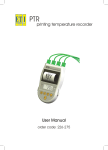
Stirred Water
calibration bath
User Manual
order code 822-900
2
CONTENTS
introduction4
safety & assembly
5
operation6
set point temperature
6
calibration6
detailed operation of the controller
6
offset function
6
integral function
7
warranty7
specification 8
3
INTRODUCTION
The stirred water bath provides a simple and accurate method of checking
the accuracy of thermometer sensors. These units are ideal for use in
a variety of industrial and process applications, checking probes or
temperature data loggers. For further confidence in calibration, each unit
can be issued with a traceable Certificate of Calibration showing actual
test data, which can be used as part of a quality assurance programme.
For improved accuracy of calibration, a Reference thermometer with a
UKAS Certificate of Calibration can be used in conjunction with the bath.
For details of ETI Reference thermometers, please contact the ETI Sales
team on 01903 202151 or [email protected].
4
SAFETY & ASSEMBLY
The Calibration Bath should only be operated by a person who has
thoroughly read and understood this manual.
The Bath consists of three main parts:- base, lid and heater unit.
When assembling the bath, the heater unit must be placed to the left-hand
side. The vents from the heater unit must be towards the outside.
The bath MUST contain sufficient water to cover the stirrer and heater coil
by at least 30 mm.
Do not remove the heater unit from the bath with the power lead still
connected to a power source.
The heater coil can operate to a very high temperature. Precautions
MUST be taken to prevent personal injury or damage to surrounding
objects. The unit will remain hot for several minutes after switching off.
Allow to cool before storage.
This calibration bath is designed to be rugged and durable but does contain
electronics that must be protected from splashing of water.
Connect input power lead to only a 230 volt, 50-60 Hz grounded AC
power supply.
Mains plug fuse rating to be 13 Amp.
ETI calibration baths are programmed and calibrated at the factory
for optimum performance and should not need adjusting. The
heater unit is equipped with a circuit breaker electrical fuse. If the fuse
blows, allow the unit to cool before pressing the reset button. If the fuse
will not reset, return to the supplier for inspection and repair. Note: there
are no user serviceable parts inside.
!
!
5
OPERATION
IMPORTANT: Do not turn on the heater unit unless there is sufficient
water in the bath. i.e. at least 30 mm of cover to the heater and stirrer.
SET POINT TEMPERATURE
To set the required temperature push the centre 'up' button, or right 'down'
button as required.
After the temperature has been set, the display will return to indicate the
temperature of the water in the bath.
Leave the bath for 20 minutes until the display has stabilised.
If the water temperature is not as the set point, adjust the offset using the
'left' button.
See 'Detailed operation of the controller' for more information.
CALIBRATION
It is recommended that a Reference thermometer be used in conjunction
with the bath to enhance the accuracy of the calibration procedure.
DETAILED OPERATION OF THE CONTROLLER
SET POINT TEMPERATURE
Pushing the centre 'up' button, or right 'down' button as required sets the
required temperature. After the temperature has been set, the display will
return to indicate the temperature of the water in the bath.
As the thermal mass of the water bath is large, it is preferable to minimise
any overshoot in temperature as the time taken to return to the set point is
dependent on the temperature of the bath and the ambient temperature.
To avoid temperature overshoot the unit is initially configured as a
proportional only controller with a proportional band of 10 °C.
In the steady state (i.e. the water temperature has become stable) the
indicated temperature may be lower than the required set point. In this
case the offset function will need to be set to reduce the difference.
OFFSET FUNCTION
Press the left-hand button for five seconds and the display will indicate
'A2 dy', press the left-hand button again to display 'SHif'. Adjustment of
the 'up' or 'down' buttons will now adjust the offset value.
6
Offset is measured in % with range 0-100 % of the 10 °C proportional
band. Therefore 1 % will correct for a difference of 0.1 °C. Small 0.5 %
changes will avoid any overshoot.
An alternative configuration to the above is proportional plus integral
action, this will avoid the need to keep manually correcting for any set
point difference and will shorten the time taken to reach set point. However
there will be an overshoot in temperature.
INTEGRAL FUNCTION
Press the left-hand button three times and the display will indicate 'ti 1',
adjustment of the 'up' and 'down' buttons will adjust the integral value.
Integral time is measured in seconds with range 0-1000 seconds.
Zero seconds means that the integral is off. Note: setting the integral will
inhibit the offset function.
The shorter the integral time the faster the set point is achieved, but the
larger the overshoot.
At 70 °C a 50 second integral time will give reasonable response time
with a short settling time.
All settings are retained when the unit is turned off so once set, further
adjustment should not be required.
WARRANTY
This instrument carries a twelve-month warranty and guarantee against
defects in either components or workmanship. During this period, products
that prove to be defective, will, at the discretion of ETI, be either repaired
or replaced without charge.
The product warranty and guarantee does not cover damage caused by
fair wear and tear, abnormal storage conditions, incorrect use, accidental
misuse, abuse, neglect, misapplication or modification, or use with nonETI hardware/software. No warranty of fitness for a particular purpose
is offered and the user assumes the entire risk of using the product. Any
liability by ETI is limited only to the replacement of defective materials or
workmanship, and ETI accepts no responsibility for consequential loss.
In line with our policy of continuous development, we reserve the right to
amend our product specification without prior notice.
7
SPECIFICATION
range
resolution
accuracy
stability
heating time
power
dimensions
weight
ambient to 100 °C (above 70 °C use oil)
0.1 °C
±0.5 °C
±0.5 °C
ambient to 60 °C takes 30 minutes
230 volt AC (115 volt available)
180 x 260 x 315 mm
7500 grams
supplied by
Electronic Temperature Instruments Ltd
Easting Close, Worthing, West Sussex BN14 8HQ
tel: 01903 202151 · fax: 01903 202445
e-mail: [email protected] · www.etiltd.com
8
18.2.11