1
SMAC
The ability to do work and verify its accuracy
SMAC
LAD-1
Technical Reference Manual
SMAC 5807 Van Allen Way Carlsbad California 92008 USA
SMAC Europe Limited Tel 01403 276488 Fax 01403 256266
S.M.A.C.
5807 VAN ALLEN WAY
CARLSBAD, CA 92008
PHONE: 1-760-929-7575 / FAX: 1-760-929-7588
FOR TECHNICAL ASSISTANCE CALL: 1-760-929-7575
© COPYRIGHT AUTOMATION MODULES, INC. 2002
SMAC
LAD-1 Technical Reference Manual
1. INTRODUCTION...................................................................................................................................... 4
1.1 SPECIFICATIONS ....................................................................................................................................... 4
1.2 DEDICATED DIGITAL INPUTS ...................................................................................................................... 5
1.2.1 Command Pulse Inputs................................................................................................................ 5
1.2.2 Additional Inputs .......................................................................................................................... 5
1.2.3 Dedicated Digital Outputs............................................................................................................ 6
1.3 INCREMENTAL ENCODER INTERFACE ......................................................................................................... 7
1.4 OUTPUT DRIVER INTERFACE ..................................................................................................................... 7
1.5 RS-232 SERIAL INTERFACE...................................................................................................................... 7
2. MODES OF OPERATION ....................................................................................................................... 8
2.1
2.2
2.3
2.4
POSITION MODE ....................................................................................................................................... 8
TORQUE MODE ........................................................................................................................................ 8
SWITCHING MODES .................................................................................................................................. 8
OUTPUT LIMITING ..................................................................................................................................... 9
3. ENTERING COMMANDS...................................................................................................................... 10
3.1 DOWNLOADING COMMANDS .................................................................................................................... 11
3.2 COMMANDS............................................................................................................................................ 11
4. APPENDIX A, LAD-1 ERROR CODE DEFINITIONS........................................................................... 18
5. APPENDIX B, SUMMARY OF LAD-1 COMMANDS............................................................................. 19
6. APPENDIX C, LAD-1 CONNECTOR PIN DEFINITIONS
3
................................................................ 20
SMAC
LAD-1 Technical Reference Manual
1. Introduction
The LAD-1 is a device capable of allowing a motion controller with only step and direction (or
count up / count down) type signals to control a brush-type DC servomotor or voice coil actuator thereby
allowing those to be used in applications formerly assigned to stepping motors.
The LAD-1 implements a mnemonic type command instruction set via a standard RS-232 serial
communications interface. These commands are used to set various operating parameters which are
then stored in non-volatile memory for automatic retrieval at power-up.
The LAD-1 interfaces to the real world via an onboard PWM DC motor driver, a quadrature type
encoder interface, 8 dedicated optoisolated digital inputs and 4 dedicated optoisolated digital outputs and
an RS-232 serial communications link.
1.1 Specifications
Description
Operating Modes
Filter Algorithm
Servo Loop Rate
Servo Position Feedback
Output
PWM Frequency
Encoder Input
Encoder Output
Encoder Supply Voltage
Encoder Input Voltage
Encoder Count Rate
Command Pulse Count
Rate
Dedicated Digital Inputs
Dedicated Digital Outputs
Communication Interface
Supply Voltage
Motor Voltage
Dimensions
Weight
Stand-Alone 1 Axis Servo Motor Indexer / Driver
Position, Torque
PID
10 KHz
Incremental Quadrature Encoder
PWM Motor Drive, 3 Amps Cont. and 6 Amps Peak at 48 VDC Max.
Approximately 19.531 KHz
Single-ended or Differential
Differential
5 VDC
5.5 VDC Max., -0.1 VDC Min.
2 Million Quadrature Counts per Second
1 Million Quadrature Counts per Second (count and/or direction state
must remain unchanged for 500 nS minimum)
Reset, Clear, Output_Limit, Mode (x3), Count Up / Step (+5VDC
only), Count Down / Direction (+5VDC only), all optoisolated.
Ready, Over-Temp, Overflow, In_Position, all optoisolated.
RS-232 Serial Interface, 9600 Baud, 8 Bits, 1 Stop Bit, No Parity,
XON / XOFF Handshake
+11 To +48 VDC
+12 To +48 VDC
Approximately 4.1” Long by 4.0” Wide by 1.1” Thick
Approximately 10 oz.
Table 1. Specifications.
4
SMAC
LAD-1 Technical Reference Manual
1.2 Dedicated Digital Inputs
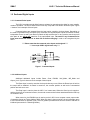
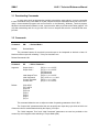
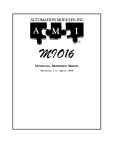
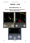
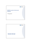
1.2.1 Command Pulse Inputs
The LAD-1 provides several digital inputs to enhance its operation and to allow for more versatile
modes of operation. The first of these are the Count Up / Step and Count Down / Direction inputs. Figure
1 shows a circuit example of these inputs.
Command pulses are accepted from the host motion controller via these inputs. Depending on
the mode of operation set by the Phase (PH) command, the command pulse inputs will function as either
independent Count Up and Count Down or paired as Step and Direction. In any case the actual count will
take place at the “on to off” transition of the optoisolated input. The state of any Command Pulse
input must remain the same for at least 500 ns before changing in order to be recognized by the
LAD-1.
! ! ! Please note that the command pulse inputs are designed ! ! !
! ! ! to accept +5VDC signal levels only. ! ! !
Figure 1. Command Inputs
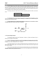
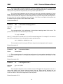
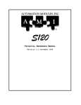
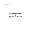
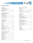
1.2.2 Additional Inputs
Additional dedicated inputs include Reset, Clear, PM/QM, InitC_Mode, INP_Mode and
Output_Limit. Figure 2 shows a circuit example of these inputs.
The Reset input is used to reset the device and clear any errors. When the Reset input is held on
the output will be disabled. As Reset is turned off, the encoder position as well as the commanded
position are both set to zero.
The Clear input is used to place the LAD-1 in a known state. When the Clear input is turned on
and then back off, the command counter, the encoder counter and all values associated with the PID loop
are cleared to zero.
When turned on, the PM/QM input is used to put the LAD-1 into a constant current output mode
of operation (known as Torque Mode or QM). When this input is then turned off, the unit will again return
to the Position Mode of operation (PM). The InitC_Mode input determines how the switch to QM will be
initialized (see section 2.4 Switching Modes).
5
SMAC
LAD-1 Technical Reference Manual
The INP_Mode input is used to control the function of the In_Position output. When this input is
turned off, the In_Position output will be turned on when the position following error (the TF command) is
less than or equal to the value set by the Set Error (SE) command. When the INP_Mode input is turned
on, the In_Position output will then be turned on when the output current value exceeds the value set by
system parameter Current Threshold (see PI and DP commands).
levels:
The Output_Limit input is used to limit the maximum output duty cycle of the LAD-1 to one of two
Output_Limit
Off
On
Use Output Limit 0
Use Output Limit 1
The Parameter Index (PI) and Define Parameter (DP) commands are used together to set the
values for these different levels (see PI and DP commands). The default values for these settings are
100% duty cycle and 75% duty cycle.
The logic state on any of these inputs should be maintained for at least 200 us before
changing to guarantee that the input state is recognized.
Figure 2. Other Inputs
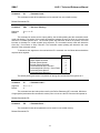
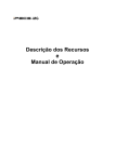
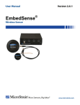
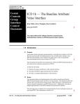
1.2.3 Dedicated Digital Outputs
The dedicated outputs include Over-Temperature, Overflow, In_Position and Ready. Figure 3
shows a circuit example of these outputs.
The Over-Temperature output will turn on when the temperature of the power driver of the LAD-1
exceeds 140° C. In this case the output of the LAD-1 will go inactive and will remain that way until the
temperature of the driver falls below the 140° C threshold.
The Overflow signal will turn on when the deviation between the commanded input pulse count
and the servo motor encoder pulse count exceeds ±2047 counts. When this occurs the output of the
LAD-1 will be disabled.
The In_Position output will be turned on when the deviation between the commanded input pulse
count and the servo motor encoder pulse count is less then the value programmed by the Set Error (SE)
command. Otherwise this output will be turned off.
6
SMAC
LAD-1 Technical Reference Manual
The Ready output is turned on when the LAD-1 is capable of normal operation. In the event of an
Over-Temperature or Overflow condition, the Ready output will be turned off. Turning the Reset input on
will also cause the Ready output to turn off.
Figure 3. Dedicated Output
1.3 Incremental Encoder Interface
The LAD-1 has a quadrature type encoder interface and the ability to supply +5 VDC at a
minimum of 50 mA. The phase A+, phase B+, and Index+ inputs are pulled up to +5 VDC with 2.7K
resistors. The phase A- , phase B- and Index- inputs are biased at +2.5 VDC with 2.7K resistors. This
arrangement will accommodate both open collector and totem pole single-ended output encoders or line
driver output encoders. The phasing of the channels (as interpreted by the LAD-1) can be changed via
program command.
The encoder signals are received by a 2632 type line receiver. These signals are then passed
through the LAD-1 to a 2631 type line driver for optional use by the hosting motion controller. The
phasing command will have no effect on these signals.
1.4 Output Driver Interface
The LAD-1 onboard output driver is a PWM switching amplifier capable of supplying 3 Amps
continuous and 6 Amps peak (for 200 mS minimum) at a switching frequency of approximately 19.531
KHz. This driver is intended for driving DC brush type motors or voice coil actuators. The driver uses the
main power supply input and the peak voltage output to the motor will be nearly that of what is supplied.
The output phasing of the driver can be changed via the Phase (PH) command.
The output driver includes an over-temperature sensor. If this sensor determines that the driver
temperature is greater than 140° C, the driver will then be disabled, the Over-Temperature output will be
turned on and the Ready output will be turned off.
1.5 RS-232 Serial Interface
The LAD-1 communicates with a host computer or a "dumb" terminal via an RS-232 serial
interface. The baud rate is fixed at 9600 baud. Characters are fixed at 8 bits in length with 1 stop bit and
no parity. Software XON / XOFF handshaking is supported. Hardware handshaking is not supported.
7
SMAC
LAD-1 Technical Reference Manual
2. Modes of Operation
2.1 Position Mode
In normal operation, the LAD-1 will accept command pulses from the host motion controller. For
each command pulse, the commanded position of the servo motor is either incremented or decremented.
The LAD-1 does no trajectory planning as the frequency and rate of change of command pulses will
ultimately determine the velocity profile. Unlike a normal open-loop stepping motor, if command pulses
are given at a rate faster than the servomotor can respond, the LAD-1 will not lose count. The motor will
simply lag behind until it is able to catch up.
2.2 Torque Mode
The LAD-1 is capable of operating in a constant current output mode known as Torque Mode.
When Torque mode is entered the LAD-1 will no longer operate in a position holding mode. Instead it will
operate in a constant current output mode with the commanded current being set by the command pulses
from the motion controller.
The maximum usable range of commanded current is from 0 to ±1023 counts representing from
0 to ±5 Amps of output current (although the count is tracked to a command of up to ±32767 counts to
prevent overflows). As with any current source, the actual achievable output current will depend upon the
load impedance and power supply voltage.
2.3 Switching Modes
When the PM/QM input is turned on, the LAD-1 will switch from Position mode (PM) to Torque
mode (QM) of operation. When this occurs, the LAD-1 assumes an initial command of zero. Also,
because the constant current loop error integrator is unknown it is set to zero.
This can present a problem in some applications in the form of a time lag in the output while the
command is stepped to its required level and the error integrator ramps up sufficiently to create the
necessary output. In order to reduce this output lag time in applications that require it, two system
parameters are available to the user: “Initial Integral Term” (PI4) and “Initial Command” (PI5).
When the LAD-1 switches to QM, instead of assuming an initial output of zero, the command
counter is loaded with the “Initial Command” (Init_C) parameter. This allows the user to preset an output
when switching modes. In a like manner, the error integrator is loaded with the “Initial Integrator Term”
(Init_I) parameter. This value is previously arrived at through empirical testing.
The InitC_Mode input allows a further degree of flexibility by substituting the measured value of
the actual output current for the Init_C parameter when the unit enters QM. This allows the unit to
automatically keep suppling the same output force when switching from PM to QM.
Because the command counter is used differently in Torque mode, when switching back to
position mode by turning off the PM/QM input, the LAD-1 will have lost its command reference.
Therefore, the command counter is loaded with the current value of the encoder counter and all PID loop
8
SMAC
LAD-1 Technical Reference Manual
related variables are reset (i.e. following error, derivative term, etc.). The motor / actuator will need to be
homed after operating in Torque mode.
2.4 Output Limiting
By using the Output_Limit input, the maximum output duty cycle of the LAD-1 can be set to one
of two different levels. The value for the two levels is set by using the Parameter Index (PI) and Define
Parameter (DP) commands. The proper method for doing this is to first use the PI command to set the
parameter index pointed to the desired system parameter, then to use the DP command to set the new
value. For example:
PI0,DP32767
PI1,DP24576
; OL Input = 0 - max DC = 100%
; OL Input = 1 - max DC = 75%
9
SMAC
LAD-1 Technical Reference Manual
3. Entering Commands
Immediately after power-up, the LAD-1 is ready to accept commands. To verify this, you can hit
the ESC key. If everything is working properly, this should cause a greater than sign (">") prompt to
appear on your display. If not, you need to verify that the power and communications connections are
correct and verify the compatibility of the communications protocol.
Commands are entered via a "dumb" terminal or host computer such as a PC compatible.
Commands sent to the LAD-1 should consist of standard ASCII characters, and the command lines
should be followed by a carriage return. Linefeeds are not necessary since they are used for formatting
and therefore they are ignored. As characters are entered at the keyboard, they should be echoed on
your display. If your display echoes its own transmitted characters, you will want to issue the Echo Off
(EF) command; otherwise, the Echo On (EN) command (which is the default mode) should be issued. If
you enter an invalid command, the LAD-1 will respond with a question mark "?" followed by a code
indicating the type of error. These codes are listed on page 18 in the appendix.
If you make a mistake when entering a command, you can backspace to correct the error. If you
are entering commands and change your mind, hitting the ESC key will cancel the line and give a new ">"
prompt.
Once a command line has been entered and has finished executing, hitting the RETURN key
will cause the same command line to be re-executed.
Command instructions are intended for use with the following syntax:
Command[Argument]<CR>
or...
Command[Argument],Command[Argument],...etc.
The numerical range of an argument will vary depending on the command with which it is used.
The mathematical interpretation of the argument will depend on whether the Decimal Mode (DM) or
Hexadecimal Mode (HM) was the last issued (DM is the power on default). Both decimal and
hexadecimal numbers less than zero should be entered with a preceding minus "-" sign. If no argument is
given, then it will be assumed as "0". It should be noted that commands can be strung together by using
commas, up to a maximum line length of 127 characters.
If a command line contains the semicolon character ";", i.e...
>SG1000,SD5000 ; Set filter gains.<CR>
then the ";" and anything following it to the end of the line will be ignored. This feature is not particularly
useful if you are entering commands manually, as comments are not retained by the LAD-1. However, if
commands are downloaded to the LAD-1 from a host computer, the ability for line comments can make
setup documentation possible and desirable.
10
SMAC
LAD-1 Technical Reference Manual
3.1 Downloading Commands
In many cases (such as programming multiple units with the same values), it is more convenient
to enter commands using a text editor on a host computer and then download that text file to the LAD-1
using a communications program such as ProComm or the Microsoft Windows Terminal program.
Whatever communications software is used, it must have the ability to provide a short delay (approx. 100
mS) after transmitting each line to give the LAD-1 time to interpret and store the commands that were
just sent.
3.2 Commands
Command:
DM
-- Decimal Mode --
Default:
Decimal Mode
This command causes all numerical input and output to be interpreted as decimal or base 10.
Numbers will be output with a leading "-" if they are less than zero.
Related Commands: HM
Command:
DP
-- Define Parameter --
Argument:
Output Limit 0
Output Limit 1
Initial Integral Term
Initial Command
Current Threshold
Current Gain
Default:
(PI0) 0 <= n <= 32767
(PI1) 0 <= n <= 32767
(PI2) Reserved
(PI3) Reserved
(PI4) 0 <= n <= 32767
(PI5) -1023 <= n <= 1023
(PI6) 0 <= n <= 1023
(PI7) 0 <= n <= 32767
(PI0) 32767
(PI1) 24576
(PI2) n/a
(PI3) n/a
(PI4) 0
(PI5) 0
(PI6) 0
(PI7) 0
This command allows the user to adjust a number of operating parameters of the LAD-1.
The “Output Limit” parameters allow the user to specify two output duty cycle limits of which one
of these at a time is used as determined by the Output_Limit input.
The “Initial Integrator Term” and “Initial Command” parameters are used as pre-loads to the
current loop error integrator when switching to Torque Mode (QM).
11
SMAC
LAD-1 Technical Reference Manual
The “Current Gain Threshold” parameter is used a comparator value for the In_Position signal
when the INP_Mode input is turned on. When the output current (as reported by the TC command) is at a
value equal to or greater than this parameter, the In_Position output will turn on.
The “Current Gain” parameter sets the current loop error gain used when operating in Torque
Mode. This allows the response of the current error integrator to be adjusted to suit different applications.
A low value will provide slow response to load changes while a high value will provide quick response. If
the value is set too low then inadequate control may occur. If the value is too high then the system may
be unstable. A good "general" value is about 5000 to 8000.
Related Commands: PI
Command:
FRn
-- Set Derivative Sampling Period --
Argument:
Default:
0 <= n <= 127
0
This command allows for the adjustment of the derivative sampling interval for the servo. The
period of this interval can be calculated by the following:
T = (n+1) * 0.000100
where "T" is the period in seconds and "n" is the FR command argument. For example, if the value set
by the FR command were 9, then the derivative sample period would be:
(9+1) * 0.000100 = .001000 S or 1 mS
This command is useful in tuning the PID servo loop to the inertial properties of the system.
Related Commands: RI
Command:
HM
-- Hexadecimal Mode --
Default:
Decimal Mode
This command causes all numerical input and output to be interpreted as hexadecimal or base
16. Numbers will be output as 2, 4 or 8 digits with leading 0's if they are positive and leading F's if they
are negative.
Related Commands: DM
Command:
ILn
-- Set Integration Limit --
Argument:
Default:
0 <= n <= 16,383
0
This command clamps the level of influence that the PID digital filter integral term can use to
reduce static position error thereby reducing integral “wind up”. When properly adjusted, this can
enhance loop stability and operation. The Integral Limit (IL) and Set Integral Gain (SI) must both be set to
a non-zero value in order for the integral term to have any effect.
Related Commands: RI, SI
12
SMAC
LAD-1 Technical Reference Manual
Command:
PL
-- Parameter Load --
This command causes all set parameters to be restored from non-volatile memory.
Related Commands: PS
Command:
PHn
-- Set Servo Phasing --
Argument:
Default:
0 <= n <= 15
0
This command is used to set the output polarity, the encoder phasing and the command counter
mode and phasing. The polarity of the output will determine whether the servo is driven in a direction that
reduces or increases position error. The encoder phase will determine whether the position count will
increase or decrease for a valid encoder input sequence. The command counter mode will determine
Count Up / Count Down or Step / Direction. The command counter phasing will determine the count
direction of the command counter.
To determine the argument to be used with the PH command, use the follow table and add the
required values together.
Output Phase Normal
Output Phase Reversed
Encoder Phase Normal
Encoder Phase Reversed
Command Mode Step / Direction
Command Mode Count Up / Count Down
Command Phase Normal
Command Phase Reversed
Add to 'n'
0
1
0
2
0
4
0
8
The default phasing and sense is equivalent to issuing this command with a argument of 0.
Command:
PI
-- Parameter Index --
Argument:
Default:
0 <= n <= 7
0
This command sets the index pointer used by the Define Parameter (DP) command. Whichever
of eight special parameters this command is used to point to is the one the DP command will operate on.
Related Commands: DP
Command:
PS
-- Parameter Store --
This command causes all set parameters to be saved in non-volatile memory.
Related Commands: PL
13
SMAC
LAD-1 Technical Reference Manual
Command:
RIn
-- Sampling Rate of Integral --
Argument:
Default:
0 <= n <= 127
0
This command allows for the adjustment of the PID digital filter integral sampling interval for the
servo. The period of this interval can be calculated by the following:
T = (n+1) * 0.000100
where "T" is the period in seconds and "n" is the RI command argument. For example, if the value set by
the RI command is 1, then the integral sample period will be:
(1+1) * 0.000100 = .000200 S or 200 uS
This command is useful in tuning the PID servo loop to the inertial properties of the system.
Related Commands: FR
Command:
SDn
-- Set Derivative Gain --
Argument:
Default:
0 <= n <= 32,767
0
This command sets the derivative gain term of the PID digital filter loop for the servo.
Related Commands: SG, SI, IL
Command:
SEn
-- Set Maximum Following Error --
Argument:
Default:
0 <= n <= 16,383
16,383
This command is used to set the maximum deviation of the encoder position from the
commanded position for the servo that will allow activation of the In_Position output signal. If the deviation
exceeds the programmed value, the In_Position output will be turned off.
Related Commands: TF
Command:
SGn
-- Set Proportional Gain --
Argument:
Default:
0 <= n <= 32,767
0
This command sets the proportional gain term of the PID digital filter loop for the servo.
Related Commands: SI, SD, IL
14
SMAC
LAD-1 Technical Reference Manual
Command:
SIn
-- Set Integral Gain --
Argument:
Default:
0 <= n <= 32,767
0
This command sets the integral gain term of the PID digital filter loop for the servo. The Set
Integral Gain (SI) and Integral Limit (IL) must both be set to a non-zero value in order for the integral term
to have any effect.
Related Commands: SG, SD, IL
Command:
TC
-- Tell Current Output --
This command reports the output current that is flowing through the load. The value will be from 0
to 1023 representing a current of from 0 to 5 amps.
Command:
TD
-- Tell Derivative Gain --
This command reports the derivative gain value of the PID digital filter for the servo.
Related Commands: TG, TI, TL
Command:
TF
-- Tell Following Error --
This command reports the following error for the servo. This value is the difference between the
current command count position (or that which is reported by the Tell Optimal (TO) command) and the
servo's current real position (or that which is reported by the Tell Position (TP) command).
Related Commands: SE
Command:
TG
-- Tell Proportional Gain --
This command reports the proportional gain value of the PID digital filter for the servo.
Related Commands: TI, TD, TL
Command:
TI
-- Tell Integral Gain --
This command reports the integral gain value of the PID digital filter for the servo.
Related Commands: TG, TD, IL
15
SMAC
LAD-1 Technical Reference Manual
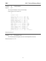
Command:
TK
Argument:
none
-- Tell (K) Constants --
This command will display a number of internal settings.
Example display for the command "TK":
>TK
Parameter Values...
Proportional Gain ---------- (SG)
Integral Gain -------------- (SI)
Derivative Gain ------------ (SD)
Integral Limit ------------- (IL)
Maximum Following Error ---- (SE)
Integral Sample Rate ------- (RI)
Derivative Sample Rate ----- (FR)
Phase and Sense Settings --- (PH)
Output Limit 0 --------- (PI0,DP)
Output Limit 1 --------- (PI1,DP)
Output Limit 2 --------- (PI2,DP)
Output Limit 3 --------- (PI3,DP)
Initial Integral Term -- (PI4,DP)
Initial Command -------- (PI5,DP)
Current Threshold ------ (PI6,DP)
Current Gain ----------- (PI7,DP)
Firmware Revision ---------- (VE)
>
=
=
=
=
=
=
=
=
=
=
=
=
=
=
=
=
=
300
200
5000
10000
2
0
2
0
32767
24576
16384
8192
0
0
0
5000
1.03 Mod516
Related Commands: VE
Command:
TL
-- Tell Integration Limit --
This command reports the integration limit value of the PID digital filter for the servo.
Related Commands: TG, TI, TD
16
SMAC
LAD-1 Technical Reference Manual
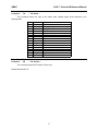
Command:
TS
-- Tell Status --
This command reports the value of the status word variable whose bit are defined by the
following table:
Bit
0
1
2
3
4
5
6
7
8
9
10
11
12
13
14
15
Command:
VE
Name
Reserved
OLmt0_B
Mode2
Mode0
Mode1
OMode0
Reserved
Reserved
Enabled
NewReset
OldReset
NewClr
OldClr
Reserved
HexMod
Blink
Purpose
Reserved
Output_Limit input 0 state, 1 = “on”
InitC_Mode input state, 1 = “on”
PM/QM mode input state, 1 = “on”
INP_Mode input state, 1 = “on”
Old INP_Mode input state, 1 = “on”
Reserved
Reserved
Output enabled state, 1 = “enabled”
Reset input state, 1 = “on”
Old reset input state, 1 = “on”
Clear input state, 1 = “on”
Old clear input state, 1 = “on”
Reserved
1 = Hex output mode
LED blink state
-- Tell Version --
This command reports the firmware revision level.
Related Commands: TK
17
SMAC
LAD-1 Technical Reference Manual
4. Appendix A, LAD-1 Error Code Definitions
1 - ARGUMENT ERROR.
This error indicates that a command argument was not given or was specified out of the
permissible numerical range.
2 - INVALID COMMAND.
This error indicates that an invalid or unrecognized command was specified in the command line.
18
SMAC
LAD-1 Technical Reference Manual
5. Appendix B, Summary of LAD-1 Commands
DM -DP -FR -HM -IL -PH -PI -PL -PS -RI -RT -SD -SE -SG -SI -TC -TD -TF -TG -TI -TK -TL -TO -TP -TQ -TS -VE -ZZ --
Decimal Mode
Define Parameter
Derivative Sampling Frequency
Hexadecimal Mode
Integration Limit
Phase
Parameter Index
Parameter Load
Parameter Store
Sampling Rate of Integral
Reset
Set Derivative Gain
Set Error
Set Proportional Gain
Set Integral Gain
Tell Current
Tell Derivative Gain
Tell Following Error
Tell Position Gain
Tell Integral Gain
Tell (K)Constants
Tell Integration Limit
Tell Optimal Position
Tell Real Position
Tell Torque
Tell Status
Tell Version
Dump Memory
19
SMAC
LAD-1 Technical Reference Manual
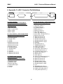
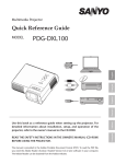
6. Appendix C, LAD-1 Connector Pin Definitions
POWER INTERFACE
SERVO INTERFACE
RS-232
USER I/O
1
1
1
1
J1 - Power Interface :
4-Pin 5.08mm Centers Terminal Block
Mating Connector: OnShore# EDZ95004
Digi-Key# ED1719
J6 - User I/O Interface : 37-Pin Female D-Sub
Mating Connector: Digi-Key# 237M
1. Over-temp. output (+)
2. Overflow output (+)
3. In_Position output (+)
4. Ready output (+)
5. Reset input return (-)
6. Clear input return (-)
7. Count_Up / Step input (+)
8. Count_Down / Dir input return (-)
9. Reserved, do not use
10. Reserved, do not use
11. Reserved, do not use
12. Encoder Index- output
13. Encoder phase B+ output
14. Encoder phase A+ output
15. Common
16. INP_Mode input (+)
17. PM/QM Mode input (+)
18. Output_Limit input (+)
19. InitC_Mode input (+)
20. Over-temp. output return (-)
21. Overflow output return (-)
22. In_Position output return (-)
23. Ready output return (-)
24. Reset input (+)
25. Clear input (+)
26. Count_Up / Step input return (-)
27. Count_Down / Dir input (+)
28. Reserved, do not use
29. Reserved, do not use
30. Encoder Index+ output
31. Encoder phase B- output
32. Encoder phase A- output
33. +5V
34. INP_Mode input return (-)
35. PM/QM Mode input return (-)
36. Output_Limit input return (-)
37. InitC_Mode input return (-)
1. Main power return
2. Main V+ power input
3. Motor+ output
4. Motor- output
J2 - Servo Interface : 15-Pin Female D-Sub
Mating Connector: Digi-Key# 215M
1. Encoder phase A+
2. Encoder phase B+
3. Encoder Index+
4. +5 VDC
5. +5 VDC
6. Reserved, do not use
7. Reserved, do not use
8. Reserved, do not use
9. Encoder phase A10. Encoder phase B11. Encoder Index12. Common
13. Common
14. Reserved, do not use
15. Reserved, do not use
J5 - RS-232 Comm. Interface:
6-Pin Modular Jack
Mating Connector: Digi-Key# A9093
1. Handshake output
2. Handshake input
3. Receive data input
4. Transmit data output
5. Common
6. +5 VDC
20