1
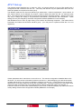
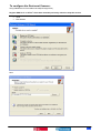
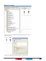
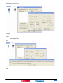
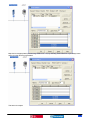
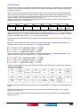
Application Note – 17
ATV71 DeviceNet implementation
example
Schneider Electric
1
Table of Contents
Table of Contents ................................................................................................................2
Application Note Overview...................................................................................................2
References ..........................................................................................................................3
PDL vs. ATV71 Implementation differences ........................................................................3
ATV71 Set-up ......................................................................................................................4
To configure the Drive- .....................................................................................................5
To configure the Devicenet Scanner- ...............................................................................8
Register EDS file ...........................................................................................................8
Adding to a project..........................................................................................................12
Conclusion .........................................................................................................................17
Application Note Overview
This note describes how to install an ATV71 onto an existing devicenet network and how
to attain similar performance to an Elite drive configured for PDL instances 100 and 101.
Key differences in devicenet implementation between the ATV 71 and PDL Elite ranges
are also described.
Should you need more information on this or other features of the drive please see a
Schneider-Electric representative.
Prerequisites: Good understanding of PLC ladder logic and RSLogix5000.
Basic understanding of an ATV71 drives control.
Written By
Name
Title
Date:
14-Jul-06
PAE Department
Approved By:
Peter Wrigley
Marc Marchal
Product Application Engineer
Application Engineering Manager
Ref:
Version:
AppNote 17
Release 01
Schneider Electric
2
References
•
ATV71 option board installation manual (1754480)
•
ATV71 Installation annual (1755849).
•
ATV71 Communications parameters user manual (1755861)
•
ATV71 Devicenet Card user manual (1755877)
•
PDL Elite Series Technical Manual (4201-180 Rev L)
•
PDL EDNI Device Interface Manual (4201-212 Rev C)
PDL vs. ATV71 Implementation differences
There are two major differences that need to be considered in relation to devicenet implementation of an
ATV71 drive versus an Elite drive. They are1. The Elite drive forced the user to select either one of the standard ODVA instances (both input and
output) or alternatively the PDL specific instances 100 and 101. The ATV71 however is not limited
to these instances and the control and speed references are completely customisable. The ATV71
devicenet card itself is configured for either the ODVA instances, Schneider specific instances or AB
specific instances but how the drive responds to these is completely flexible.
2. The PDL instances 100 and 101 allowed for multiplexing data from the Elite drives. This feature is
not supported by the ATV71. The explicit messaging function should be used to duplicate this
functionality.
Schneider Electric
3
ATV71 Set-up
The following pages describe how to setup an ATV71 to behave similarly to how an Elite would have if
configured for PDL instances 100 and 101. This setup will assume only two parameters other than the
status and speed are required to be read cyclicly.
The different instances can also have different byte transmission / receive requirements. Input instance 70
and output instance 20 for example only require 4 bytes of data each while 100 and 101 require 8 bytes
each. This requirement must be known by both the drive and the devicenet scanner. With the ATV71 the
only way to change this setting is via parameters PollProdPath, PollConsPath and CCProdPath. These
settings can only be changed by devicenet configuration software (RSNetworx in this example).
With RSNetworx this is done by right clicking on the device and selecting Properties. Then select Device
Parameters and select the Devicenet Interface group. (You may have to upload the EDS file if it is not
registered)
If these parameters don’t match then an error will occur. The scanner configuration is detailed later in this
document. For this note we would select instances 100 and 101. When designing your devicenet network
consider that the ATV71 out of the box defaults to instances 100 and 101. These instances can be used to
duplicate any of the other instances as they are completely open. If however instance 70 is used and a drive
/ devicenet card combination has to be replaced then the above settings will need to be changed. If
instances 100 and 101 have been used all settings can be done via the drive display only without the need to
modify settings via devicenet configuration software (RSNetworx for example)
Schneider Electric
4
To configure the DriveFirstly ensure the following steps have been taken-
To attain similar performance to PDL’s Output instance 100 make the following adjustments to the
drive parameters-
In Menu [1.5 INPUTS / OUTPUTS CFG] (I-O-)
Set tCC [2/3 wire control] to [2 wire] (2C): 2-wire control.
Assuming all settings listed in this note are made this configures the drive to run forward when bit 0
of the command word is high and reverse when bit 1 of the command word is high and drive digital
input five [LI5] (LI5) is not active..
Set tCt [2 wire type] to [Level] (LEL)
Assuming all settings listed in this note are made this configures the drive to run forward when bit 0
of the command word is high and reverse when bit 1 of the command word is high and drive digital
input five [LI5] (LI5) is not active..
Set rrS [Reverse assign.] to [CD301] (CD301)
Assuming all settings listed in this note are made this configures the drive to run forward when bit 0
of the command word is high and reverse when bit 1 of the command word is high and drive digital
input five [LI5] (LI5) is not active.
Schneider Electric
5
In Menu [1.6 COMMAND] (CtL-)
Set [Profile] (CHCF) to [I/O profile] (IO)
Assuming all settings listed in this note are made this configures the drive to operate in IO mode
which makes the command and reference completely customizable.
Set [Ref.1 chan] (Fr1) to [Com. card] (nEt)
Assuming all settings listed in this note are made this configures the drive speed reference to come
from the Network when drive digital input five [LI5] (LI5) is not active.
Set [Cmd channel 1] (Cd1) to [Com. card] (nEt)
Assuming all settings listed in this note are made this configures the drive to run forward when bit 0
of the command word is high and reverse when bit 1 of the command word is high and drive digital
input five [LI5] (LI5) is not active.
Set [Cmd channel 2] (Cd2) to [Terminals] (tEr)
Assuming all settings listed in this note are made this configures the drive to run forward when drive
digital input one [LI1] (LI1) is active and reverse when drive digital input two [LI2] (LI2) is active and
drive digital input five [LI5] (LI5) is active
Set [Cmd switching] to (CCS) [LI5] (LI5)
Assuming all settings listed in this note are made this configures the drive to accept run commands
from devicenet when drive digital input five [LI5] (LI5) is not active and from the terminals when it is.
In Menu [1.7 APPLICATION FUNCT.] (FUn-)
Set [Ref 1B switching] to (rCb) [LI5] (LI5)
Assuming all settings listed in this note are made this configures the drive speed reference to come
from the Network when drive digital input five [LI5] (LI5) is not active and from drive analogue input
one [AI1] (AI1) when it is.
Set [Ref.1B chan] (Fr1b) to [AI1 ref.] (AI1)
Assuming all settings listed in this note are made this configures the drive speed reference to come
from analogue input one [AI1] (AI1) when drive digital input five [LI5] (LI5) is active.
In Menu [1.8 FAULT MANAGEMENT] (FLt-)
Set rSt [FAULT RESET] to [CD302] (CD302)
Assuming all settings listed in this note are made this configures bit 2 of the command word to reset
the drive for faults that are able to be reset without cycling the drive power when drive digital input
five [LI5] (LI5) is not active. When drive digital input five [LI5] (LI5) is active drive digital input three
[LI3] (LI3) will reset the drive for faults that are able to be reset without cycling the drive power.
Schneider Electric
6
In Menu [1.9 COMMUNICATION] (COM-)
Set [Scan. Out1 address] (nCA1) to 8601
This configures the IO scanner to direct bytes 0 and 1 to address 8601 which is the drive command
word. (CMd)
Set [Scan. Out2 address] (nCA2) to 8602
This configures the IO scanner to direct bytes 2 and 3 to address 8602 which is the drive speed
reference. (LFRD)
Set [Scan. Out3 address] (nCA3) to 9001
This configures the IO scanner to direct bytes 4 and 5 to address 9001 which is the drive
acceleration rate. (ACC)
Set [Scan. Out4 address] (nCA4) to 9002
This configures the IO scanner to direct bytes 6 and 7 to address 9002 which is the drive
deceleration rate. (dEC)
[Scan. Out5 address] (nCA5) to [Scan. Out8 address] (nCA8) are not useful for the DeviceNet card.
Set [Scan. In1 address] (nMA1) to 8603
This configures the drive to direct the value held in address 8603 which is the drive status word
(EtA) to bytes 0 and 1 of the IO scanner.
Set [Scan. In2 address] (nMA2) to 8604
This configures the drive to direct the value held in address 8604 which is the drive output speed
(rFrd) to bytes 2 and 3 of the IO scanner.
Set [Scan. In3 address] (nMA3) to 9630
This configures the drive to direct the value held in address 9630 which is the motor thermal state
(tHd) to bytes 4 and 5 of the IO scanner.
Set [Scan. In4 address] (nMA4) to 3204
This configures the drive to direct the value held in address 3204 which is the motor current (LCr) to
bytes 6 and 7 of the IO scanner.
[Scan. In5 address] (nCA5) to [Scan. In8 address] (nCA8) are not useful for the DeviceNet card.
Schneider Electric
7
To configure the Devicenet ScannerUsing RSNetWorx for DeviceNet 6.00.00(build 97)(CPR 6)
Register EDS file if no ATV71’s have been installed previously otherwise skip this section.
Menu
•
•
Tools
EDS Wizard
Next
Schneider Electric
8
Select file
Ignore warnings as they are simply due to a mismatch in string length.
Change Icon to one supplied by Schneider Electric if desired.
Schneider Electric
9
Select ATV71 icon
Next
Schneider Electric
10
Next
EDS Registered
Schneider Electric
11
Adding to a project
Select the ATV71 from the vendor list and drag and drop it onto the network.
Double click on drive
Change to node address set for drive previously e.g. 12 then click OK
Schneider Electric
12
Double click on scanner
Select Module Tab
Change settings to requirements if creating a new network or alternatively skip this portion.
Interscan Delay = 20mSec
Foreground/Background Poll Ratio = 2
Select slot scanner is located in e.g = 9
Schneider Electric
13
Select Scanlist Tab
Deselect Automap on Add and add ATV71 to scan list >
Deselect Device Type, Vendor and Product code as these will cause issues when changing drives at a later
date if they have a different software version for example.
Schneider Electric
14
Select Edit I/O Parameters
Change
Polled
• Input Size 8 bytes
• Output Size 8 bytes
OK
Yes
Schneider Electric
15
Map device to appropriate Input word e.g. Node # x 2 = 24, by choosing node number X 2 you always leave
space for other devices to be added.
The same for outputs
Schneider Electric
16
Conclusion
PDL instances 100 and 101 allowed for strobing data to and from the drive. This feature is not supported by
the ATV71 drive. Explicit messaging must be used if more than four variables are required to be read from
or written to the ATV71.
When an ATV71 is configured as per this application note the drive will respond to the commands and will
derive its speed reference from the (CMd) word and (LFRD) word respectively if drive digital input five [LI5]
(LI5) is not active. When this input is active the command is taken from the terminals and the speed
reference is taken from drive analogue input one [AI1 ref.] (AI1).
Please note that a stop command from the terminals is active even when command from the network is true
(digital input five [LI5] (LI5) is not active).
The first two bytes written to the drive comprise of the (CMd) word which is configured for the followingBIT 7
BIT 6
BIT 5
BIT 4
BIT 3
BIT 2
BIT 1
BIT 0
Reset
Run
Run
Fault
Reverse
Forward
If drive digital input five [LI5] (LI5) is not active then bit 0 is a drive run forward command, bit 1 is a drive run
reverse command and bit 2 is a drive reset command. If drive digital input five [LI5] (LI5) is active then drive
digital input one [LI1] (LI1) is a drive run forward command, digital input two [LI2] (LI2) is a drive run reverse
command and digital input three [LI3] (LI3) is a drive reset command.
Bytes two and three written to the drive comprise of the speed reference (LFRD) which is an integer and the
unit is rpm.
Bytes four and five written to the drive comprise of the acceleration rate ACC [Acceleration] which is an
unsigned integer and the unit is dependent on (Inr) [Ramp increment]
Bytes six and seven written to the drive comprise of the deceleration rate dCC [Deceleration] which is an
unsigned integer and the unit is dependent on (Inr) [Ramp increment]
The first two bytes read from the drive comprise of the status word (ETA) which comprises of the following-
Bytes two and three read from the drive comprise of the output speed (rFrd) which is an integer and the unit
is rpm.
Bytes four and five read from the drive comprise of the motor thermal state (tHd) which is an unsigned
integer and the unit is 1%.
Bytes six and seven read from the drive comprise of the motor current (LCr) which is an unsigned integer
and the unit is 0.1A.
Schneider Electric
17


![[1.7 APPLICATION FUNCT.] (FUn](http://vs1.manualzilla.com/store/data/005795769_1-62115863bd572564b923fbca39341baa-150x150.png)