1
Intel® Boot Loader Development Kit
(Intel® BLDK)
Version 2.0 — UEFI Standard Based
User Guide
January 2012
Document Number: 325926-003
INFORMATION IN THIS DOCUMENT IS PROVIDED IN CONNECTION WITH INTEL PRODUCTS. NO LICENSE, EXPRESS OR IMPLIED, BY ESTOPPEL OR
OTHERWISE, TO ANY INTELLECTUAL PROPERTY RIGHTS IS GRANTED BY THIS DOCUMENT. EXCEPT AS PROVIDED IN INTEL'S TERMS AND CONDITIONS
OF SALE FOR SUCH PRODUCTS, INTEL ASSUMES NO LIABILITY WHATSOEVER AND INTEL DISCLAIMS ANY EXPRESS OR IMPLIED WARRANTY, RELATING
TO SALE AND/OR USE OF INTEL PRODUCTS INCLUDING LIABILITY OR WARRANTIES RELATING TO FITNESS FOR A PARTICULAR PURPOSE,
MERCHANTABILITY, OR INFRINGEMENT OF ANY PATENT, COPYRIGHT OR OTHER INTELLECTUAL PROPERTY RIGHT.
A "Mission Critical Application" is any application in which failure of the Intel Product could result, directly or indirectly, in personal injury or death.
SHOULD YOU PURCHASE OR USE INTEL'S PRODUCTS FOR ANY SUCH MISSION CRITICAL APPLICATION, YOU SHALL INDEMNIFY AND HOLD INTEL AND
ITS SUBSIDIARIES, SUBCONTRACTORS AND AFFILIATES, AND THE DIRECTORS, OFFICERS, AND EMPLOYEES OF EACH, HARMLESS AGAINST ALL
CLAIMS COSTS, DAMAGES, AND EXPENSES AND REASONABLE ATTORNEYS' FEES ARISING OUT OF, DIRECTLY OR INDIRECTLY, ANY CLAIM OF PRODUCT
LIABILITY, PERSONAL INJURY, OR DEATH ARISING IN ANY WAY OUT OF SUCH MISSION CRITICAL APPLICATION, WHETHER OR NOT INTEL OR ITS
SUBCONTRACTOR WAS NEGLIGENT IN THE DESIGN, MANUFACTURE, OR WARNING OF THE INTEL PRODUCT OR ANY OF ITS PARTS.
Intel may make changes to specifications and product descriptions at any time, without notice. Designers must not rely on the absence or characteristics
of any features or instructions marked "reserved" or "undefined". Intel reserves these for future definition and shall have no responsibility whatsoever
for conflicts or incompatibilities arising from future changes to them. The information here is subject to change without notice. Do not finalize a design
with this information.
The products described in this document may contain design defects or errors known as errata which may cause the product to deviate from published
specifications. Current characterized errata are available on request.
Contact your local Intel sales office or your distributor to obtain the latest specifications and before placing your product order.
Copies of documents which have an order number and are referenced in this document, or other Intel literature, may be obtained by calling 1-800-5484725, or go to: http://www.intel.com/design/literature.htm
Any software source code reprinted in this document is furnished for informational purposes only and may only be used or copied and no license, express
or implied, by estoppel or otherwise, to any of the reprinted source code is granted by this document.
Intel processor numbers are not a measure of performance. Processor numbers differentiate features within each processor family, not across different
processor families. Go to: http://www.intel.com/products/processor%5Fnumber/
Code Names are only for use by Intel to identify products, platforms, programs, services, etc. (“products”) in development by Intel that have not been
made commercially available to the public, i.e., announced, launched or shipped. They are never to be used as “commercial” names for products. Also,
they are not intended to function as trademarks.
BlueMoon, BunnyPeople, Celeron, Celeron Inside, Centrino, Centrino Inside, Cilk, Core Inside, E-GOLD, i960, Intel, the Intel logo, Intel AppUp, Intel
Atom, Intel Atom Inside, Intel Core, Intel Inside, Intel Insider, the Intel Inside logo, Intel NetBurst, Intel NetMerge, Intel NetStructure, Intel
SingleDriver, Intel SpeedStep, Intel Sponsors of Tomorrow., the Intel Sponsors of Tomorrow. logo, Intel StrataFlash, Intel vPro, Intel XScale, InTru, the
InTru logo, the InTru Inside logo, InTru soundmark, Itanium, Itanium Inside, MCS, MMX, Moblin, Pentium, Pentium Inside, Puma, skoool, the skoool logo,
SMARTi, Sound Mark, The Creators Project, The Journey Inside, Thunderbolt, Ultrabook, vPro Inside, VTune, Xeon, Xeon Inside, X-GOLD, XMM, X-PMU
and XPOSYS are trademarks of Intel Corporation in the U.S. and/or other countries.
*Other names and brands may be claimed as the property of others.
Copyright © 2012, Intel Corporation. All rights reserved.
Intel® Boot Loader Development Kit
Version 2.0 — UEFI Standard Based User Guide
2
January 2012
Document Number: 325926-003
Contents—Intel® BLDK
Contents
1.0
About This Manual ..................................................................................................... 5
1.1
Audience ............................................................................................................ 5
1.2
Related Documents and Tools ............................................................................... 5
1.3
Notational Conventions and Terminology ................................................................ 7
2.0
Product Overview ...................................................................................................... 9
2.1
Introduction to the Intel® BLDK ............................................................................ 9
2.2
Different Components of the Intel® BLDK ............................................................... 9
3.0
Intel® BLDK and Intel® UDK2010 ............................................................................ 11
3.1
Open Source Availability..................................................................................... 11
3.2
Intel® BLDK Features ........................................................................................ 11
4.0
Architecture ............................................................................................................ 13
4.1
Platform Initialization Sequences ......................................................................... 13
4.1.1 Security (SEC) Phase .............................................................................. 13
4.1.2 Pre-EFI Initialization (PEI) Phase .............................................................. 14
4.1.3 Driver Execution Environment (DXE) Phase................................................ 14
4.1.4 Boot Device Select (BDS) Phase ............................................................... 14
4.2
Boot Process..................................................................................................... 14
4.3
Types of Intel® BLDK Files.................................................................................. 15
4.4
Protocol and Drivers .......................................................................................... 16
4.5
UEFI Services ................................................................................................... 17
5.0
Intel® BLDK BSF - Introduction ............................................................................... 20
6.0
Debugging ............................................................................................................... 21
6.1
Software Debugging with the Intel® UEFI Development Kit Debugger Tool ................ 21
6.1.1 Software Debugging on Windows* ............................................................ 21
6.1.1.1 Host Machine Setup ................................................................. 22
6.1.1.2 Target Machine Setup ............................................................... 23
6.1.1.3 Starting a Debug Session .......................................................... 23
6.1.1.4 Using the Software Debugger .................................................... 23
6.1.2 Software Debugging on Linux*................................................................. 27
6.1.2.1 Host Machine Setup .................................................................. 28
6.1.2.2 Target Machine Setup................................................................ 29
6.1.2.3 Starting a Debug Session ........................................................... 29
6.1.2.4 Using the Software Debugger ..................................................... 31
6.2
Platform Level Debugging using JTAG/ITP............................................................. 35
7.0
OS Bring-up ............................................................................................................. 36
7.1
OS Hand-Off Requirements................................................................................. 36
A
Additional Information ............................................................................................ 37
A.1
Image Build Process Flow (EDK-II centric) and Firmware Image Creation.................. 37
A.1.1 AutoGen Stage....................................................................................... 38
A.1.2 $(MAKE) Stage ...................................................................................... 39
A.1.3 ImageGen Stage .................................................................................... 40
A.2
How to Build a UEFI Driver ................................................................................. 42
A.3
EDKII Platform Configuration Database (PCD) ....................................................... 44
A.4
How to modify the binary image using the Intel® BLDK Development Application ....... 45
January 2012
Document Number: 325926-003
Intel® Boot Loader Development Kit
Version 2.0 — UEFI Standard Based User Guide
3
Intel® BLDK—Revision History
Figures
1
2
3
4
5
6
7
8
9
10
11
12
13
14
15
16
17
Intel® BLDK Overview ............................................................................................... 9
Boot Process Phases .................................................................................................13
Optimized and Non-Optimized Boot Process Flow ..........................................................15
Correlation Example Between BSF Directives and UI Control...........................................20
Source Level Debugging Setup for Windows* ...............................................................22
SourceLevelDebugPkg Directory ................................................................................24
CpuBreakpoint Example ............................................................................................25
Windbg Launch Window.............................................................................................26
WinDbg Main Window................................................................................................26
WinDbg Window showing CpuBreakpoint .....................................................................27
Source Level Debugging Setup for Linux* ....................................................................28
Platform Level Debugging Setup ................................................................................35
EDK II Build Process Flow ..........................................................................................37
EDK II AutoGen Process ............................................................................................38
EDK II Build Process - Platform Point of View ...............................................................39
EDK II Build Process - Module Point of View .................................................................40
FD Image Generation Process ....................................................................................41
Tables
1
2
3
4
5
6
7
Related Documents and Tools List................................................................................ 5
Conventions ............................................................................................................. 7
Terminology ............................................................................................................. 7
Intel® UDK2010 Packages Included in the Intel® BLDK..................................................11
Sample Protocol Interface Functions............................................................................17
Global Variables for UEFI Service Access......................................................................18
Sample UEFI Services ...............................................................................................18
Revision History
Date
Revision
Description
July 2011
001
Initial draft of this document for Gold release.
December 2011
002
Corrected Table 4 on page 11.
January 2012
003
Added two bullets in Section 3.2, “Intel® BLDK Features” on page 11 (see changebars).
Updated Chapter 6.0 to add support for Linux* in text (see changebars).
§§
Intel® Boot Loader Development Kit
Version 2.0 — UEFI Standard Based User Guide
4
January 2012
Document Number: 325926-003
About This Manual—Intel® BLDK
1.0
About This Manual
This manual, the Intel® Boot Loader Development Kit User Guide Version 2.0 — UEFI
Standard Based, provides information and instructions for using the Intel® Boot Loader
Development Kit (Intel® BLDK). The following chapters are included in this document:
• Chapter 1.0, this chapter
• Chapter 2.0, “Product Overview”
• Chapter 3.0, “Intel® BLDK and Intel® UDK2010”
• Chapter 4.0, “Architecture”
• Chapter 5.0, “Intel® BLDK BSF - Introduction”
• Chapter 6.0, “Debugging”
• Chapter 7.0, “OS Bring-up”
• Appendix A, “Additional Information”
Note:
In this manual, for convenience, the Intel® Atom™ Processor E660 with Intel® Platform
Controller Hub EG20T is referred to as Crown Bay.
1.1
Audience
This manual is intended for firmware and software engineers who are using the Intel®
BLDK to develop firmware for embedded devices.
1.2
Related Documents and Tools
The documents and tools listed in the following table contain additional information
useful in designing system boot loaders that incorporate the Intel® BLDK. To get copies
of these documents, or other Intel literature, call 1-800-548-4725 or visit the Intel web
site at
http://developer.intel.com.
Table 1.
Related Documents and Tools List
Title
Reference Number / Location
Intel® Boot Loader Development Kit Version 2.0 — UEFI
Standard Based Getting Started Guide
450178
Minimal Intel® Architecture Boot Loader White Paper
http://download.intel.com/design/intarch/
papers/323246.pdf
Intel® Embedded Graphics Drivers documentation
Website contains links to download the latest software and
documentation, including Intel® Embedded Graphics Drivers, EFI
Video Driver, and Video BIOS User’s Guide
http://www.intel.com/go/iegd
January 2012
Document Number: 325926-003
Intel® Boot Loader Development Kit
Version 2.0 — UEFI Standard Based User Guide
5
Intel® BLDK—About This Manual
Table 1.
Related Documents and Tools List (Continued)
Title
Intel®
•
•
•
•
•
Reference Number / Location
64 and IA-32 Architectures Software Developer's Manuals
Volume
Volume
Volume
Volume
Volume
1: Basic Architecture
2A: Instruction Set Reference, A-M
2B: Instruction Set Reference, N-Z
3A: System Programming Guide Part 1
3B: System Programming Guide Part 2
http://www.intel.com/products/processor/
manuals/index.htm
253665
253666
253667
253668
253669
Intel® MultiProcessor Specification
242016
Current hardware documents available at http://developer.intel.com and may be accessed by clicking the
associated reference number listed below.
Intel® Atom™ Processor E6xx Series Datasheet
324208
White Paper: The Power Management IC for the Intel® Atom™
Processor E6xx Series and Intel® Platform Controller Hub EG20T
324989
Nettop Platform for 2008 System Design White Paper
319980
ENERGY STAR* Version 5.0 System Implementation
321556
White Paper: EDKII Platform Configuration Database Entries: An
Introduction to PCD Entries
325619
Advanced Configuration and Power Interface (ACPI)
Specification,
Revision 3.0a
http://www.acpi.info/DOWNLOADS/
ACPIspec30a.pdf
ACPI Component Architecture Windows Binary Tools
(includes iASL compiler and Windows ACPI tools)
http://www.acpica.org/downloads/
binary_tools.php
7-Zip File Archiver
http://www.7-zip.org/
Microsoft* Windows Driver Development Kit version 3790.1830
http://download.microsoft.com/download/
9/0/f/90f019ac-8243-48d3-91cf81fc4093ecfd/1830_usa_ddk.iso
UEFI Documents
Beyond BIOS: Developing with the Unified Extensible Firmware
Interface (Intel Press)
http://www.intel.com/intelpress/
sum_efi.htm
EDK II Documentation, including EDK II Module Writer's Guide
http://sourceforge.net/apps/mediawiki/
tianocore/index.php?title=Documents
Intel EFI Framework Specification
http://www.intel.com/technology/efi/
main_specification.htm
Intel® UDK Debugger Tool User Manual
http://www.intel.com/technology/efi/swdebug.htm
UEFI Driver Execution Environment Core Interface Specification
http://www.uefi.org/specs/
download_platform/
UEFI Driver Writer’s Guide
http://www.intel.com/technology/efi/
dg.htm
UEFI Platform Initialization Specification, Version 1.2
www.uefi.org
UEFI Specification, Version 2.3
www.uefi.org
Intel® Boot Loader Development Kit
Version 2.0 — UEFI Standard Based User Guide
6
January 2012
Document Number: 325926-003
About This Manual—Intel® BLDK
1.3
Notational Conventions and Terminology
Table 2.
Conventions
Type
Table 3.
Description
Numeric Constants
Represented as follows:
• Hexadecimal numbers are represented by a string of hexadecimal digits either
beginning with “0x” or ending with the letter “h.”
• Decimal and binary numbers are represented by their customary notation, that
is, 255 is a decimal number and 11111111b is a binary number. Binary numbers
are identified by a prefix of “0b” or ending with the letter “b.”
Units of Measure
The
•
•
•
•
•
Typographic
Conventions
The
•
•
•
following abbreviations are used to represent units of measure
KB - kilobytes (1024 bytes)
MB - megabytes (1048576 bytes)
MHz - megahertz
ms - milliseconds
ns - nanoseconds
following conventions are used in this manual:
Courier font - code examples and command line entries
Italic text - filenames, API names, and parameters
Bold text - graphical user interface entries and buttons
Terminology (Sheet 1 of 2)
Term
Description
ACPI
Advanced Configuration and Power Interface
ATA
Advanced Technology Attachment
BSF
Boot Setting File
BSP
Board Support Package
CRB
Customer Reference Board
DEC
Package Declaration File
DMA
Direct Memory Access
DSC
Platform Description File
EFI
Extensible Firmware Interface
FDF
Flash Description File
FWH
Firmware Hub
gdb
GNU* Debugger
GUI
Graphical User Interface
ICH
Input/output Controller Hub
IDE
Integrated Development Environment
INF
Module Definition File
Intel® BLDK
Intel® Boot Loader Development Kit
PCI
Peripheral Component Interface
POST
Power On Self Test
RPM
RPM Package Manager
RTOS
Real-Time Operating System
January 2012
Document Number: 325926-003
Intel® Boot Loader Development Kit
Version 2.0 — UEFI Standard Based User Guide
7
Intel® BLDK—About This Manual
Table 3.
Terminology (Sheet 2 of 2)
Term
Description
SATA
Serial Advanced Technology Attachment
UDK
Unified Extensible Firmware Interface Development Kit
UEFI
Unified Extensible Firmware Interface
Intel® Boot Loader Development Kit
Version 2.0 — UEFI Standard Based User Guide
8
January 2012
Document Number: 325926-003
Product Overview—Intel® BLDK
2.0
Product Overview
2.1
Introduction to the Intel® BLDK
The Intel® BLDK is a software toolkit that allows creation of customized and optimized
initialization firmware solutions for embedded Intel processor-based platforms. The
Intel® BLDK enables rapid development of firmware for fixed function embedded
designs that require basic initialization and functionality rather than the full capabilities
provided by traditional BIOS. The Intel® BLDK code base provides a reference firmware
implementation of the boot loader for the specific Customer Reference Boards (CRBs),
based on Intel® UEFI Development Kit 2010 (Intel® UDK2010).
2.2
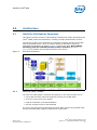
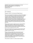
Different Components of the Intel® BLDK
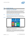
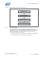
The Intel® BLDK consists of several components including source/binary code,
development tool and documentation, shown in Figure 1. Together these components
enable you to build a customized boot loader solution for your specific target platform.
Figure 1.
Intel® BLDK Overview
Code base - The Intel® BLDK consists of a collection of packages providing a reference
firmware implementation of the boot loader for specific Customer Reference Boards
(CRBs), which can then be used as a starting point to create customized
implementations for your specific target system.
Development tool - The Intel® BLDK development application provides a single
integrated environment, with tools and control environments for developing customized
firmware boot loaders. It includes a Graphical User Interface (GUI) to build the boot
loader firmware and to customize binary images. Using the development application
you can perform the following tasks:
January 2012
Document Number: 325926-003
Intel® Boot Loader Development Kit
Version 2.0 — UEFI Standard Based User Guide
9
Intel® BLDK—Product Overview
• Create projects to customize and organize your firmware images for your specific
target boards.
• Enable, disable, and configure firmware features in a binary image without
removing code from the image.
• Utilize Boot Setting Files (BSF), see Section 5.0, to establish a known configuration
as a derivative of the base image on new binary images.
• Use the built-in source code editor with syntax highlighting for source-level
changes of boot image when source code is available.
• Initiate source-level builds of an image when source code is available by spawning
a build process.
In addition, the Intel® BLDK also includes a software only debugger solution, see
Section 6.1, with the familiar WinDbg* front-end enabling faster implementation and
debug.
Documentation - The Intel® BLDK contains comprehensive instructional documents
including the Intel® Boot Loader Development Kit Version 2.0 — UEFI Standard Based
Getting Started Guide and the Intel® Boot Loader Development Kit User Guide (this
document).
Intel® Boot Loader Development Kit
Version 2.0 — UEFI Standard Based User Guide
10
January 2012
Document Number: 325926-003
Intel® BLDK and Intel® UDK2010—Intel® BLDK
3.0
Intel® BLDK and Intel® UDK2010
3.1
Open Source Availability
The Intel® BLDK code base is built on the Intel® UEFI Development Kit 2010 (Intel®
UDK2010), which is open source firmware and is available at the website:
www.tianocore.org. Table 4 lists packages from the open source Intel® UDK2010
included in the Intel® BLDK.
For details on the version of Intel® UDK2010 used in the Intel® BLDK release, refer to
the Release Notes provided with the Customer Reference Board (CRB) package.
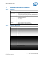
Table 4.
Intel® UDK2010 Packages Included in the Intel® BLDK
Package Name
3.2
Description
BaseTools
Provides build related tools
EdkShellBinPkg
Contains multiple binary shell applications that follow UEFI specifications
IntelFrameworkModulePkg
Definitions and module implementations that follow Intel EFI Framework
Specification
MdeModulePkg
Provides the modules that conform to UEFI/PI industry standards
MdePkg
All definitions (including functions, MACROs, structures and library classes) and
libraries instances, that are defined in MDE Specification
PcAtChipsetPkg
PC-AT standard defined device drivers; e.g., 8254, 8259
SourceLevelDebugPkg
Debug agent
UefiCpuPkg
Provides UEFI compatible CPU modules and libraries
Intel® BLDK Features
The Intel® BLDK provides the following main features:
• CPU, Memory, Basic I/O Initialization
• Boot from SATA, SD, USB
• Feature configuration via the Development Application
• Boot to Linux* OSes, Embedded OSes, UEFI Shell 2.0
• Windows* Tool Chain
• GCC* Tool Chain (Linux* Source Package)
• UEFI Specification version 2.3 and PI Specification version 1.2
• Fast Boot
• Pre-boot graphics (splash screen)
• TCP/IP File Transfer
• ACPI 3.0
• Supports the Intel® UEFI Development Kit Debugger Tool
January 2012
Document Number: 325926-003
Intel® Boot Loader Development Kit
Version 2.0 — UEFI Standard Based User Guide
11
Intel® BLDK—Intel® BLDK and Intel® UDK2010
• HD Audio
• Enhanced Intel SpeedStep® Technology
• Intel® Hyper-Threading Technology
• Processor virtualization (VT-x)
Intel® Boot Loader Development Kit
Version 2.0 — UEFI Standard Based User Guide
12
January 2012
Document Number: 325926-003
Architecture—Intel® BLDK
4.0
Architecture
4.1
Platform Initialization Sequences
This section provides a basis for understanding the Intel® Boot Loader Development Kit
(Intel® BLDK) code base architectures, including concepts and definitions of terms.
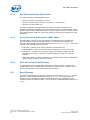
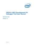
The primary purpose of the code base is to initialize a platform and boot to the UEFI
Shell or operating system. There are multiple phases of operations required to
accomplish this objective, as shown in Figure 2. Refer to the book, Beyond BIOS:
Developing with the Unified Extensible Firmware Interface (see Table 1 on
page 5), for full details of the phases described in this section.
Figure 2.
Boot Process Phases
4.1.1
Security (SEC) Phase
The code in the SEC phase is executed during power on. Its main functions are to:
• set up data and stack cached as temporary memory for the PEI phase
• serve as a root of trust in the system
• hand off information to the PEI Foundation
• discover and pass control to the PEI Phase
It is during this phase that the bootstrap processor (BSP) switches to protected mode
and the microcode patch update is performed on all the CPUs.
January 2012
Document Number: 325926-003
Intel® Boot Loader Development Kit
Version 2.0 — UEFI Standard Based User Guide
13
Intel® BLDK—Architecture
4.1.2
Pre-EFI Initialization (PEI) Phase
The main functions of the PEI Phase are to:
• initialize memory and platform resources
• discover the boot mode (recovery, S3 resume, or normal boot)
• discover and launch DXE core
The main component in the PEI Phase is the PEI Core which is responsible for
dispatching PEI Modules (PEIM) and providing basic services. The PEI Modules collect
platform features and configuration data in a series of data structures in memory called
the Hand Off Blocks (HOB) list, which gets passed as read-only from PEI phase to the
DXE phase.
4.1.3
Driver Execution Environment (DXE) Phase
The DXE Phase is where most of the platform gets initialized and it provides the
services required to boot an operating system. As described in the UEFI Driver
Execution Environment Core Interface specification (see Table 1 on page 5), this phase
consists of the following DXE components:
• DXE Core - produces a set of Boot, Runtime, and DXE Services.
• DXE Dispatcher - discovers and executes the DXE drivers in the correct order.
• DXE Drivers - initializes the processor, chipset, and platform components and
provides the Architecture Protocols (AP) that abstract the DXE core from the
platform.
• EFI System Table - contains the pointers to all the EFI service tables, configuration
tables, handle database, and console device.
4.1.4
Boot Device Select (BDS) Phase
The BDS Phase is where the platform boot policy is determined for executing the
selected boot option. The BDS phase initializes the console devices, loads the device
drivers, and attempts to load and execute boot selections.
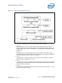
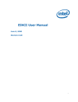
4.2
Boot Process
The Intel® BLDK follows the same boot sequence as described in Section 4.1, and as
depicted in the Non-Optimized Boot sequence of Figure 3. The Intel® BLDK boot
process provides the ability to optimize the boot sequence by initializing only the
hardware required to boot the target. This is shown in the Optimized Boot sequence of
Figure 3.
Intel® Boot Loader Development Kit
Version 2.0 — UEFI Standard Based User Guide
14
January 2012
Document Number: 325926-003
Architecture—Intel® BLDK
Figure 3.
Optimized and Non-Optimized Boot Process Flow
Non-Optimized Boot
Optimized Boot
SEC Phase
SEC Phase
Pre-memory early initialization, microcode
patching, and MTRR programming.
Pre-memory early initialization, microcode
patching, and MTRR programming.
PEI Phase
PEI Phase
Dispatches various PEI drivers. Pre-memory early
initialization, microcode patching, and MTRR programming.
Dispatches only minimal PEI drivers.
Pre-memory early initialization, microcode
patching, and MTRR programming.
Yes
O/S Resume Vector
In S3 Boot
mode?
No
Yes
O/S Resume Vector
In S3 Boot
mode?
No
DXE + BDS Phase
DXE + BDS Phase
Discover all drivers available to the platform.
Dispatch all drivers encountered.
4.3
Discover the drivers available to the platform.
Dispatch only the minimal drivers required to
boot the target
Types of Intel® BLDK Files
The Intel® BLDK package includes several infrastructure files in addition to the source
files. These include the following:
• ACPI - Advanced Configuration and Power Interface File
The ACPI file is compiled from C files which contain static data table only (no code)
and contains binary ACPI tables (typically mapped to FACS, FADT, MCFG, HPET, and
others). See the ACPI specification in Table 1 on page 5 for details.
• AML - ACPI Machine Language File
The AML file is compiled from ACPI Source Language (ASL) files and contains
binary ACPI tables (typically mapped to SSDT and DSDT tables). See the ACPI
specification in Table 1 on page 5 for details.
• BSF - Boot Setting File
The Boot Setting File (BSF) is a text file that contains the configuration options
available for update using the Intel® BLDK Development Application. For details,
see Chapter 5.0, “Intel® BLDK BSF - Introduction.”
• DEC - Package declaration file
The DEC file declares interfaces available from a package, including GUIDs,
protocols, PPIs, and PCDs. A detailed description of the DEC file (EDK II DEC File
Specification) is available on www.tianocore.org.
• DEPEX - Dependency Expression File
The DEPEX file defines the dependencies that must be true prior to loading the
driver.
January 2012
Document Number: 325926-003
Intel® Boot Loader Development Kit
Version 2.0 — UEFI Standard Based User Guide
15
Intel® BLDK—Architecture
• DSC - Platform description file
The DSC file describes the build rules, libraries, and components that are used to
generate the firmware image for the platform target. A detailed description of the
DSC file (EDK II DSC File Specification) is available on www.tianocore.org.
• EFI - Extensible Firmware Interface File
The EFI file is an executable driver or Shell application binary.
• FDF - Flash description file
The FDF file describes how to package the build output generated using the DSC,
along with any additional binary files, for the flash device. A detailed description of
the FDF file [EDK II Flash Description (FDF) File Specification] is available on
www.tianocore.org.
• INF - Module definition file
The INF defines all required information for a single item. A detailed description of
the INF file (EDK II INF File Specification) is available on www.tianocore.org.
• VPD - Virtual Product Data File
The VPD file contains the VPD database in binary form. The BSF file is converted
into a VPD file during the build process.
4.4
Protocol and Drivers
The Intel® BLDK code base consists of a collection of source and/or binary modules
from which you can build a boot loader for the target reference platform. Since the
Intel® BLDK is based on the Intel® UDK2010 source release, it follows the packaging
model of EDKII. For more details on EDKII packages and how to develop new EDKII
modules, refer to the EDK II Module Writer's Guide (see Table 1 on page 5). The
remainder of this section provides an introduction to some of the architectural concepts
of UEFI-based boot loaders.
At the basic level, a boot loader developed with the Intel® BLDK is made up of a set of
drivers and libraries that initialize the system and provide services to other drivers via
protocols. The UEFI Driver Writer’s Guide provides the following explanation of the
relationship between drivers and protocols:
“A UEFI driver is an executable UEFI image that installs a variety of protocols of
various handles to accomplish its job. UEFI protocols are a block of function
pointers and data structures or APIs that have been defined by a specification.”
A protocol is identified by a Globally Unique Identifier (GUID) that is defined in the
protocol specification. For example, the following is the definition of the component
name protocol which includes two function definitions and one data field:
GUID
#define EFI_COMPONENT_NAME2_PROTOCOL_GUID \
{0x6a7a5cff, 0xe8d9, 0x4f70, 0xba, 0xda, 0x75, 0xab, 0x30,\
0x25, 0xce, 0x14}
Protocol Interface Structure
typedef struct _EFI_COMPONENT_NAME2_PROTOCOL {
EFI_COMPONENT_NAME_GET_DRIVER_NAME
GetDriverName;
EFI_COMPONENT_NAME_GET_CONTROLLER_NAME
GetControllerName;
CHAR8
*SupportedLanguages;
} EFI_COMPONENT_NAME2_PROTOCOL;
A driver locates a protocol, such as the EFI component name protocol, using standard
UEFI services such as those defined in Table 5. For more details on locating and using
protocols, refer to Section 6.3 of the UEFI specification (see Table 1 on page 5).
Intel® Boot Loader Development Kit
Version 2.0 — UEFI Standard Based User Guide
16
January 2012
Document Number: 325926-003
Architecture—Intel® BLDK
Table 5.
Sample Protocol Interface Functions
Name
Type
Description
InstallProtocolInterface
Boot
Installs a protocol interface on a device handle
UninstallProtocolInterface
Boot
Removes a protocol interface from a device handle
RegisterProtocolNotify
Boot
Registers an event that is to be signaled whenever an interface is
installed for a specified protocol
LocateHandle
Boot
Returns an array of handles that support a specified protocol
HandleProtocol
Boot
Queries a handle to determine if it supports a specified protocol
LocateProtocol
Boot
Finds the first handle in the handle database that supports the
requested protocol
For further information on developing UEFI drivers for your system, refer to the UEFI
Driver Writer's Guide and the sample drivers provided as part of the Intel® UDK2010
release.
4.5
UEFI Services
The Intel® BLDK includes an implementation of the UEFI specification and the critical
services defined in that specification. These services are divided into two distinct
categories: Boot Services and Runtime Services. These are defined as follows in the
UEFI specification:
• Boot Services: Functions that are available before a successful call to
ExitBootServices(). These functions are described in Section 6 of the UEFI
specification.
• Runtime Services: Functions that are available before and after any call to
ExitBootServices(). These functions are described in Section 7 of the UEFI
specification.
Boot and Runtime services are accessed via a pointer to the EFI System Table which is
passed as a standard argument to driver entry points. The EFI System Table is defined
in the UEFI specification in Section 4 as:
typedef struct {
EFI_TABLE_HEADER
CHAR16
UINT32
EFI_HANDLE
EFI_SIMPLE_TEXT_INPUT_PROTOCOL
EFI_HANDLE
EFI_SIMPLE_TEXT_OUTPUT_PROTOCOL
EFI_HANDLE
EFI_SIMPLE_TEXT_OUTPUT_PROTOCOL
EFI_RUNTIME_SERVICES
EFI_BOOT_SERVICES
UINTN
EFI_CONFIGURATION_TABLE
} EFI_SYSTEM_TABLE;
Hdr;
*FirmwareVendor;
FirmwareRevision;
ConsoleInHandle;
*ConIn;
ConsoleOutHandle;
*ConOut;
StandardErrorHandle;
*StdErr;
*RuntimeServices;
*BootServices;
NumberOfTableEntries;
*ConfigurationTable;
The following is an example of a driver entry point from the WatchDogTimerDxe
driver (from MdeModulePkg\Universal\WatchdogTimerDxe\WatchdogTimer.c)
with the EFI System Table passed as an argument:
EFI_STATUS
EFIAPI
WatchdogTimerDriverInitialize(
January 2012
Document Number: 325926-003
Intel® Boot Loader Development Kit
Version 2.0 — UEFI Standard Based User Guide
17
Intel® BLDK—Architecture
IN EFI_HANDLE ImageHandle,
IN EFI_SYSTEM_TABLE *SystemTable
)
The EDK II implementation then provides access to Boot and Runtime services through
standard libraries and via standard global variables (see EDK II Module Writer's Guide,
Section 5 for more details). Table 6 lists the global variables provided by those libraries.
Table 6.
Global Variables for UEFI Service Access
Name
Description
gST
Pointer to EFI System Table
gBS
Pointer to UEFI Boot Services
gRT
Pointer to UEFI Runtime Services
Examples of Boot and Runtime services are in Table 7. For a complete description of the
services provided by a UEFI-compliant implementation, refer to the UEFI specification.
Table 7.
Sample UEFI Services
Name
Type
Description
CreateEvent
Boot
Creates an Event
RaiseTPL
Boot
Raises a task's priority level and returns its previous value
AllocatePages
Boot
Allocates memory pages from the system
GetNextMonotonicCount
Boot
Returns a monotonically increasing count for the platform
LoadImage
Boot
Loads an EFI image into memory
ExitBootServices
Boot
Terminates all boot services
GetVariable
Runtime
Returns the value of a variable
SetVariable
Runtime
Sets the value of a variable
SetVirtualAddressMap
Runtime
Changes the runtime addressing mode of EFI firmware from physical
to virtual
ConvertPointer
Runtime
Determines the new virtual address that is to be used on subsequent
memory accesses
Using the concepts introduced above, the following example demonstrates how a UEFI
Boot Service can be called from a driver entry point (the example is taken from the
WatchDogTimerDxe driver in the MdeModulePkg):
EFI_STATUS
EFIAPI
WatchdogTimerDriverInitialize(
IN EFI_HANDLE ImageHandle,
IN EFI_SYSTEM_TABLE *SystemTable
)
{
EFI_STATUS Status;
//
// Make sure the Watchdog Timer Architectural Protocol has not been
// installed in the system yet.
//
ASSERT_PROTOCOL_ALREADY_INSTALLED(
NULL,
&gEfiWatchdogTimerArchProtocolGuid
);
//
// Create the timer event to implement a simple watchdog timer
//
Intel® Boot Loader Development Kit
Version 2.0 — UEFI Standard Based User Guide
18
January 2012
Document Number: 325926-003
Architecture—Intel® BLDK
Status = gBS->CreateEvent (
EVT_TIMER | EVT_NOTIFY_SIGNAL,
TPL_NOTIFY,
WatchdogTimerDriverExpires,
NULL,
&mWatchdogTimerEvent
);
ASSERT_EFI_ERROR (Status);
//
// Install the Watchdog Timer Arch Protocol onto a new handle
//
Status = gBS->InstallMultipleProtocolInterfaces (
&mWatchdogTimerHandle,
&gEfiWatchdogTimerArchProtocolGuid,
&mWatchdogTimer,
NULL
);
ASSERT_EFI_ERROR (Status);
return EFI_SUCCESS;
}
January 2012
Document Number: 325926-003
Intel® Boot Loader Development Kit
Version 2.0 — UEFI Standard Based User Guide
19
Intel® BLDK—Intel® BLDK BSF - Introduction
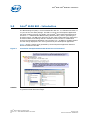
5.0
Intel® BLDK BSF - Introduction
The Boot Setting File (BSF) is a text metadata file with the .bsf filename extension. It
is a part of the code base package. The BSF is used by the Development Application
tool when creating projects (for details, see the Intel® Boot Loader Development Kit
Version 2.0 — UEFI Standard Based Getting Started Guide), and for generating the
firmware images. The BSF, also referred to as the image configuration file, defines the
firmware features and settings that are available to the end user for modification
through the Development Application user interface (UI). In addition, the BSF contains
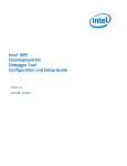
the text strings displayed in the views generated by the development application.
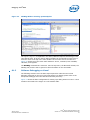
Figure 4 shows a sample view generated by the development application based on
directives defined in the BSF.
Figure 4.
Correlation Example Between BSF Directives and UI Control
Caution:
The end user must not modify the BSF since this can cause the build to fail or the tool
to generate invalid firmware images.
Intel® Boot Loader Development Kit
Version 2.0 — UEFI Standard Based User Guide
20
January 2012
Document Number: 325926-003
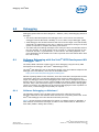
Debugging—Intel® BLDK
6.0
Debugging
Debugging options fall into three categories: software, JTAG, and debugging without a
debugger.
• The Intel® UEFI Development Kit Debugger Tool is a full source level software
debugger based on Microsoft* WinDbg* or Linux* GNU* Project Debugger (GDB).
• JTAG debuggers are hardware devices that connect to the target via a JTAG header,
specifically the XDP header in this case. A software component running on the host
system is required to complete the debug environment.
• The UEFI code prints debug messages to the serial port and it sends POST codes to
the port 80 LEDs. The serial output can be received by a terminal program on the
host such as Putty*, HyperTerminal*, or Terra Term*. For debug purposes, new
print statements can be added to the code to provide more information about what
the code is doing.
6.1
Software Debugging with the Intel® UEFI Development Kit
Debugger Tool
The Intel® BLDK code base supports source level debugging using the Intel® UEFI
Development Kit Debugger Tool (Intel® UDK Debugger Tool).
The Intel® UDK Debugger Tool is described at length in the Intel UEFI Development Kit
Debugger Tool User Manual, which can be downloaded from:
http://www.intel.com/technology/efi/sw-debug.htm
Without repeating details in this document, there are some basic concepts that must be
understood. Since this is a software debugger that requires a debug agent on the
target, the debugger cannot start debugging at the reset vector. The agent will have to
become active in a memory space (cache as RAM at the earliest) before the debugger
will work. Also, if the code on the target is unstable to the point that the debug agent
cannot run properly, the debugger will be useless at debugging this kind of problem. In
these cases, a JTAG debugger will probably be required.
6.1.1
Software Debugging on Windows*
The following sections cover the basic steps required to make the source level
debugger functional on the Windows Host environment. For details, please refer to the
Intel® UDK Debugger Tool User Manual mentioned previously.
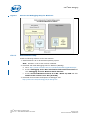
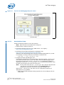
Figure 5 shows the basic configuration for setting up a debug session on Windows: a
host machine connected to the target via either a null-modem cable or USB host-tohost cable (USB 2.0 debug device cable).
January 2012
Document Number: 325926-003
Intel® Boot Loader Development Kit
Version 2.0 — UEFI Standard Based User Guide
21
Intel® BLDK—Debugging
Figure 5.
Source Level Debugging Setup for Windows*
6.1.1.1
Host Machine Setup
Install the following software on the host machine:
1. Install Windows* XP 32-bit with SP3 operating system.
Note: Windows* 7 64-bit has not been validated.
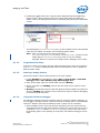
2. Download and install Debugging Tools for Windows (WinDbg):
a.
Go to: http://msdn.microsoft.com/en-us/windows/hardware/gg463009.aspx
b.
Scroll to Debugging Tools: More Information and Previous Versions and
click: Debugging Tools for Windows 32-bit Versions
c.
Scroll to Previous Release version 6.11.1.404 - March 27, 2009 and click:
Install 32-bit version 6.11.1.404 [16.9 MB]
3. Download the Intel UEFI Development Kit Debugger Tool:
http://www.intel.com/technology/efi/sw-debug.htm
Intel® Boot Loader Development Kit
Version 2.0 — UEFI Standard Based User Guide
22
January 2012
Document Number: 325926-003
Debugging—Intel® BLDK
4. Install Intel® BLDK code base. Using the Intel® BLDK Development Application,
build the Intel® BLDK code base with source level debug feature enabled. For
details, refer to the Getting Started Guide, specifically the Selecting the Build Mode
section.
The Debug Agent (SourceLevelDebugPkg) is also installed when the Intel® BLDK
code base is installed. For details, see the Getting Started Guide.
Note: After you finish the build, check the directory
Build\CrownBayPlatform\DEBUG_VS2008x86\IA32, to make sure the
Debug Agent SourceLevelDebugPkg exists. If not, the software
debugger feature is not built in the image and the debugger will not work.
6.1.1.2
Target Machine Setup
Program the flash on the target with the debug firmware image, which was created in
Section 6.1.1.1. See the Getting Started Guide for information on how to update the
BLDK firmware image.
6.1.1.3
Starting a Debug Session
Follow these steps to start a debug session on the host machine:
1. Launch WinDbg from Windows by clicking Start > All Programs > Intel UDK
Debugger Tool > Start WinDbg using UDK Debugger Tool
2. Start up the target within 30 seconds after launching WinDbg.
3. Wait 2-3 seconds until WinDbg connects with the target and is ready to accept
commands.
4. WinDbg should stop the target at late SEC phase and have loaded the symbols for
SecCore. WinDbg then shows the source code and is ready for software debugging
of the Intel® BLDK code base.
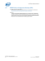
6.1.1.4
Using the Software Debugger
The following example shows the necessary steps for using the software debugger. In
this example, the target customer reference board is the Intel® Atom™ Processor E660
with Intel® Platform Controller Hub EG20T, which is referred to as Crown Bay.
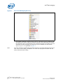
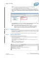
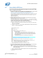
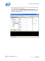
1. After the EDK II source code tree has been installed on the host system and the
development tools have also been installed, examine the source code tree. There is
a directory in Figure 6 called SourceLevelDebugPkg, which is the code for the
target debug agent. If this package is not present, the software debugger will not
work.
January 2012
Document Number: 325926-003
Intel® Boot Loader Development Kit
Version 2.0 — UEFI Standard Based User Guide
23
Intel® BLDK—Debugging
Figure 6.
SourceLevelDebugPkg Directory
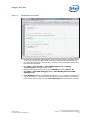
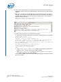
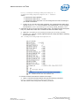
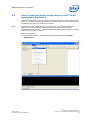
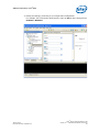
2. The software debugger requires CpuBreakpoint and CpuDeadLoop function calls
inserted into the source code at a location of interest. The dead loop is an infinite
loop that will require an adjustment to the instruction pointer to get past, but it will
guarantee that the debugger will stop there. For our example, we will use the
CpuBreakpoint as illustrated in Figure 7.
Note:
You must rebuild the Intel® BLDK code base whenever you make changes to the source
code, such as when adding breakpoints. You must also reprogram the flash with the
newly created firmware image.
Intel® Boot Loader Development Kit
Version 2.0 — UEFI Standard Based User Guide
24
January 2012
Document Number: 325926-003
Debugging—Intel® BLDK
Figure 7.
CpuBreakpoint Example
3. Connect the null modem cable between the host and the target. The location of the
serial port connector is board-specific and may be different between targets. For
the Crown Bay CRB target, for example, connect the null modem cable to the lower
left serial port connector.
4. Click Start > All Programs > Intel UDK Debugger Tool > Change
Configurations to set flow control to zero.
5. With the target board powered off, launch WinDbg by clicking Start > All
Programs > Intel UDK Debugger Tool > Start WinDbg with Intel UDK
Debugger Tool.
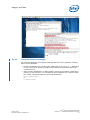
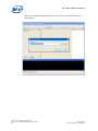
6. When WinDbg launches, a command window like Figure 8 will pop up. After three
or four dots, power on the target board and press the power button on the board. If
there seems to be a hang, look for a Save Workspace pop-up behind the window.
January 2012
Document Number: 325926-003
Intel® Boot Loader Development Kit
Version 2.0 — UEFI Standard Based User Guide
25
Intel® BLDK—Debugging
Figure 8.
Windbg Launch Window
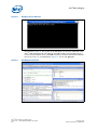
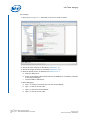
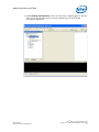
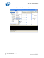
7. Once the WinDbg connection is established, the source code will look like the top
left window in Figure 9. This is part of the debugger set up and is explained in the
Intel® UDK Debugger Tool User Manual. Click go so that it will proceed and let it
run for several seconds. Then, click halt. The source window should have halted at
the CpuBreakpoint as illustrated in Figure 10. If not, click go again.
Figure 9.
WinDbg Main Window
Intel® Boot Loader Development Kit
Version 2.0 — UEFI Standard Based User Guide
26
January 2012
Document Number: 325926-003
Debugging—Intel® BLDK
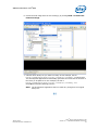
Figure 10.
WinDbg Window showing CpuBreakpoint
The CpuBreakpoint is explained in the Intel® UEFI Development Kit Debugger Tool
User Manual. Also, all of the various debug windows can be opened from the icons or
from the menu at the top of the main window. Click on each one to see what it is.
Figure 10 shows five of the most useful windows: source, command, local variables,
call stack, and registers.
The WinDbg commands are extensive. Use the help menu, the Microsoft website, the
WinDbg wiki, and the web in general to find information on the commands.
6.1.2
Software Debugging on Linux*
The following sections cover the basic steps required to make the source level
debugger functional on the Linux Host environment. For details, please refer to the
Intel® UDK Debugger Tool User Manual mentioned previously.
Figure 11 shows the basic configuration for setting up a debug session on Linux: a host
machine connected to the target via a null-modem cable.
January 2012
Document Number: 325926-003
Intel® Boot Loader Development Kit
Version 2.0 — UEFI Standard Based User Guide
27
Intel® BLDK—Debugging
Figure 11.
Source Level Debugging Setup for Linux*
6.1.2.1
Host Machine Setup
Install the following software on the host machine:
Note: Make sure the host machine has a COM port.
1. Install Timesys* Fedora* Remix 14.
2. Download Debugging Tools for Linux (GDB version 7.0 or higher):
http://www.gnu.org/software/gdb/
3. Download the Intel UEFI Development Kit Debugger Tool:
http://www.intel.com/technology/efi/sw-debug.htm
Install the Intel UDK Debugger Tool using the command appropriate for your OS.
For example, in Timesys, enter this command to install the tool:
sudo rpm -i <host installer>.rpm
4. Configure the Intel UDK Debugger Tool.
Configuration information for the host system is stored in the file .udkdebugger
in the home directory of the current user. When the Intel UDK Debugger Tool is
launched for the first time, the file .udkdebugger is automatically created by
copying the contents of /etc/udkdebugger.conf into the home directory. (This
file does not exist prior to the first use of the tool.)
Note: You may have more than one .udkdebugger file in the OS. Note well that
.udkdebugger in the home directory of the current user is the
configuration setting file used by the Intel UDK Debugger Tool.
Open the file .udkdebugger and make sure the configuration settings are
appropriate for your platform:
— Make sure the Debug Port/Port setting specifies the correct COM port for the
debug cable.
Intel® Boot Loader Development Kit
Version 2.0 — UEFI Standard Based User Guide
28
January 2012
Document Number: 325926-003
Debugging—Intel® BLDK
Note: For details on other configuration items, refer to the Intel UEFI
Development Kit Debugger Tool User Manual.
5. Install Intel® BLDK code base. Using the Intel® BLDK Development Application,
build the Intel® BLDK code base with the source level debug feature enabled. For
details, refer to the Getting Started Guide, specifically the Selecting the Build Mode
section.
The Debug Agent (SourceLevelDebugPkg) is also installed when the Intel® BLDK
code base is installed. For details, see the Getting Started Guide.
Note: After you finish the build, check the directory /Build/
CrownBayPlatform/DEBUG_GCC45/IA32, to make sure the Debug
Agent SourceLevelDebugPkg exists. If not, the software debugger
feature is not built in the image and the debugger will not work.
6.1.2.2
Target Machine Setup
• Program the flash on the target with the debug firmware image, which was created
in Section 6.1.2.1. See the Getting Started Guide for information on how to update
the BLDK firmware image.
• Connect the Host Machine to the Target Machine using a null-modem cable.
6.1.2.3
Starting a Debug Session
Follow these steps to start a GDB debug session:
1. At the terminal shell prompt, start the GDB server by entering the appropriate
command, similar to this:
[root@localhost ~]# [/usr/bin/]udk-gdb-server
The command line is a symbolic link to /opt/intel/udkdebugger/bin/udk-
gdb-server
Note: You must be logged in as root.
The following message is displayed:
January 2012
Document Number: 325926-003
Intel® Boot Loader Development Kit
Version 2.0 — UEFI Standard Based User Guide
29
Intel® BLDK—Debugging
2. Power up the target system. The system must include the UDK-based firmware
image built with the source-level debug package, and must have the debug feature
enabled.
3. Wait for 1 or 2 seconds until the GDB server successfully connects to the target
debugger. You should see a message similar to the one shown below. The message
indicates that the GDB server has successfully connected and, in this example, is
listening on TCP port 1234.
GdbServer on <HOST> is waiting for connection on port 1234
Connect with 'target remote <HOST>:1234'
4. Connect GDB to GDB Server using the following steps:
a.
Start a new terminal window and run gdb at the shell prompt to start the GDB:
[bldk@localhost ~]$ gdb
GNU gdb (GDB) Fedora (7.2-52.fc14)
Copyright (C) 2010 Free Software Foundation, Inc.
License GPLv3+: GNU GPL version 3 or later <http://gnu.org/licenses/gpl.html>
This is free software: you are free to change and redistribute it.
There is NO WARRANTY, to the extent permitted by law. Type "show copying" and
"show warranty" for details.
This GDB was configured as "i686-redhat-linux-gnu".
For bug reporting instructions, please see:
<http://www.gnu.org/software/gdb/bugs/>.
(gdb)
b.
Type target remote <HOST>:1234 in GDB as prompted by the GDB server.
Replace <HOST> with the name of your target machine.
Type source /opt/intel/udkdebugger/bin/udk-gdb-script to load
the GDB extension for Intel UDK Debugger.
You can now use GDB extension commands to begin debugging the target firmware
at the source level.
c.
Intel® Boot Loader Development Kit
Version 2.0 — UEFI Standard Based User Guide
30
January 2012
Document Number: 325926-003
Debugging—Intel® BLDK
6.1.2.4
Using the Software Debugger
The Intel UDK Debugger Tool supports GDB operations for Linux platforms, including
these critical operations:
• Embed a breakpoint in the source code. Adding the CpuBreakpoint() statement
to your source code, allows the GDB to enter interactive mode when the target
executes the line.
• Add a function breakpoint in a debug session. As long as a module’s symbol file is
loaded, you can use the break command to set a breakpoint for a function within
the module. Command syntax for the break command is:
break <function_name>
or
b <function_name>
January 2012
Document Number: 325926-003
Intel® Boot Loader Development Kit
Version 2.0 — UEFI Standard Based User Guide
31
Intel® BLDK—Debugging
For example:
1. Add a CpuBreakpoint() statement in the source code as shown:
2. Set up the host machine as described in Section 6.1.2.1.
3. Set up the target machine as described in Section 6.1.2.2.
4. Start the debug session as described in Section 6.1.2.3.
a.
Start the GDB server.
b.
Power up the target system and make sure the GDB server successfully connects
to the target debugger.
c.
Connect GDB to GDB Server.
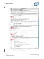
5. Start debugging:
a.
Type c to continue execution and run into the breakpoint.
b.
Type l to list the source code.
c.
Type n to step over the breakpoint.
d.
Type l to list the source code.
Intel® Boot Loader Development Kit
Version 2.0 — UEFI Standard Based User Guide
32
January 2012
Document Number: 325926-003
Debugging—Intel® BLDK
e.
Type b PciHostBridgeP2CProcess to set breakpoint for function
PciHostBridgeP2CProcess().
f.
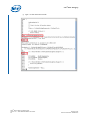
Type c to stop the execution at the breakpoint.
January 2012
Document Number: 325926-003
Intel® Boot Loader Development Kit
Version 2.0 — UEFI Standard Based User Guide
33
Intel® BLDK—Debugging
g.
Type l to list more source code.
Intel® Boot Loader Development Kit
Version 2.0 — UEFI Standard Based User Guide
34
January 2012
Document Number: 325926-003
Debugging—Intel® BLDK
6.2
Platform Level Debugging using JTAG/ITP
JTAG debugging can be done from your host development machine to the target if the
target has an In-Target Probe (ITP) header, as shown in Figure 12.
Figure 12.
Platform Level Debugging Setup
JTAG debuggers do not require placing a software debug agent on the target to work
and consequently do not have the limitations that the software debugger has. JTAG
debuggers can examine the code from the reset vector forward.
The customer reference boards for the Intel® Atom™ processors have an XDP
connector, which is used by the In-Target Probe (ITP). The customer’s selected JTAG
debugger will need to use this connector.
To do source level debug, a debug build rather than a release build of the code is
required. Be sure that the -b DEBUG option is in the build command.
There are several third-party JTAG vendors that support JTAG debugging on Intel®
processors. The product pricing and feature sets vary significantly. For information,
please contact the vendors directly.
• Arium*: http://www.arium.com/
• Green Hills Software*: http://www.ghs.com/
• Lauterbach*: http://www.lauterbach.com/frames.html?home.html
• Macraigor Systems: http://www.macraigor.com/
• Wind River*: http://www.windriver.com/
January 2012
Document Number: 325926-003
Intel® Boot Loader Development Kit
Version 2.0 — UEFI Standard Based User Guide
35
Intel® BLDK—OS Bring-up
7.0
OS Bring-up
7.1
OS Hand-Off Requirements
This section discusses the special considerations that are required when writing a UEFI
OS loader. An OS loader is a special type of UEFI application responsible for
transitioning a system from a firmware environment into an OS runtime environment.
The OS loader must perform the following tasks:
1. The OS loader must determine from where it was loaded, so that it can retrieve
additional files from the same location.
2. The OS loader must determine where in the system the OS exists.
Typically, the OS resides on a partition of a hard drive, however, this partition may
not use a file system that is recognized by the UEFI environment. In this case, the
OS loader can only access the partition as a block device using block I/O
operations. The OS loader will then be required to implement or load the file
system driver to access files in the OS partition.
3. The OS loader must build a memory map of the physical memory resources so that
the OS kernel can know what memory to manage. The OS loader can use the UEFI
APIs to retrieve the system’s current memory map, because some of the physical
memory in the system must remain untouched by the OS kernel.
4. The OS loader retrieves system configuration information from the System Table
data structure that is passed in. The System Table informs the OS loader about:
— services available from the platform firmware, such as block and console
services for loading the OS kernel binary from media and interacting with the
user prior to the OS drivers are loaded, respectively.
— access to industry standard tables like ACPI, SMBIOS, and others.
5. The OS loader may need to access environment variables such as boot paths and
boot options that are stored in nonvolatile storage. In addition, the OS loader may
be required to pass some of the environment variables to the OS kernel.
6. Next, either the OS loader or the OS kernel calls the ExitBootServices()
function. Special care must be taken to guarantee that the most current memory
map has been retrieved prior to making this call. Once ExitBootServices() has
been called, no more UEFI Boot Services calls can be made. At some point, either
just prior to calling ExitBootServices() or just after, the OS loader will transfer
control to the OS kernel.
7. After ExitBootServices() has completed, EFI Boot Services calls are no longer
available which indicates an OS kernel has taken control of the system. The OS
kernel may only call EFI Runtime Services.
Intel® Boot Loader Development Kit
Version 2.0 — UEFI Standard Based User Guide
36
January 2012
Document Number: 325926-003
Additional Information—Intel® BLDK
Appendix A Additional Information
Note:
The examples in this document are for the Intel® Atom™ Processor E660 with Intel®
Platform Controller Hub EG20T, which is referred to as Crown Bay.
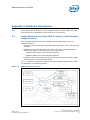
A.1
Image Build Process Flow (EDK-II centric) and Firmware
Image Creation
The Intel BLDK image build process is handled in three major stages which are
summarized below:
• AutoGen: the build tool parses meta-data files to generate C source code files and
makefiles.
• $(MAKE): the build tool processes the source code files to create PE32/PE32+/
COFF images that are converted to EFI format using either:
— NMAKE for Microsoft* OS development platforms
— MAKE for UNIX* style OS development platforms
• ImageGen: the build tool takes the EFI format files and creates EFI Flash images,
UEFI applications, or EFI PCI Option ROMs.
Figure 13 shows the relationships between these three stages. Details of each stage
are described in the following sections.
Figure 13.
EDK II Build Process Flow
January 2012
Document Number: 325926-003
Intel® Boot Loader Development Kit
Version 2.0 — UEFI Standard Based User Guide
37
Intel® BLDK—Additional Information
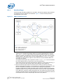
A.1.1
AutoGen Stage
In the first step of building a platform or a module, the build tool parses meta-data files
to generate C source code files and makefiles. Figure 14 shows the steps that are
accomplished by this stage.
Figure 14.
EDK II AutoGen Process
Key:
• DSC = platform description file
• INF = module description file
• FDF = flash description file
• DEC = declaration file
1. The first file the build tool looks for is $(WORKSPACE)/Conf/target.txt, where
(WORKSPACE)indicates the location where your project parameter file is stored.
The target.txt file is used to define the following: platform DSC file, build tag
(debug or release), architecture (such as IA-32 or x64), tool chain (such as Visual
Studio version), and build rule file. All the configurations in target.txt can be
overridden by command line options of the build tool. See the Release Notes for
command line options.
If no platform description file is specified in either target.txt or in the command
line, the build tool will try to find one in the current directory.
If the build tool finds a module description file (INF file) in the current directory, it
will try to build only that module rather than building a whole platform.
2. Once the build tool gets what to build and how to build, it starts to parse the
platform description file (DSC). From the DSC file, the build tool will locate the INF
files for all modules and libraries, as well as other settings of the platform
[including declaration file (DEC) specified default values for Platform Configuration
Databases (PCDs) used by modules and libraries that do not have values specified
in the DSC file]. Using the module description files, the build tool will find out what
package description files the module depends on. In this way, the build tool will find
out and parse all modules and packages that make up a platform.
Intel® Boot Loader Development Kit
Version 2.0 — UEFI Standard Based User Guide
38
January 2012
Document Number: 325926-003
Additional Information—Intel® BLDK
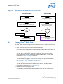
3. The next step is to generate the files required to build a module, including:
— AutoGen.h
— AutoGen.c (not generated for library modules)
— .depex (not generated for library modules; generated only if the module’s INF
file contains a [depex] section)
— makefile
Each module found in the DSC file will have a makefile generated for it. A top-level
makefile will be generated for the platform, from which all modules’ makefile will be
called.
Note:
When building a module, only a module makefile will be generated (a top-level makefile
will not be generated). Enter the following in the command line:
build -p target_platform_dsc_path -m target_module_inf_path
A.1.2
$(MAKE) Stage
The make stage processes the source files into EFI files, which starts out by building
required libraries, followed by the EDK components and finally, EDK II modules. The
outputs of this stage are linked PE32+/ COFF images that have been processed to
replace the standard header with an appropriate EFI header.
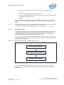
Figure 15 shows what will be done in the $(MAKE) stage from a platform point of view.
These tasks include building library modules, building non-library modules, and finally
generating flash image(s).
Figure 15.
EDK II Build Process - Platform Point of View
Build Library Modules
Build Non-Library Modules
Generate Flash Image
Figure 16 shows the $(MAKE) stage tasks from a module point of view, including
preprocessing, compiling or assembling, static/dynamic linking, and module image
generation.
January 2012
Document Number: 325926-003
Intel® Boot Loader Development Kit
Version 2.0 — UEFI Standard Based User Guide
39
Intel® BLDK—Additional Information
Figure 16.
EDK II Build Process - Module Point of View
Preprocess/Trim
Compile/Assemble
Static/Dynamic Link
Generate Module Images
A.1.3
ImageGen Stage
This stage processes the EFI files generated by the $(MAKE) stage into FLASH binary
images. The GenFds tool is typically called as the last step of a platform build's
$(MAKE) stage. The build.exe command will set up the call to GenFds and the Make
utility will call the program. The GenFds program can also be executed by the
developer from the command line as follows:
GenFds.exe [options] -f input_file -a arch_list -b build_target
-p active_platform -t tool_chain_tag -D “MacroName [=MacValue]”
Figure 17 shows the tools that are involved in the GenFds process.
Intel® Boot Loader Development Kit
Version 2.0 — UEFI Standard Based User Guide
40
January 2012
Document Number: 325926-003
Additional Information—Intel® BLDK
Figure 17.
FD Image Generation Process
GenFds calls the following tools during the generation of an FD image:
• GenSec
This application is used to generate valid EFI_SECTION type files from PE32/
PE32+/ COFF image files or other binary files. The utility will attach a valid section
or PEIM header to the input file as defined in the UEFI Platform Initialization (PI)
specification.
• GenFfs
This application is used to generate FFS files for inclusion in a firmware volume.
Rules specified in the FDF file stipulate how the FFS file will be organized (what kind
of sections should reside in it and in what format).
• GenFv
This application is used to generate an FV image by using information about the
FFS from the corresponding FV.inf file.
• GenFw
This application is used to generate UEFI firmware image files based on Component
or Module types listed in the INF files from the PE/PE32+/COFF images generated
by the third party tool chains.
• GenVtf
This application generates the Boot Strap File (also called Volume Top File, or VTF)
for IA32 X64, and IPF images.
January 2012
Document Number: 325926-003
Intel® Boot Loader Development Kit
Version 2.0 — UEFI Standard Based User Guide
41
Intel® BLDK—Additional Information
A.2
How to Build a UEFI Driver
This section describes how to build a new driver into the source tree of Intel® BLDK
Core for Crown Bay (UEFI Standard Based) and integrate it into the final boot loader
image. The detailed steps are below:
1. Develop a new UEFI driver using chapter three of the EDK II Module Writer's Guide
(version 0.7 or later). This document can be downloaded from:
http://sourceforge.net/projects/edk2/files/General%20Documentation/
In this example, we assume the name of your UEFI driver is Sampledrv and it is
running in the DXE phase. There are three driver files in the folder Sampledrv:
Sampledrv\Sampledrv.c
Sampledrv\Sampledrv.h
Sampledrv\Sampledrv.inf
2. Put your driver into the source tree by putting the driver folder into the target
platform package CrownBayPlatformPkg.
To build the sample driver, a reference to the driver's .inf file must be inserted
into the component's section of the target platform Description File (.DSC). In this
example, we are building the driver for IA-32 architecture.
Perform the following steps to add a reference to the UEFI driver.
a.
Open \CrownBayPlatformPkg\CrownBayPlatformPkg.dsc with a text
editor such as Notepad.
b.
Find the [Components.IA32] section (approximately line 849) and add your
driver’s .inf file as shown below.
c.
Save and close the CrownBayPlatformPkg.dsc file.
3. Execute the build command to build the driver. UDK2010 allows you to build one
driver in one build process with the command described below.
Note: This step is only to introduce the driver build command which may be
useful during driver development. It is not a necessary step to integrate a
driver into an image.
a.
Open a command prompt window and point to the source package directory.
b.
Type the following commands:
edksetup.bat
Intel® Boot Loader Development Kit
Version 2.0 — UEFI Standard Based User Guide
42
January 2012
Document Number: 325926-003
Additional Information—Intel® BLDK
build -p CrownBayPlatformPkg\CrownBayPlatformPkg.dsc -m
CrownBayPlatformPkg\SampleDrv\SampleDrv.inf -t VS2005x86
where:
-p specifies the target platform
-m specifies the target driver .inf file
-t specifies the target tool chain. You can change the tool chain according to
your build environment.
c.
If there is no error, after the build completes, the compiled binary UEFI driver
named SampleDrv.efi will be located in the build directory. In our example,
the directory is \Build\CrownBayPlatformPkg\DEBUG_MYTOOLS\IA32
4. Integrate the driver into the final boot loader image. The platform Flash Description
File (FDF) determines which file is included into the boot loader image.
a.
Open the \CrownBayPlatformPkg\CrownBayPlatformPkg.fdf file.
b.
Find the [FV.FVMAIN] section (approximately line 264) and add the following
line as shown below:
INF
CrownBayPlatformPkg/Sampledrv/Sampledrv.inf
5. Execute the build command to build the final image.
a.
Open a command prompt window and type the following command:
build -p CrownBayPlatformPkg\CrownBayPlatformPkg.dsc
This will build the final image which includes your driver.
January 2012
Document Number: 325926-003
Intel® Boot Loader Development Kit
Version 2.0 — UEFI Standard Based User Guide
43
Intel® BLDK—Additional Information
A.3
EDKII Platform Configuration Database (PCD)
For details, refer to the white paper:
EDKII Platform Configuration Database Entries: An Introduction to PCD Entries
http://download.intel.com/design/intarch/papers/325619.pdf
Summary:
A Platform Configuration Database (PCD) entry is a setting which is established
during the time that the platform BIOS/Boot-loader is built. In the case of a UEFI
compliant codebase, there are commonly defined interfaces for abstracting certain
types of PCDs. The white paper covers specifics associated with how one uses the
PCDs and the roles associated with the differing types of PCDs.
Intel® Boot Loader Development Kit
Version 2.0 — UEFI Standard Based User Guide
44
January 2012
Document Number: 325926-003
Additional Information—Intel® BLDK
A.4
How to modify the binary image using the Intel® BLDK
Development Application
The Intel® BLDK development application provides a graphical user interface (GUI) that
allows you to modify the settings in a binary file without having to rebuild the firmware.
The detailed procedure is included in this section.
Note:
You must start with a BLDK project, created with the Intel® BLDK Development
Application, before proceeding with these steps. See the Intel® Boot Loader
Development Kit Version 2.0 — UEFI Standard Based Getting Started Guide, “Creating
a New Project” section for details.
Perform the following:
1. Open a BLDK project in the development application by clicking Project >
Open Project.
January 2012
Document Number: 325926-003
Intel® Boot Loader Development Kit
Version 2.0 — UEFI Standard Based User Guide
45
Intel® BLDK—Additional Information
Select an “As Built” configuration file (absf file) when you open the project as
shown below.
Intel® Boot Loader Development Kit
Version 2.0 — UEFI Standard Based User Guide
46
January 2012
Document Number: 325926-003
Additional Information—Intel® BLDK
2. Expand Setting Configuration in the tree view of the navigation pane on the left
side. You will see all the items that can be modified from the Intel® BLDK
development application.
January 2012
Document Number: 325926-003
Intel® Boot Loader Development Kit
Version 2.0 — UEFI Standard Based User Guide
47
Intel® BLDK—Additional Information
3. After selecting an item from the tree view, you will see the detailed settings that
can be modified from the main window.
For example, if you click ACPI > Processor Power Management, you will see
the possible settings such as GV, Cx, Cxe, and others in the main window. Help
information is displayed in the right window pane when you move your mouse
cursor over a particular setting.
Intel® Boot Loader Development Kit
Version 2.0 — UEFI Standard Based User Guide
48
January 2012
Document Number: 325926-003
Additional Information—Intel® BLDK
4. Modify the setting(s) according to your target board configuration.
For example, the screen below shows that the value of GV has been changed from
Enabled to Disabled.
January 2012
Document Number: 325926-003
Intel® Boot Loader Development Kit
Version 2.0 — UEFI Standard Based User Guide
49
Intel® BLDK—Additional Information
5. Save your changes by clicking Project > Save Configuration.
Intel® Boot Loader Development Kit
Version 2.0 — UEFI Standard Based User Guide
50
January 2012
Document Number: 325926-003
Additional Information—Intel® BLDK
6. Create the final image with the new setting(s) by clicking Build > Create Final
Firmware Image.
7. Indicate which binary file you want to modify. In this example, the file
build\crownbayplatform\release_vs2005\fv\crownbay.fd was chosen.
The development application automatically generates the name and the location of
the binary to be patched. In this example, the file is
build\crownbayplatform\release_vs2005\fv\crownbay.rom
Click OK to finish the patching process.
Note: The development application does not make any changes to the original
binary file.
§§
January 2012
Document Number: 325926-003
Intel® Boot Loader Development Kit
Version 2.0 — UEFI Standard Based User Guide
51