1
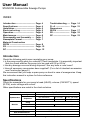
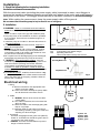
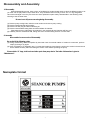
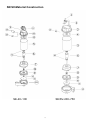
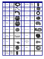
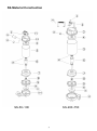
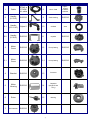
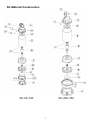
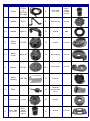
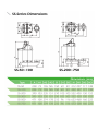
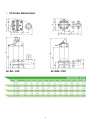
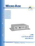
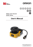
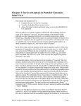
50 HZ
1
INSTRUCTION
This instruction sheet provides you with the information required to safely own and operate your product. Retain these instructions for
future reference.
The product you have purchased is of the highest quality workmanship and material, and has been engineered to give you long and reliable service. This product has been carefully tested, inspected, and packaged to ensure safe delivery and operation. Please examine your
item(s) carefully to ensure that no damage occurred during shipment. If damage has occurred, please contact the place of purchase. They
will assist you in replacement or repair, if required.
READ THESE INSTRUCTIONS CAREFULLY BEFORE ATTEMPTING TO INSTALL, OPERATE, OR SERVICE YOUR
PRODUCT. KNOW THE PRODUCT’S APPLICATION, LIMITATIONS, AND POTENTIAL HAZARDS. PROTECT YOURSELF AND OTHERS BY OBSERVING ALL SAFETY INFORMATION. FAILURE TO COMPLY WITH THESE INSTRUCTIONS COULD RESULT IN PERSONAL INJURY AND/OR PROPERTY DAMAGE!
DESCRIPTION
This pump has been evaluated for use with water only. The motor housing contains a lubrication oil to provide cooling for the motor and
to lubricate bearings and seals. These pumps are capable of operating with the motor housing partially exposed for extended periods of
time, providing sufficient motor cooling and bearing lubrication. However, for the best cooling and longest motor life, the liquid level
being pumped should normally be above the top of the motor housing.
SAFETY GUIDELINES
WARNING : RISK OF ELECTRIC SHOCK.
This pump is supplied with a ground-ing conductor or grounding-type attachment plug. To reduce the risk of electric shock, be certain that
it is connected only to a properly grounded, grounding type receptacle.
When a pump is in a basin, etc., do not touch motor, pipes or water until unit is unplugged or shut off. If your installation has water or
moisture present, do not touch wet area until all power has been turned off. If shut-off box is not acces-sible, call the electric company to
shut off service to the house, or call your local fire department for instructions. Failure to follow this warning can result in fatal electrical
shock.
The flexible jacketed cord assembly mounted to the pump must not be modified in any way, with the exception of shortening the cord to fit
into a control panel. Any splice between the pump and the control panel must be made within a junction box and mounted outside of the
basin, and comply with the National Electrical Code. Do not use the power cord for lifting the pump.
The pump motor is equipped with an automatic resetting thermal protector and may restart unexpectedly. Protector tripping is an indication of motor overload-ing as a result of operating the pump at low heads (low discharge restriction), excessively high or low voltage,
inadequate wiring, incorrect motor connections, or a defective motor or pump.
For a submersible well pump :
Reduced risk of electric shock during operation of this pump requires the provision of acceptable grounding :
When the means of connection to the supply-connection box is other than grounded metal conduit, ground the pump back to the service
by connecting a copper conductor, at lease the size of the circuit conductors supplying the pump, to the grounding screw provided within
the wiring compartment.
This pump is provided with a means for grounding. To reduce the risk of electric shock from contact with adjacent metal parts, bond supply box to the pump-motor-grounding means and to all metal parts accessible at the well head, including metal discharge pipes, metal
well casing, and similar parts, by means of :
An equipment-grounding conductor at lease the size of the well-cable conductors, or the equivalent, that runs down the well with
the well cable and
A clamp, a weld, or both when required, secured to the equipment-grounding lead, the equipment-grounding terminal, or the grounding conductor on the pump housing.
The equipment-grounding lead, when one is provided, is the conductor that has an outer surface of insulation that is green with or without
one or more yellow stripes.
For a cord and plug-connected pump :
Risk of electric shock - This pump is supplied with a grounding conductor and grounding-type attachment plug. To reduce the risk of
electric shock, be certain that it is connected only to a proper grounded, grounding type receptacle.
When use as a fountain pump, to reduce the risk of electric shock, use only on portable self-contained fountains no larger than 5 feet in
any dimension.
Read all instructions and Safety Guidelines thoroughly. Failure to follow the guidelines and instructions could result in serious bodily
injury and/or property damage.
DO NOT USE TO PUMP FLAMMABLE OR EXPLOSIVE FLUIDS SUCH AS GASOLINE, FUEL OIL, KEROSENE, ETC. FAILURE TO FOLLOW THIS WARNING CAN RESULT IN PERSONAL INJURY AND/OR PROPERTY DAMAGE.
2
During normal operation this pump is immersed in water. Also, during rain storms, water may be present in the surrounding area of the
pump. Caution must be used to prevent bodily injury when working near the pump. Electrical power should be disconnected prior to
touching, servicing or repairing the pump.
Do not run the pump in a dry basin. If the pump is run in a dry basin, the surface temperature of the pump will rise to a high level. This
high level could cause skin burns if the pump is touched and will cause serious damage to your pump.
Do not oil the motor. The pump housing is sealed. A high grade dielectric oil devoid of water has been put into the motor housing at the
factory. Use of other oil could cause serious electric shock and/or permanent damage to the pump.
Do not install in locations classified as hazardous in accordance with the National Electrical Code, ANSI/NFPA 70.
Do not remove cord and strain relief. Do no connect conduit to pump.
INSTALLATION
For automatic operation, pump must be plugged or wired into a remote float switch or liquid level controller. Installation instructions are
included with all our switches and controllers and should be referred to for installation. Installation and servicing shall be conducted by
qualified person / people.
Pump will run continuously if plugged directly into an electrical outlet. Care should be taken to prevent pump running in a dry sump.
Pump must be installed with local plumbing codes. Pump must be placed on a hard level surface. Never place pump directly on clay,
earth or gravel surfaces. Pump can be installed with ABS, PVC, polyethylene or galvanized steel pipe. Proper adapters are required to
connect plastic pipe to pump.
Always install a union in the discharge line, just above the sump pit, to allow for easy removal of the pump for cleaning or repair.
A check valve must be used in the discharge line to prevent backflow of liquid into the basin. The check valve should be a free-flow valve
that will easily pass solids.
CAUTION :
For best performance of check valves, when handling solids install in a horizontal position or at an angle of no more than 45°. Do not
install check valve in a vertical position as solids may settle in valve and prevent opening on start-up.
A gate valve should follow the check valve to allow periodic cleaning of the check valve or removal of the pump. The remainder of the
discharge line should be as short as possible with a minimum of turns to minimize friction head loss.
Sewage and effluent applications will require a separate sump vent. A connection is provided on top of the sump or cover which must be
piped to the existing building vent or extended outside with its own standpipe.
WIRING
Check local electrical and building codes before installation. The installation must be in accordance with their regulations as well as the
most recent National Electrical Code (NEC).
Pump should be connected or wired to its own circuit with no other outlets or equipment in the circuit line. Fuses and circuit breaker
should be of ample capacity in the electrical circuit.
MAINTENANCE
If pump does not operate properly or trouble cannot be located, consult your pump dealer or take pump to a STANCOR authorized service center.
CAUTION:
When working on pump or switch, always unplug pump power cord in addition to removing or shutting off circuit breaker before working on pump.
CLEANING IMPELLER AND VOLUTE
WARNING:
DO NOT REMOVE THE HEX. CAP SCREWS. THE MOTOR SECTION OF YOUR PUMP IS PERMANENTLY LUBRICATED
WITH LUBRICATING OIL AND SEALED AT THE FACTORY. REMOVAL OF THESE SCREWS BY ANYONE OTHER THAN
AN AUTHORIZED STANCOR SERVICE CENTER WILL BREAK THIS SEAL AND VOID THE WARRANTY.
Thank you for choose STANCOR Pump
3
User Manual
STANCOR Submersible Sewage Pumps
INDEX
Introduction —————–——-—
Specifications ————–—–—-Installation ————-——-——-Electrical wiring ———–—–—-Operation ———————-——Maintenance ————-—–——-Disassembly and Assembly —Nameplate Format —–——–—-Material Construction
SE/SV ——–——————–——-SS ———————————–—-SC ———————————–—--
Page. 4
Page. 4
Page. 5
Page. 5
Page. 6
Page. 6
Page. 7
Page. 7
Troubleshooting —F.L.A. ——————Dimensions
SE/SV ——–———-SS ———————-SC ———————--
Page. 14
Page. 15
Page. 17
Page. 18
Page. 19
Page. 8
Page. 10
Page. 12
Introduction
Check the following points upon receipting your pump:
> Is the pump exactly what you ordered? Check nameplate. It is especially important
that you check whether the pump is to be used with 50 or 60 Hz.
> Has any damage occurred during shipment? Are any bolts or nuts loose?
> Have all necessary accessories been supplied? (For a list of standard accessories
see Construction page.8 )
We recommend that you keep a spare pump on hand in case of emergencies. Keep
this instruction manual in a place for future reference.
Specifications
Check the nameplate for your pump’s head (HEAD), volume (CAPACITY), speed
(R.P.M), motor voltage and current.
Other specifications are noted in the chart as below.
Item
Specifications
Type
Liquid handled
Temperature
Casing
Impeller
Materials
Sewage, waste water, miscellaneous drain water
Non-Automation
0.4~7.5 HP
0~40℃(32~104F)
Automation
0.4~2 HP
0~40℃(32~104F)
Cast iron / SUS316
Cast iron
Shaft
SUS316 stainless steel (optional)
SUS410 / SUS316 stainless steel
Motor type
Dry type submersible motor
Shaft seal lubrication oil
Turbine No.32 ISO VG-32
Maximum water depth
10m (33ft)
4
Installation
1. Check the following before beginning installation.
Insulation resistance measurement:
With the motor and cable (excluding the power supply cable) immersed in water, use a Megger to
measure the insulation resistance between ground and each phase of the motor, and again between
each phase of the motor. The Megger should indicate an insulation resistance of not less than 20mega
ohms. While making the measurement, keep the power supply cable off the ground .
We recommend that an auxiliary pump be kept on hand in case of emergency.
2. Installation-
on
1.! WARNING : Under no circumstances should cable be
H2
pulled while the pump is being transported or
installed.
Attach a chain or rope to the grip and install the pump.
2.This pump must not be installed on its side or operated
a dry condition. Ensure that it is installed upright on a
secure base.
3. Install the pump at a location in the tank where there is
the least turbulence.
4. If there is a flow of liquid inside the tank, support the
piping where appropriate.
5.Install piping so that air will not be entrapped. If piping
must be installed in such a way that air pockets are
unavoidable, install an air release valve wherever such
air pockets are most likely to develop.
6.Do not permit end of discharge piping to be submerged,
as backflow will result when the pump is shut down.
7..! WARNING : Non-automatic pumps , have an
automatic operating system pump operating water level
near the minimum operating level as the automatic
cut-off switch incorporated inside the motor will be
activated. To avoid dry operation, install an automatic
operating system, as shown in Fig-1 and maintain a safe
operating water level.
8.For automatic pumps , install the floats as shown in Fig2. The pump may not start if a floats switch touches the
wall of the water tank or the piping. Install the floats so
that this will not happen.
H1
off
Fig-1
H1:
H2:
Lowest water level (Motor flange)
Operating water level
This must be above the top of the motor
Operating Water Level
Stop Water Level
Fig-2
Electrical wiring
1.Wiring
A. Wire as indicated for the appropriate start
system as shown in Fig-3.
B. Loose connections will stop the pump. Make
sure all electrical connections secure.
R
S
U
V
Motor
D.O.L.
2. Cable
C. ! WARNING : Never let the end of the cable
contact water.
D. If the cable is extended, do not immerse the
splice in water.
E. Fasten the cable to the discharge piping with
tape or vinyl strips.
F. Install the cable so that it will not overheat.
Overheating caused by coiling the cable and
exposing it to direct sunlight.
3. Grounding
As shown in Fig-4 ground the green wire (label E).
Under no circumstances should the green wire be
connected to the power supply.
4. ! WARNING : Use short circuit breakers to prevent
danger of electrical shock.
T
W
Fig-3
U V W E
Ground
Plate
Fig-4
5
U-phase: red
V-phase: white
W-phase: black
E-phase: green
Operation
1. Before starting the pump
a. After completing installation, measure the insulation resistance again as described in Installation.
b. Check water level.
If the pump is operated continuously for an extended period of time in a dry condition or at the lowest water
level, the motor protector will be activated. Constant repetition of this action will shorten pump service life.
Do not start the pump again in such a situation until after the motor has completely cooled.
2. Test operation….
Non-automatic pump
Automatic pump
a. Turn the operating switch on and off a couple of times to check for normal pump start.
Floating switch must be raised for the pump to start.
b. Next, check direction of rotation. If discharge volume is low or unusual sounds are heard when the pump is
operating, rotation has been reversed. When this happens, reverse two of the wires.
Maintenance
Check pressure, output, voltage, current and other specifications. Unusual readings may indicate. Refer to Troubleshooting and
correct as soon as possible.
1. Daily inspections
Check current and ammeter fluctuation daily. If ammeter fluctuation is great, even though within the limits of pump rating,
foreign matter may be clogging the pump. If the quantity of liquid discharged falls suddenly, foreign matter may be
blocking the suction inlet.
2. Regular inspections
a. Monthly inspections
Measure the insulation resistance. The value should be more than 1M ohm. If resistance starts to fall rapidly even
with an initial indication of over 1M ohm, this may be an indication of trouble and repair work is required.
b. Annual inspections
To prolong the service life of the mechanical seal by replacing the oil in the mechanical seal chamber once a
year. Water mixed the oil or cloudy textures are indications of a defective mechanical seal requiring replacement.
When replacing the oil, lay the pump on its side with filler plug on top. Inject suitable amount turbine oil No.32
(ISO VG-32)
.
c. Inspections at 3-5year intervals
Conduct an overhaul of the pump. These intervals will preclude the possibility of future trouble.
3. Parts that will need to be replaced
Replace the appropriate part when the following conditions are apparent.
Replaceable part
Mechanical seal
Whenever oil in
Replacement guide mechanical seal
chamber is clouded
Frequency
Annually
Oil filler plug gasket
Lubricating oil
O-ring
Whenever oil is replaced
or inspected
Whenever clouded or dirty
Whenever pump is
overhauled
A half yearly
A half yearly
Annually
Note: above replacement schedule is based on normal operating conditions.
Motor output
0.4HP
0.5HP
Mechanical seal
Oil seal
Oil filler plug gasket
Lubricating oil
(turbine oil #32)
1HP
2HP
3HP
5HP
7.5HP
12Ø
19.875(3/4”)Ø
25Ø
12Øx 24Øx 7 t
18Øx 35Øx 7 t
25Øx 47Øx 8 t
(Inner diameter) x (outer diameter) x (thickness)
120 cc
220cc
=8.5Øx 13Øx 0.8 t PE washer
500 cc
6
600 cc
Disassembly and Assembly
1. DisassemblyWhen disassembling pump, have a piece of cardboard or wooden board ready to place the different parts on as
you work. Do not pile parts on top of each other. They should be laid out neatly in rows. The “O” ring and gasket
cannot be used again once they are removed. Have replacement parts ready. Disassemble in the following order,
referring to the sectional view.
! ! WARNING : Be sure to cut off power source beginning disassembly.
(1) Remove pump casing bolts, raise the motor section and remove pump casing.
(2) Remove shaft head bolt and impeller.
(3) Remove oil filler plug and drain lubricating oil.
(4) Remove intermediate casing bolts and intermediate oil chamber.
(Remember that any lubricating oil remaining in the mechanical seal chamber will flow out.)
(5) Carefully remove mechanical seal, taking care not to scratch sliding surface or motor shaft.
2. AssemblyRe-assemble in reverse order of disassembly.
Be careful of the following points.
(1) During re-assembly, rotate the impeller by hand and check for smooth rotation. If rotation is not smooth, perform
steps-(3) through -(5) again.
(2) Upon completion of re-assembly step -(1) rotate the impeller by hand from the suction the suction inlet and check
that it rotates smoothly without touching the suction cover before operating the pump.
Please obtain “O” rings, shaft seals and other parts from pump dealer. The table of dimensions is given in
“Maintenance”.
Nameplate format
7
SE/SV-Material Construction
SE-40~100
SE/SV-200~750
8
NO.
Name
Material
1
Photo
NO
Name
Material
Cable
STOW
or
STJOW
UL cable
8
Mech. Seal
(5~7.5HP)
Upper :
CA/CE
LOWER:
SIC/SIC
2
Handle
SS41
9
Seal Housing
FC-200
2-1
Handle
Nylon 6
10
Oil Seal
NBR
3
Motor
Cover
FC-200
11
Impeller
FC-200
3-1
Motor
Cover
Nylon 66
12
Pump Casing
FC-200
4
Bracket
FC-200
12-1
Pump Casing
FC-200
5
Motor
Housing
SUS-304
13
Protector
6
Rotor
14
Capacitor
(Single Phase
Only)
7
Oil Chamber
FC-200
15
Bearing
8
Mech.
Seal
(0.4~3HP)
Upper :
CA/CE
LOWER:
CA/CE
9
Photo
SS-Material Construction
SS-50~100
SS-200~750
10
NO.
Name
Material
1
Cable
STOW or
STJOW
UL cable
2
Handle
(5~7HP)
2-1
Photo
NO
Name
Material
8
Mech. Seal
Upper :
CA/CE
LOWER:
SIC/SIC
SUS316
9
Seal Housing
SUS316
Handle
(0.5~1HP)
Nylon 6
10
Oil Seal
Viton
2-2
Handle
(2~3HP)
SUS316
11
Impeller
SUS316
3
Motor
Cover
SUS316
12
Pump Casing
SUS316
3-1
Motor
Cover
SUS316
12-1
Pump Casing
SUS316
4
Bracket
SUS316
13
Protector
5
Motor
Housing
SUS316
14
Capacitor
(Single Phase
Only)
6
Rotor
15
Bearing
7
Oil Chamber
SUS316
11
Photo
SC-Material Construction
SC-50~100
SC-200~750
12
NO.
Name
Material
1
Photo
NO
Name
Material
Cable
STOW
or
STJOW
UL cable
8
Mech. Seal
(5~7.5HP)
Upper :
CA/CE
LOWER:
SIC/SIC
2
Handle
SS41
9
Seal Housing
FC-200
2-1
Handle
Nylon 6
10
Oil Seal
NBR
3
Motor
Cover
FC-200
11
Impeller
FCD-450
3-1
Motor
Cover
Nylon 66
12
Pump Casing
FC-200
4
Bracket
FC-200
12-1
Pump Casing
FC-200
5
Motor
Housing
SUS-304
13
Protector
6
Rotor
14
Capacitor
(Single Phase
Only)
7
Oil Chamber
FC-200
15
Bearing
8
Mech. Seal
(0.4~3HP)
Upper :
CA/CE
LOWER:
CA/CE
16
Strainer
13
FCD-450
Photo
Troubleshooting
Trouble
Cause
Remedy
Does not start. Starts, but
immediately stops.
(2) Large discrepancy between power source and voltage
(1) Power failure
(1)~(3) Contact electric power company and devise counter-measures
(3) Significant drop in voltage
(4) Motor phase malfunction
(4) Inspect electric circuit
(5) Electric circuit connection faulty
(5) Correct wiring
(6) Faulty connection of control circuit
(6) Inspect connections and magnetic switch
(7) Fuse blown
(7) Replace with correct type of fuse
(8) Faulty magnetic switch
(8) Replace with correct one
(9) Water is not at level indicated by Float
(9) Raise water level
(10) Float is not in appropriate level
(10) Adjust the position of float
(11) Float effective
(11) Repair or replace
(12) Short circuit breaker is functioning
(12) Repair location of short circuit
(13) Foreign matter clogging pump
(13) Remove foreign matter
(14) Motor burned out
(14) Repair or replace
(15) Motor bearing broken
(15) Repair or replace
Operates, but stops after (1) Prolonged dry operation has activated motor protector
and caused pump to stop
a while.
Does not pump. Inadequate volume.
Over current
(1) Raise stop water level
(2) High liquid temperature has activated motor protector
and caused pump to stop
(3) Reverse rotation ! WARNING :
(1) Reverse rotation
(2) Lower liquid temperature
(2) Significant drop in voltage
(3) Operating a 60Hz pump on 50Hz
(2) Contact electric power company and devise
counter-measures
(3) Check nameplate
(4) Discharge head is high
(4) Recalculate and adjust
(5) Large piping loss
(5) Recalculate and adjust
(6) Low operating water level causes air suction
(6) Raise water level or lower pump
(7) Leaking from discharge piping
(7) Inspect, repair
(8) Clogging of discharge piping
(8) Remove foreign matter
(9) Foreign matter in suction inlet
(9) Remove foreign matter
(10) Foreign matter clogging pump
(10) Remove foreign matter
(11) Worn impeller
(11) Replace impeller
(1) Unbalanced current and voltage
(3) Motor phase malfunction
(1) Contact electric power company and devise
counter-measure
(2) Contact electric power company and devise
counter-measure
(3) Inspect connections and magnetic switch
(4) Operating 50Hz pump on 60Hz
(4) Check nameplate
(5) Reverse rotation ! WARNING :
(5) Replace pump with low head pump
(6) Low head. Excessive volume of water
(6) Remove foreign matter
(7) Foreign matter clogging pump
(8) Motor bearing is worn or damaged.
(7) Motor bearing is worn or damaged
(7) Replace bearing
(2) Significant voltage drop
Pump vibrates; excessive
operating noise.
(2) Pump clogged with foreign matter
(3) Correct rotation
(1) Correct rotation (see Operation)
(1) Correct rotation
(2) Disassemble and remove foreign matter
(3) Piping resonates
(3) Improve piping
(4) Gate valve is closed too far
(4) Open gate valve
14
F.L.A
Phase
Model
Item
HP
Voltage
HZ
Amp
1
3
ν
110V
0.5HP
8
ν
4
ν
2
ν
ν
ν
50HZ
ν
12
ν
6
ν
3
ν
ν
ν
ν
2HP
11.3
ν
6
50HZ
ν
ν
50HZ
ν
ν
ν
5HP
50HZ
ν
ν
ν
7.5HP
50HZ
ν
ν
SC-50A
0.5HP
SC-200A
2HP
8
ν
ν
1HP
12
50HZ
ν
SC-100A
12
ν
ν
8.6
21
ν
ν
ν
8.6
ν
ν
5.7
15
ν
SC-750
5.2
ν
ν
3.3
9
ν
SC-500
3.5
ν
ν
SC
3HP
1.8
ν
ν
SC-300
1.8
ν
ν
SC-200
1
ν
ν
1HP
415V
50HZ
ν
SC-100
380V
ν
ν
SC-50
230V
ν
4
12
50HZ
50HZ
ν
ν
6
ν
ν
11.3
15
Phase
Model
Item
HP
Amp
1
SE-40
0.4HP
Voltage
HZ
50HZ
3
ν
0.5HP
50HZ
230V
ν
4.6
2.3
ν
ν
8
ν
4
ν
2
ν
ν
ν
50HZ
ν
12
ν
6
ν
3
ν
ν
ν
2HP
ν
50HZ
11.3
ν
6
ν
ν
SE/SV/SS-300
3HP
50HZ
ν
ν
ν
5HP
ν
ν
50HZ
ν
7.5HP
50HZ
ν
ν
0.4HP
50HZ
SE/SS-50A
0.5HP
50HZ
SE/SV/SS-100A
1HP
50HZ
SE/SV/SS-200A
2HP
50HZ
ν
ν
ν
ν
2.3
8
ν
ν
12
4.6
ν
ν
12
ν
ν
8.6
21
ν
ν
SE-40A
8.6
ν
ν
5.7
15
ν
SE/SV/SS-750
5.2
ν
ν
3.3
9
ν
SE/SV/SS-500
3.5
ν
ν
1.8
ν
ν
SE/SV/SS
1.8
ν
ν
SE/SV/SS-200
1.2
ν
ν
1HP
415V
ν
ν
SE/SV/SS-100
380V
ν
ν
SE/SS-50
110V
ν
4
12
ν
ν
6
ν
ν
11.3
16
17
18
19
STANCOR, INC., 515 Fan Hill Rd,. Monroe, CT
06468
Phone : (203) 268-7513
Fax : (203) 268-7958
http://stancorpumps.com
20