1
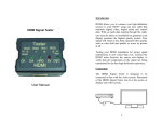
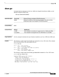
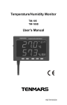
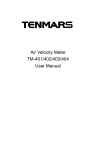
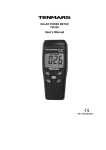
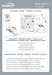
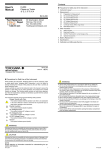
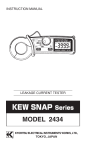
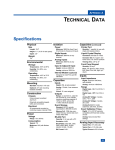
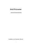
MILLIOHM METER
TM-508A
User’s Manual
HB2TM508A000
CONTENTS
Features...........................................................................................................4
1
General specifications ..............................................................................4
2
Instrument description ..............................................................................5
3
Notice in prior to the testing ......................................................................6
4
Electrical specifications:............................................................................6
5
Measurement by the Four Wire type one pair of coated clip.....................7
6
Precise Impedance measurement ............................................................8
7
Battery Replacement ................................................................................9
8
Replacement of fuse.................................................................................9
9
Maintenance and Care ...........................................................................10
10
END OF LIFE ..................................................................................10
TM-508A
Features
1. Very low impedance measurement by Four Wire type one pair coated
clip.
2. There is a fuse (0.5A/250V) to pro the input circuit.
3. Applicable measurement of Resistance, motor coil, transformer, Printed
Circuit Board.
4. Accurate measurement of conductor, light electricity and welding
point.
5. Wide measurement range, 0.1 mΩ to 20kΩ in 6 positions.
6. D – H Switch: Lockup readings for LCD display.
1 General specifications
1. Display:
2.
3.
4.
5.
6.
7.
Overload indication:
Zero Adjust:
Low battery indication:
Reading speed:
Operating attitude:
Operating ambience:
8.
Operating temperature
and R.H. value:
9. Storage temperature and
R.H. value:
10. Power supply:
11. AC adapter:
12. Dimension and weight:
13. Accessories:
14. Fuse specification:
3-1/2 digits, LCD display with max. reading of
1999 with decimal point and measurement
unit.
“OL” indication.
External zero adjust knob.
Replace battery as LCD display “
”
2.5 times per second.
Max. 2000 meters above level.
In-door use, under environmental pollution
grades two.
5°C to 40°C, 80%RH or lower.
-10°C to 60°C, 70%RH or lower.
1.5V × 6 NEDA 15F IEC R6 JIS SUM-3
AC input Voltage is 100Vac to 240Vac 0.3A
with input frequency of 60 HZ or 50HZ,Free
Voltage DC output is 9VDC(8~11VDCMax)
Supply current:>0.5ADC. Socket:pin Ground
Casing Positive External Diameter 3.5mm
internal Diameter 2.0mm
160 x 100 x 52mm. approximate 500g.
One set of testing clips and instruction
manual.
0.5A/250V, 5Øx 20mm. FAST MIN
INTERRUPTS RATINGS 1500A.
EN-4
TM-508A
2 Instrument description
1. RX socket:
For testing clips input.
2. LCD display:
Indication of measured value and unit.
3. ZERO ADJ. Knob:
For zero adjustment.
4. Power switch and
Selection in functional range of the meter.
Range selector switch:
5. D-H:
Lock up the LCD reading.
6. DC Power socket:
For AC adapter output DC Voltage is
9VDC(8~11VDCMax).
FIG (1)
EN-5
TM-508A
3
Notice in prior to the testing
1. Don not connect the testing input terminals LO, RX, RX, HI,) any
input voltage directly, so as to prevent any possible damage to the
internal circuits of the meter.
4
Electrical specifications:
( 23°C±5°C, 80% RH or lower )
Accuracy :
Range
±( ……….% reading + ……… digit):
200 mΩ
0.1mΩ
Testing
current
100mA
2Ω
1mΩ
10mA
10mΩ
10mA
200Ω
0.1Ω
1mA
2kΩ
1Ω
1mA
20kΩ
10Ω
100uA
20Ω
Accuracy
±(0.3%+ 4dgt)
Resolution
EN-6
Open Voltage
Approx. 4.8VDC
TM-508A
5
Measurement by the Four Wire type one pair of coated clip
To guarantee an higher precise measurement of this digital Ohmmeter,
an accurate wide range impedance testing equipment, and to eliminate
any Improper Influence of measurement, especially in effect of the
impedance of testing leads, the following procedures should be
followed.
1.
2.
3.
4.
5.
FIG(2)
Please refer to the table shown above, a testing current is passed in
individual testing range (from HI end to the LO end).
The specific electric current flows through any unknown resistance
RX.
The Voltage VX can be measured on RX1, RX2 terminals,
VX = RX x IS therefore
RX = VX / IS
The unknown resistance value can be given on LCD display from VX
voltage value to be measured.
To obtain accurate impedance measured without any resistance
value impedance between terminals RX1 and RX2.
EN-7
TM-508A
6 Precise Impedance measurement
1. Insert an RED testing lead into “HI” socket and another RED testing lead
into the adjacent “RX” socket; insert a BLACK testing lead into “LO”
socket and another BLACK testing lead into the adjacent “RX” socket,
2.
Select the function switch to 200 mΩ position.
3.
Short circuit the two testing clips, adjust “ ZERO ADJUST KNOB” (3-5) to
a” 000” reading value on the LCD.
4.
Whenever a selected range of 200 mΩ ,2Ω ,20Ω , 200Ω to be measured
the readjustment of “ZERO ADJST” shall be deeply necessary.
5.
To measure an unknown resistor RX then by following the two point type
of measurement per shown in figure 3.
6.
7.
FIG(3)
Measure the resistance on PCB by using the two-point type of
measurement per shown in figure 4.
FIG(4)
The measured value is shown on LCD .
EN-8
TM-508A
7 Battery Replacement
The meter is powered by 1.5V battery x6pcs (NEDA 15F IEC R6 JIS UM-3).
Use the following procedure to replace the battery:
1. Replace battery immediately when LCD displays “ ”.
2. Turn the function switch to the "OFF" position.
3. Use a screwdriver to unfasten the screws on the battery cover and
remove the cover.
4. Take out the old batteries and replace with new batteries, taking care to
note the correct polarity.
5. Re-install the battery cover and tighten the holding screws.
8 Replacement of fuse
For a safety protection of the electrical circuit please replace new fuse
complying the specification 0.5A/250V, 5Øx 20mm. FAST MIN INTERRUPT
RATINGS 1500A.
1.
2.
3.
Select the function range switch to “OFF” position. To unscrew the bottom
case by using a screwdriver.
Pull out the burned fuse and replace a new one.
Close the bottom case and tighten screw.
EN-9
TM-508A
9
Maintenance and Care
1. That all necessary requirements of inspection and maintenance are not
mentioned in this manual, a qualified technician should perform it.
2. This meter is a precision digital instrument, whether in use or in storage,
please do not exceed the specification requirements to avoid any
possible damage or danger during use.
3. Do not use strong or abrasive detergents, water and wet cloth to clean
the instrument. Do use a dry cloth to clean the instrument.
4. Do not place this meter in high temperature or humidity or expose to
direct sunlight.
5. Once the measurement is completed, turn the rotary switch to OFF,
Remove the batteries from battery holder if the instrument is not is used
for a long period in order to avoid the liquid leakage from the battery.
10 END OF LIFE
Caution: this symbol indicates that equipment and its accessories
shall be subject to a separate collection and correct disposal
EN-10
TENMARS ELECTRONICS CO., LTD
6F, 586, RUI GUANG ROAD, NEIHU,
TAIPEI 114, TAIWAN.
E-mail: [email protected]
http://www.tenmars.com