1
Integrated 2D CAD system for additional annotation
of GGU application graphics
MINI-CAD
HEADER CAD
VERSION 7
Last revision:
March 2010
Copyright:
Prof. Dr. Johann Buß
Technical implementation and sales: Civilserve GmbH, Steinfeld
Contents:
1 About the Mini-CAD system............................................................................................... 4
1.1 Mini-CAD and Header CAD............................................................................................ 4
1.2 Activating the Mini-CAD system..................................................................................... 4
1.3 Activating the Mini-CAD functions................................................................................. 5
2 Short description of individual icons.................................................................................. 6
3 Mini-CAD system preferences ............................................................................................ 7
3.1 General notes on preferences ........................................................................................... 7
3.2 General "Info" preferences............................................................................................... 7
3.3 Layer preferences ............................................................................................................. 8
3.3.1 Drawing and selection layers................................................................................... 8
3.3.2 Layer operations ...................................................................................................... 9
3.4 Array preferences ........................................................................................................... 10
3.5 Capturing line ends ........................................................................................................ 10
3.6 Defining fonts................................................................................................................. 10
3.7 Pen preferences and pen selection.................................................................................. 11
4 Creating/inserting Mini-CAD objects .............................................................................. 12
4.1 Line objects (lines, polygons, rectangles, circles, Bezier splines) ................................. 12
4.2 Generating a normal ....................................................................................................... 12
4.3 Texts............................................................................................................................... 13
4.4 Graphics ......................................................................................................................... 14
4.5 DXF import .................................................................................................................... 15
4.5.1 Importing DXF data............................................................................................... 15
4.5.2 Scaling DXF data................................................................................................... 16
4.6 Tables ............................................................................................................................. 17
4.6.1 Start tables function ............................................................................................... 17
4.6.2 Enter base data....................................................................................................... 17
4.6.3 Enter column headings........................................................................................... 18
4.6.4 Enter table values................................................................................................... 19
4.7 Diagrams ........................................................................................................................ 20
4.8 Special functions ............................................................................................................ 21
4.8.1 Selection ................................................................................................................ 21
4.8.2 North arrow............................................................................................................ 21
4.8.3 Reference staff ....................................................................................................... 22
4.8.4 Foundation ............................................................................................................. 23
5 Editing Mini-CAD objects................................................................................................. 23
5.1 Editing with the editor box............................................................................................. 23
5.1.1 General editing notes ............................................................................................. 23
5.1.2 Editor box for a line............................................................................................... 24
5.1.3 Editor box for a rectancle or a circle...................................................................... 25
5.1.4 Editor box for a text............................................................................................... 26
5.1.5 Editor box for a polygon........................................................................................ 27
5.2 Set as default/Use default............................................................................................... 28
5.3 Convert to polygon......................................................................................................... 28
5.4 Mark objects................................................................................................................... 29
Mini-CAD User Manual
Page 2 of 42
March 2010
5.5 Modify objects ............................................................................................................... 30
5.6 Edit styles ....................................................................................................................... 31
5.7 Trim lines ....................................................................................................................... 32
5.7.1 Trim two lines........................................................................................................ 32
5.7.2 Trim lines on an object .......................................................................................... 33
5.8 Break lines...................................................................................................................... 34
5.9 Move nodes .................................................................................................................... 35
6 Displacing/moving Mini-CAD objects.............................................................................. 36
6.1 Displacing with the mouse ............................................................................................. 36
6.2 Displacing via editor ...................................................................................................... 36
6.3 Changing sequence of visualisation ............................................................................... 37
6.3.1 Move individual objects ........................................................................................ 37
6.3.2 Move all objects on a layer .................................................................................... 37
6.3.3 Changing the sequence of Mini-CAD objects/program graphics .......................... 38
6.4 Changing layer allocations ............................................................................................. 38
7 Deleting/saving/loading Mini-CAD objects ..................................................................... 39
7.1 Deleting Mini-CAD objects ........................................................................................... 39
7.2 Saving Mini-CAD objects.............................................................................................. 39
7.3 Loading Mini-CAD objects............................................................................................ 40
8 Keyboard commands......................................................................................................... 40
9 Index.................................................................................................................................... 41
Mini-CAD User Manual
Page 3 of 42
March 2010
1 About the Mini-CAD system
1.1
Mini-CAD and Header CAD
An integrated CAD system is included in all GGU programs, allowing your GGU program
graphics to be supplemented with texts, characters or graphics objects.
In some GGU applications you can choose between "Mini-CAD" and "Header CAD" functions.
These two CAD systems can be thus differentiated:
• Drawing objects created with "Mini-CAD" are with reference to the drawing coordinate
system (generally in [m]) and are displayed accordingly. You should therefore only select
this menu item if you need to add additional information to the system.
• Drawing objects created with "Header CAD" are with reference to the page format (in
[mm]). They therefore always remain at the same position on the page, regardless of the
coordinates of the system. You should always use this menu item when entering general
information (e.g. company logo, report number, appendix number, stamp). When you save
these so-called header data, they can be reloaded into a completely different system (with
different system coordinates). This header data will therefore always appear at the same
position. This greatly simplifies the generation of general page information.
1.2
Activating the Mini-CAD system
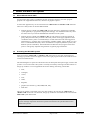
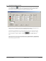
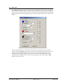
After selecting the "Mini-CAD" or "Header CAD" menu item in your GGU application a socalled pop-up window with icons appears in the lower right program window; the CAD functions
can be activated from here.
The same dialogue box opens for both menu items; all subsequent descriptions apply to both CAD
systems. You can see which CAD system is currently activated by referring to the blue title bar in
the pop-up window. You can supplement the current drawing with freely positionable
• lines;
• rectangles;
• circles;
• texts;
• tables;
• diagrams;
• graphics (file formats e.g. JPG, BMP, PSP, TIF);
• DXF files.
The pop-up window is moveable, just as any other window. By selecting the "Mini-CAD" or
"Header CAD" menu item a second time, the pop-up window is removed from the screen and the
Mini-CAD system deactivated.
All preferences and operations described below are only active within the current CAD
system. Settings required for both CAD systems must therefore be specified and saved in
both CAD systems.
Mini-CAD User Manual
Page 4 of 42
March 2010
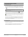
1.3
Activating the Mini-CAD functions
Information on each function can be seen if the mouse pointer is placed over a Mini-CAD toolbar
icon without pressing the mouse button.
In order to activate the respective function you must first select the object to be drawn (line, circle,
rectangle, text, graphics, etc.) with a mouse click on the corresponding icon. Activated icons are
displayed inverted.
The actual drawing process is initiated by concurrently pressing the [Shift] key and the left mouse
button. The [Shift] key can then be released. Alternatively, the "CAD without shift key" can also
be activated. You can then add Mini-CAD objects without simultaneously pressing the [Shift]
key.
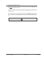
The "CAD without Shift" icon is activated by default when the program starts,
recognisable by its inverted appearance
Mini-CAD User Manual
.
Page 5 of 42
March 2010
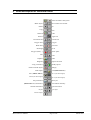
2 Short description of individual icons
Deactivate Mini-CAD system
Mark objects
Delete
Move node/Create normal
Cut
Copy
Paste
Mark all
Undo
Restore
Horizontal line
Polygon lines
Break lines
Rectangle
Polygon (filled, ...)
Single line
Vertical line
Polygon
Trim lines
Circle
Bezier spline
Text
Fonts
Graphics
Table
Diagrams
Capture line ends
Array preferences
Rotate selected objects
DXF import
Modify objects
Multiply
Load (Mini-CAD file)
Save (Mini-CAD file)
Pen 1 (as current pen)
Pen 2 (as current pen)
Pen 3 (as current pen)
Pen preferences
(Mini-CAD tools) Preferences
General information
Layers
Edit styles
CAD without shift key
Special functions
Up a layer
Down a layer
Mini-CAD User Manual
Page 6 of 42
March 2010
3 Mini-CAD system preferences
3.1
General notes on preferences
You can apply preferences to a variety of tools in advance of working with the Mini-CAD system.
These preferences remain active throughout the complete session, even if you deactivate the MiniCAD system in the meantime. After leaving the program and restarting, the Mini-CAD system
default preferences are activated once again.
"Preferences"
You can alter the column number of the Mini-CAD window or deactivate the Mini-CAD system
using the "Off" button.
"CAD without shift key"
If you need to draw a number of Mini-CAD objects you can simplify the task by activating this
tool. You can then add new objects without simultaneously pressing the [Shift] key.
"Info"
You will see some general information. Furthermore, you can select preferences for status bar
display and some general display options (see Section 3.2).
"Layers"
You can work on 20 layers in the Mini-CAD systems. Using this icon you may select between
drawing and selection layer and perform various operations on the objects in selected layers (see
Section 3.3).
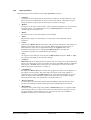
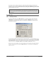
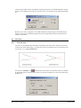
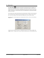
3.2
General "Info" preferences
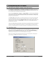
A dialogue box opens allowing you to define the information to be displayed in the Mini-CAD
module status bar.
If you have copied objects the new objects are pasted at the same location by default. If the "Move
objects slightly after paste" check box is activated the copied objects can be more easily
recognised by slightly offsetting them and thus be marked for moving, for example.
The remaining objects are partially smeared when the moved objects are pulled across them. In
order to see all objects correctly again after moving, activate the check box "Refresh screen after
moving".
Symbols, which can be imported from a file with the ".syb" extension, can be used to fill polygons
. If the symbol file is saved using the default name "MiniCadSymbols.syb" it is automatically
loaded when the program starts. The file is first searched for in the program folder, then at the
working level and finally in the Windows folder. If the symbols are also to be used in other GGU
programs it makes sense to save the symbol file in the Windows folder. To open a new symbol file
click the corresponding button and select the file from the file selector box. Symbols can be
created using the GGU mbH freeware program SymbolDef and saved in a symbol file. More
complex symbols can be created using the GGU mbH freeware program GGUMiniCAD and then
integrated into your symbol file.
Mini-CAD User Manual
Page 7 of 42
March 2010
The preferences specified in the "Info" dialogue box can be saved in either the ".ggu_mcd_ini"
file or the ".ggu_kpf_ini" file. If these files are saved in the program folder (default) the
preferences will be automatically loaded the next time the program is started.
In addition, you can view the total number of Mini-CAD objects present in this icon's dialogue
box by pressing the "Statistics" button. Detailed statistics including the number of objects on the
individual layers are shown in the "Layers" icon dialogue box (see Section 3.3).
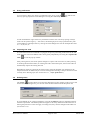
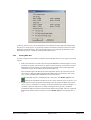
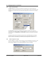
3.3
3.3.1
Layer preferences
Drawing and selection layers
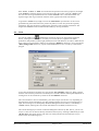
Define preferences according to your requirements for working on the various layers. After
clicking the "Layers" icon the following dialogue box opens:
All subsequent objects are drawn on the layer selected as "Current drawing layer". Objects
pasted from the clipboard are also inserted in the selected drawing layer.
Objects on the layer defined as the "Current selection layer" can be selected and moved using
the left mouse button or by opening the object editor using the right mouse button. It may make
sense to define a certain selection layer, if a number of objects are closely spaced or overlap and
are therefore difficult to mark using the mouse.
The current drawing and selection layers are displayed in the program's status bar:
= drawing layer 2/selection layer 1.
By activating the "Selection layer = drawing layer" check box, the selection layer is
automatically adjusted when changing to the next higher or lower drawing layer. This can be done
very quickly using the "Up one layer"
Mini-CAD User Manual
and "Down one layer"
Page 8 of 42
icons.
March 2010
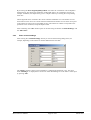
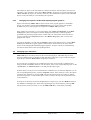
3.3.2
Layer operations
The following options are available in the "Layer operations" group box:
• "Statistics"
A dialogue box opens displaying the total number of objects in the individual layers. The
buttons of layers containing objects are active and can be clicked. A message box opens
listing the objects by object type and the respective number of each type.
• "Reduce"
The objects on all layers can be moved to a layer selected in a dialogue box. This operation
cannot be undone. You should therefore save your Mini-CAD data to a file before
commencing (see also Section 7.2).
• "Delete"
All objects on one or more selected layers can be deleted.
• "Select"
Selected object types on a selected layer or on all layers can be marked for certain
operations.
• "Load"
Objects from a Mini-CAD file of the same CAD type can be loaded into a selected layer in
addition to the existing objects. If you click the "New" button, the existing objects are
deleted from this layer; they are supplemented using the "Append" button. Any
distribution among the layers in the appended Mini-CAD file is not taken into
consideration; all objects are loaded into the selected layer.
• "Save"
All objects of a selected layer can be saved to a Mini-CAD file using the ".mcd" or ".kpf"
file extension, depending on the selected CAD type.
• "Sequence"
Mini-CAD objects are displayed in the sequence they were created in. Using this button all
objects in a selected layer can be moved either in front of ("To front" button) or behind all
other objects ("To back" button). All objects in a selected layer can also be moved to a
different layer (also see Sections 6.3.2 and 6.4).
• "Visualisation"
By default, the Mini-CAD objects used in GGU programs are drawn over the graphics of
the respective GGU program. This means that some regions of the result graphics or
legends may be covered by the Mini-CAD objects. In this button's dialogue box you can
choose to display objects behind the graphics of the respective GGU program. Simply
deactivate the check box for required layer (see also Section 6.3.3).
• "Reverse selection"
If certain object types have been marked suing the "Select" button, the selection can be
quickly reversed using this button and the previously unmarked objects be selected.
• "Hide/unhide"
To improve clarity when using a large number of Mini-CAD objects it is possible to hide
selected drawing layers. To do this, remove the ticks in the boxes for the respective layer.
Using the buttons in the dialogue box's lower group box all layers can be hidden or
unhidden simultaneously, or a selection reversed.
Mini-CAD User Manual
Page 9 of 42
March 2010
3.4
Array preferences
You can insert or draw your objects on a defined x and y array. Click the
icon and activate
the array spacing input boxes in the dialogue box using the "Use array" check box.
You do not define the origin of the array with the first mouse click. The array spacing is always
relative to the system origin x/y = 0/0. That is, the drawing object is always positioned at a point
corresponding to a multiple of the x/y value given in the dialogue box. For the example above that
is x = 10, 20, 30, etc.
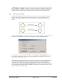
3.5
Capturing line ends
If several lines need to be connected to a polygon, the precise positioning of the mouse at the end
of the previous line can be difficult. This can be greatly simplified by activating the "Capture line
ends"
tool in the pop-up window.
After pressing this too, the mouse pointer changes to a square with cross-hairs. If, when pressing
or releasing the left mouse button, an existing line end is within the square, the new line end will
automatically capture the existing line end.
Depending on the layer selected as the selection layer using the "Layers" icon preferences, the
end points of lines on different layers can also be snapped to: Drawing is always carried out on the
currently active drawing layer (also see Section 3.3.1, "Layer preferences").
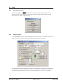
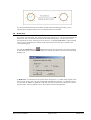
3.6
Defining fonts
The "Fonts"
function allows to use any font desired for text. By clicking on this tool you will
see the following dialogue box; you can now select the desired font from the drop-down list.
If you would like to use a font not listed here, press the "Load new" button to supplement the list
with the required font. The defined preference applies to all newly defined texts from the time of
altering the preference. It does not apply to existing texts; they must be changed in the editor box
(see Section 5.1.4).
Mini-CAD User Manual
Page 10 of 42
March 2010
3.7
Pen preferences and pen selection
Using "Edit pens 1,2,3"
the width, colour and type of line representation can be predefined.
You can choose between a variety of line types including dimension lines, ground lines, slope
lines, hatch lines, grass lines, arrowed lines, or height or groundwater symbols.
The pen colour can be altered by clicking the corresponding button with the pen designation. The
current pen colour is used as the text colour when adding text to the drawing.
At the bottom of the dialogue box it is possible to define the current pen in a drop-down list box.
Selection of a default pen for use with the subsequent drawing functions is achieved by clicking
the corresponding icon "Pen 1", "Pen 2" or "Pen 3"
menu.
in the Mini-CAD pop-up
The pen preferences can be saved to a file with the extension ".ggu_mcd_std" or ".ggu_kpf_std".
If these files are saved in the program folder (default) the preferences will be automatically loaded
the next time the program is started.
Mini-CAD User Manual
Page 11 of 42
March 2010
4 Creating/inserting Mini-CAD objects
4.1
Line objects (lines, polygons, rectangles, circles, Bezier splines)
For "Single line", "Horizontal line", "Vertical line", "Rectangle" and "Circle" click the start
point with the left mouse button and move to the end point holding the mouse button down. The
line is then drawn after releasing the left mouse button.
When creating "Polygon lines", "Polygon" or "Polygon (filled, ...)", the start point is defined by
pressing the left mouse button. By pressing the left mouse button once again you define the end
point of the line, which is then also the start point of the next line. The function is completed by
pressing the right mouse button.
The "Bezier spline" function allows you to draw any kind of curve. Four points are required for
this, which are defined by mouse click using the left mouse button. In order to attach a Bezier
spline to an existing one, activate the "Capture line ends" function before starting to draw. Each
individual spline is treated as a "Polygon (filled, ...)" and can be correspondingly edited, e.g.
provided with a colour fill.
Colour, pen width, dashing or selecting a certain line type (e.g. dimension line) can be selected in
advance by activating a predefined pen (see Section 3.7). When editing an existing line object
open the corresponding editor box by double-clicking the corresponding object (see Section 5.1).
4.2
Generating a normal
Lines can be generated at a user-defined angle (called the normal here for simplicity) to existing
lines or edges of existing Mini-CAD system objects. Activate the "Move nodes/generate
normal" icon and click the object to be edited. The nodes of the selected object are displayed.
These are the two end points of a line or the defined points of a polygon.
If the line is clicked with the right mouse button between two polygon points, a dialogue box
opens allowing a normal to the clicked line to be generated:
Mini-CAD User Manual
Page 12 of 42
March 2010
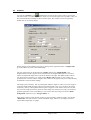
If the "Start", "Centre" or "End" are activated as the position in the lower group box, the length
of the normal to be drawn must be given in the group box above this. Using the "Angle" input
box lines can also be generated that are not classical normals at 90° to the selected line. If a
negative angle value is given the line is drawn on the opposite side of the selected line.
To generate a normal of any length, activate the "With mouse" option button. A line can be
generated using the mouse and can be position anywhere, even far away from the originally
clicked line. The new line always remains in the extension of the originally clicked line. The
length of the normal can also be defined individually by moving the mouse.
4.3
Texts
Activate the "Text" icon
and define the position of new text by pressing the left mouse
button. A dialogue box then opens, in which you can enter the text, together with further
preferences (left justified, centred, right justified, font size and direction). In order to make the text
more visible you can generate a frame by activating the "With box" check box. If you activate the
"Delete background" check box, objects situated behind the text are covered by a white-filled
polygon.
To use these preferences for further text, activate the "Set as default" check box. When you then
enter the next text these preferences will already be activated as default. Subsequent adjustment of
existing texts can be carried out by means of the "Use default" check box.
The colour used for a new text is defined by your choice of pen (see Section 3.7). Depending on
the preferences for the selected pen it is thus possible to display text in a given colour directly at
input. If an existing text is subsequently edited the dialogue box shown above is extended by a
"Colour" button, allowing the colour of the selected text to be edited (see Section 5.1.4).
The current drawing layer is shown in the blue dialogue box title bar by '#1'. That is, you are now
in layer 1. New text can also be directly inserted in other layers by selecting a different layer in the
"Do not move" drop-down list box. The new text is then placed in the selected layer but you
remain in the current drawing layer.
Mini-CAD User Manual
Page 13 of 42
March 2010
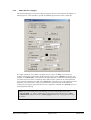
4.4
Graphics
Activate the "Graphics" icon
and define the position of the top left corner by pressing the
left mouse button. A window opens from which you can load an image from any folder. Once you
have selected the desired image an editor window opens; this window can also be opened by
double-click on an existing image.
Further images can be loaded at any time by clicking on the uppermost button. "Graphics info"
gives the number of pixels in the loaded image.
The size of the image can be altered using "Width" and the ratio "Height/Width". The
height/width ratio of the original can be read off below the height/width input box. In order to
import an undistorted image click on the "Use" button to the right. The default width is always
5.0, which often represents a very small value in Mini-CAD (in metres in your system). It is
probably better to set the width to a higher value, otherwise the graphics may be so small that they
are difficult to click for further editing.
The image can be rotated by 180° by entering the width as a negative value. If you enter negative
values for height/width the image will be mirrored around the x axis. You can mirror the image
around the y axis by entering both of these inputs as negative values. Please note, however, that
any text in the image will also be mirrored. These image must either be previously processed in a
graphics application or the text hidden by a new text box after mirroring (activate the "Delete
background" function) or by a "Polygon (filled, ...)".
If the image contains a large amount of white, it may be useful to frame the image. Activate the
"With frame" check box to draw a frame around the image. Moreover, the image can also be
represented transparently or opaque.
Mini-CAD User Manual
Page 14 of 42
March 2010
If you need to insert a number of images, the width setting and the settings for the frame and
transparency can be used for the following images by clicking "Set as default". In contrast to new
text input, graphics are always inserted in the current drawing layer, which is displayed in the blue
title bar of the editor box by '#1'.
If the file contains integrated graphics only the filename with complete path will be saved.
If you are working with a file with integrated graphics the graphics file must thus always be
saved with it.
4.5
4.5.1
DXF import
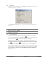
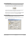
Importing DXF data
If you have already drawn some Mini-CAD objects, you must now decide, after selecting the
"DXF import" icon, whether the DXF data are to be added ("Additional" button) or first the
existing objects be deleted ("New" button). You will then see a dialogue box in which you can
define import preferences.
If you encounter problems when importing fonts from the DXF file, e.g. special characters are not
correctly represented, you may be able to achieve better results by deactivating the "Texts in DXF
file in OEM format" check box or by applying a font size factor. If colour fill does not need to be
imported, activate the "Command "TRACE" and "SOLID" without fill" check box.
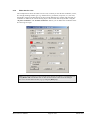
When you now click on "OK" you can select the DXF file to be imported. The program interprets
the DXF commands and converts them to Mini-CAD objects. You will then see a dialogue box
similar to this one:
Mini-CAD User Manual
Page 15 of 42
March 2010
At the top of this box you can see information on the dimensions of the DXF file and the image
data for your current project. It is generally useful to activate the lower three check boxes in the
dialogue box (default setting). The program then ensures a screen-filling representation of the
DXF data and you see a summary of the imported DXF objects.
4.5.2
Scaling DXF data
In order to adjust the scale and the coordinates of the DXF data to that of your project proceed as
follows:
• Find a horizontal and a vertical line in the imported DXF data of known lengths. You can
also draw an auxiliary line between two points of known spacing. Click the line icon and
then double-click the auxiliary line with the left mouse button. The actual length of the
clicked line is given on the title bar of the opened editor box.
If the required length is divided by the actual length the result is the zoom factor for the
size correction. Because differing heights and widths result from zooming to full screen
size, you also get differing horizontal and vertical zoom factors.
To adapt the DXF objects to the defined project scale select the "Modify objects" icon
and enter the calculated zoom factors for the x and y directions (also see Section 5.5).
• Displacements can also be generated in analogy to this to position the DXF import at the
correct x and y coordinates. For example, in the first step find a line of known height (= y
coordinate). Open the editor box by double-clicking the line to get the y coordinate.
Calculate the difference between the theoretical and the actual height, which is required as
displacement. Ensure that the zoom factor in the "Modify objects" icon dialogue box is
1.0.
Mini-CAD User Manual
Page 16 of 42
March 2010
4.6
4.6.1
Tables
Start tables function
Activate the "Table" icon
and define the position of the table by pressing the left mouse
button. A selection window opens in which you can define the table appearance and enter the
desired values in a series of dialogue boxes.
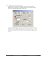
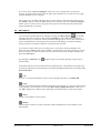
4.6.2
Enter base data
Use the "Base data" button to enter the designation, position, font sizes, row heights, colours and
number of rows and columns. The following dialogue box appears, for example:
Any designation entered is displayed in a header line in the table. If no designation is entered this
row is absent from the table. A different font size to the remainder of the table can be used for the
designation. The position of the table can be precisely defined using "x" and "y" coordinates.
Mini-CAD User Manual
Page 17 of 42
March 2010
By activating the "Row height depth-dependent" check box the visualisation can be adapted to
the depth scale. This allows the parameters of individual strata to be visualised in sections, for
example. In addition, the depth can be given in a depth column by activating the corresponding
check box.
The background can be coloured in the various columns and header rows. The number of rows
and columns can be varied. In a strata-oriented visualisation the number of rows must correspond
to the number of strata in the corresponding section. The number of columns corresponds to the
parameters to be visualised, except the depth column.
After confirming with "OK" further inputs can be done using the buttons "Column headings" and
the "Edit values".
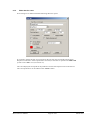
4.6.3
Enter column headings
After clicking the "Column headings" button you will see the following dialogue box, for
example, depending on the number of columns defined in the base data:
The "Depth" column is always present whether it is subsequently displayed or not. The input
under "Heading 2" is displayed in a second row within the heading row in the table. Use the input
by pressing "OK".
Mini-CAD User Manual
Page 18 of 42
March 2010
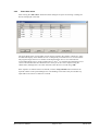
4.6.4
Enter table values
After clicking the "Edit values" button the follow dialogue box opens for entering or editing the
data to be displayed in the table.
The strata depths of the corresponding section must be entered in the "Depth" column for a strataoriented table display. If the number of rows is subsequently increased a new row is inserted here.
The program assigns the new row number as the depth and the new row is inserted into the
corresponding depth section. In the example above a new 5th row would be inserted between rows
1 and 2. Once the data has been edited the rows can be put in the correct sequence using the
"Sort" button, although this is also done automatic when the box is closed using "OK".
If the sequence of columns needs to be altered, click the "Swap columns" button and enter the
required columns in the opened dialogue box. The headings can be left as they are and thus any
input made in the incorrect column be corrected.
Mini-CAD User Manual
Page 19 of 42
March 2010
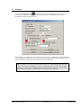
4.7
Diagrams
Activate the "Diagram" icon
and define the position of the diagram by pressing the left
mouse button. The following window opens to enable input of the diagram name, value
designations, font sizes, annotation, etc.
Depending on the visualisation selected in the menu (bar, line, x/y graph), the corresponding input
boxes and buttons required are current. When the lower buttons are clicked further dialogue boxes
open to allow input of graph colours, dimensions and measured data.
Tip: To delete a value once it has been entered allocate it a fictitious depth larger than that
of any other value (or the highest y value for x-y diagrams). Then sort the values by depth
(or by the y values for an x-y diagram) and reduce the number of values by one. The value
with the maximum depth (or the maximum y value) has now been deleted.
Mini-CAD User Manual
Page 20 of 42
March 2010
4.8
4.8.1
Special functions
Selection
Using the "Special functions" icon
you can have a selection of objects represented without
having to draw them yourself. The following dialogue box opens allowing selection of the
required object:
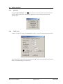
4.8.2
North arrow
To draw a North arrow, select the "North arrow" button; you will see the following dialogue box:
After entering the required data and confirming with "OK", draw a line along the North-South line
and you will automatically get a North arrow.
Mini-CAD User Manual
Page 21 of 42
March 2010
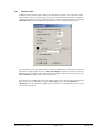
4.8.3
Reference staff
In addition to the reference staffs used by some of the GGU programs you can also have further
vertical reference lines represented, e.g. if you have a number of sections at differing heights or
you need to use this function to generate horizontal or otherwise oriented scale bars. Click on the
"Reference staff" button and enter the required values into the subsequent dialogue box.
If you then draw a line, the program creates a reference staff from this, which always begins and
ends with a complete length unit. The "With original heights" check box is always activated by
default for vertical reference staffs. The actual section heights of the started GGU program (e.g.
GGU-STRATIG) are then used for the reference staff.
If you need a section-independent, vertical reference staff, you can deactivate this check box and
define a start point for the staff by using the "Offset [m]" function. If "User-defined" or
"Horizontal" are selected from the staff type list, the check box is automatically inactive and you
can work with the offset.
Mini-CAD User Manual
Page 22 of 42
March 2010
4.8.4
Foundation
To represent a standard foundation click on "Foundation", enter the foundation dimensions into
the dialogue box and draw the footing base.
The "Foundation" function remains active, allowing you to draw a number of foundations in
succession.
5 Editing Mini-CAD objects
5.1
5.1.1
Editing with the editor box
General editing notes
By double-clicking on objects with the left mouse button a dialogue box opens, allowing the
function is activated, the editor box
object to be individually edited. If the "Mark objects"
opens when you press the right mouse button above the corresponding object.
Only objects on the current selection layer can be selected. If you have specified a special
selection layer using the "Layers" icon and not all layers, you must first change to the drawing
layer which is also defined as selection layer. This can be done very quickly using the "Up one
layer"
and "Down one layer"
icons (also see Section 3.3.2 "Layer preferences").
Objects that directly open an editor box for new input (e.g. texts, tables, etc.) also open the editor
box again if the object is double-clicked. However, the box is now supplemented by a "Delete"
button and a number of other functions (e.g. "Set as default", "Use default", "Do not move"
drop-down combo box). These functions are described in more detail in separate sections (see
Sections 5.2 and 6.3.1).
Mini-CAD User Manual
Page 23 of 42
March 2010
5.1.2
Editor box for a line
The example below shows the editor box for a line, in which you can edit the coordinates, colour,
line strength, dashing and line type (e.g. dimension line, ground line, slope line, etc.). For lines,
the length is shown in the blue title bar at the top of the dialogue box, together with the angle of
inclination. In addition, the current drawing layer is shown in the title bar by the '#1'. Using the
"In polar coordinates" and "In delta coordinates" buttons you can define the coordinates of the
line from a given origin.
TIP: If you want to measure a certain length in the drawing, first draw a corresponding line
using Mini-CAD. Then double-click on this line and read the values from the dialogue
box. You can then delete the line (e.g. by using the [Back] key).
Mini-CAD User Manual
Page 24 of 42
March 2010
5.1.3
Editor box for a rectancle or a circle
The editor box for a rectangle is shown below. The circle editor box is identical, the only
difference being that instead of the x/y coordinates of the opposing corners of the rectangle you
will see the x/y coordinates of the circle centre and the radius.
The pen colour, width and dashing correspond to the preferences for the pen selected to draw the
rectangle or circle. If the "Fill" check box is activated, the rectangle or the circle is drawn with a
colour fill, which can be defined via the "Colour" button. The outline of the rectangle or circle is
always drawn in black if the colour fill is activated. Only the pen width and the dashing can then
be altered.
Mini-CAD User Manual
Page 25 of 42
March 2010
5.1.4
Editor box for a text
If an existing text is double-clicked the following editor box opens:
If you need to change the font of an existing text the new font can be selected from the upper
drop-down combo box. If the required font is not listed, it must first be opened in the Mini-CAD
system via the "Font" icon (see Section 3.6).
The colour displayed corresponds to the preferences for the selected pen used to create the text.
The colour preferences can be edited via the "Colour" button.
Mini-CAD User Manual
Page 26 of 42
March 2010
5.1.5
Editor box for a polygon
The following dialogue box opens for editing a polygon. The box is the same for an unfilled or a
filled polygon. It is thus possible to provide an unfilled polygon with a colour or hatch fill.
If a ".syb" symbol file was opened at program start-up or later via "Info" (see Section 3.2),
symbols from this file can be used to fill the selected polygon in the "Hatching" group box. For
example, if "Symbols (fill)" is selected from the upper drop-down combo box, the subsequent fill
covers the entire area. In the second drop-down combo box the symbol can be selected from the
list of symbols available in the ".syb" file ("Stonework" in the above box). The symbol fill can be
adapted to your requirements via the pen width and size. Symbol fill can be aborted before
complete by pressing the right mouse button. If no ".syb" file is available the "Symbols" choice is
not displayed for hatching.
TIP: If you want to hide parts of the drawing, cover the corresponding region with a
"Polygon (filled, ...)". After a double-click on the polygon, assign the fill colour "white",
"without hatch" and deactivate the "Frame polygon" check box. The polygon then acts as
an 'eraser'.
Mini-CAD User Manual
Page 27 of 42
March 2010
5.2
Set as default/Use default
If you have already drawn an object you can use the preferences for this object as the default
values for subsequent, similar objects. To do this, open the editor dialogue box for this object by
double-clicking the object. Then activate the "Set as default" check box and leave the dialogue
box using "OK". When using the "Text" and "Graphics" functions the preferences can be saved
as the default for further objects of this type immediately upon the first input or first insertion.
If a number of previously drawn objects need to be adapted to a default setting, the preferences are
first applied to one object and then set as default (see above). The editor dialogue boxes of the
other objects can then be opened and the "Use default" check boxes activated.
Subsequent adaptations of several objects of differing types can also be carried out using the "Edit
styles" function (see Section 5.6). However, colour or hatch fill for "Polygon (filled,...)" objects
can only be edited directly in the object editor or via "Set as default"/"Use default".
5.3
Convert to polygon
The line objects "Rectangle" and "Circle" can be subsequently converted to polygons, in order to
adapt the figures using the "Move nodes" icon, for example (see Section 5.9).
First, draw the desired object and then open the editor dialogue box with a double-click over the
objekt; here, as an example, is the box for a circle:
Mini-CAD User Manual
Page 28 of 42
March 2010
If you click on the "Convert to polygon" button, the circle is automatically converted to a
polygon. To further edit the object open the editor with a double-click over the circle once again
to get the dialogue box for a polygon.
If the polygon is to be filled with the current pen colour (shown in the little coloured box next to
the "Colour" button), activate the "Fill" check box first and then click the "Convert to polygon"
button. Upon conversion, the new polygon will be given the selected colour fill and the object
edging automatically set to black.
5.4
Mark objects
You can select individual objects for editing by selecting the "Mark objects"
tool and then
clicking on the object in question. By pressing the [Shift] key and simultaneously clicking on
individual objects, several objects can be selected for editing at once. You can also select several
objects simultaneously by pressing the left mouse button and drawing a rectangle around the
objects in question. All objects within this rectangle are thus selected.
It is possible to select object types on certain layers or on all layers using the "Layers" icon.
Simply click the "Select" button in the "Layers" icon dialogue box and select the object type and
layer (or all layers) on which the objects are to be selected. Circles and rectangles belong to the
object type line objects.
By clicking the "Mark all" icon
then be edited.
all drawn objects are selected regardless of type and can
The marked objects can also be edited with the normal functions. The preferences and operations
are then only applied to the selected objects. The following additional functions are available only
for marked objects:
"Cut"
You can cut out the marked objects, open a new file and paste the objects via Mini-CAD.
"Copy"
You can copy the marked objects and then paste them to the same file, or a new file. When pasting
to the same file it can be useful to activate the "Move objects slightly after paste" check box in
the "Info" dialogue box, otherwise the copied objects are pasted exactly on top of the original.
"Paste"
Cutted or copied objects can be pasted.
"Rotate"
Marked objects (with the exception of graphics, tables and diagrams) can be rotated by a userdefined angle.
Mini-CAD User Manual
Page 29 of 42
March 2010
"Multiply"
The marked objects can be duplicated in the specified number. You can define a spacing in x and
y direction for the new objects.
"Edit styles"
You can modify the line colours, for example, in one step for several marked objects (see Section
5.6 for details).
5.5
Modify objects
The "Modify objects "
tool allows object sizes to be modified or objects to be displaced by
defined distances. If objects have been previously marked the command applies to the selected
objects only, otherwise all objects on all layers are modified. After clicking the icon the following
dialogue box opens. The blue title bar indicates that the operation only applies to the selected
objects.
You can use the zoom factor to enlarge or reduce objects. The zoom centre can be in the centre of
the selected objects or at a point specified by the user (activate "Around fixed point with x and
y"). Zooming can even be limited to a given direction (x or y coordinates), selected in "Apply to:"
. If you only need to modify font sizes, select "None" here. If you need to retain the font size when
zooming, deactivate the "Use zoom factor on fonts" check box.
By entering values in "Displacement", you can move objects in metres of the current scale in x
and/or y direction. Ensure that any previously adopted zoom factor is set back to 1.0 for the
displacement.
Mini-CAD User Manual
Page 30 of 42
March 2010
5.6
Edit styles
The "Edit styles" function is only available if you have marked one or more objects. The marked
objects can all be modified together, e.g. all line objects and all text objects can be represented in a
given colour. The group boxes for line objects, text objects and polygons displayed in the dialogue
box only appear if the corresponding object types are marked, otherwise those areas of the box are
hidden.
After activating the respective "Use" check boxes the desired modifications can be entered or
selected. In the "Line objects" group box the colour fill of colour-filled rectangles and circles can
be edited using the "Colour" button. The pen colour for colour-filled rectangles and circles is
black and cannot be altered. The line pen colour for normal lines and unfilled objects can be
changed using the "Colour" button. The colour fill of polygons cannot be altered using "Edit
styles" (see also Section 5.2).
Mini-CAD User Manual
Page 31 of 42
March 2010
Colour and pen width can also be edited by selecting the objects to be modified and then clicking
on the icon of a different pen to the one currently in use. You will then see the following dialogue
box:
However, lines, texts or polygons are not differentiated; the changes apply to all marked objects.
The new colour of colour-filled rectangles and circles is adopted for the colour fill and the new
width for the outlines.
5.7
5.7.1
Trim lines
Trim two lines
Two lines can be automatically extended or shortened to their intersection. The lines need not be
located on the same drawing layer, you need only to have activated all layers as the selection layer
(see Section 3.3.1, "Layer preferences").
and then click on the lines to be trimmed. The first is marked
Activate the "Trim lines" tool
by little black squares at the line ends. When you click the second line you will see the following
dialogue box:
Mini-CAD User Manual
Page 32 of 42
March 2010
If "Both lines" are clicked, the lines are united, i.e. extended or shortened as shown in the sketch
above. If "Line 1" or "Line 2" are selected, only the respective line is extended or shorted to the
imaginary intersection. Where crossing lines need to be shortened, the shortest individual line
ends will always be trimmed The line numbers refer to the sequence when clicking the lines.
5.7.2
Trim lines on an object
Beside trimming two lines, it is also possible to trim lines on a circle, a rectangle or a polygon.
This provides exact line attachments to the respective object. It is possible for this type of
trimming to trim the lines inside or outside of your object, as demonstrated in the following
sketch.
Activate the "Trim lines" icon and click the object first, i.e. circle, rectangle or polygon. Second,
click the line to be trimmed. For a circle, for example, the following dialogue box opens:
Select external or internal trim and click "OK". If the "Continue to show dialogue box" check
box is left activated a further line can be clicked immediately after trimming the first one; the
marked object then remains selected.
The "All" button in the dialogue box may also be used. All lines that intersect the marked object
(here a circle) are trimmed internally or externally depending on the selection made above,
without the need to click every line. Before carrying out this operation a further dialogue box
opens allowing the "Also delete ALL lines within Circle" check box to be activated. If the check
box is activated lines inside the object are deleted even if they do not intersect its outline. This is
demonstrated in the following sketch.
Mini-CAD User Manual
Page 33 of 42
March 2010
For the situation demonstrated in the sketch and the selected trimming procedure, you are
informed upon completion that 3 lines were deleted and 9 lines trimmed.
5.8
Break lines
If two lines cross each other, they can be broken at the intersection, i.e. the lines are divided at the
intersection. The lines need not be located on the same drawing layer, you need only to have
activated all layers as the selection layer (see Section 3.3.1,"Layer preferences"). After breaking
a line a piece of the broken line remains on the selection layer, the other part is pasted to the
current drawing layer.
and then click on the lines to be broken. The first is marked
Activate the "Break lines" tool
by little black squares at the line ends. When you click the second line you will see the following
dialogue box:
If "Both lines" is clicked the lines are broken at the intersection, i.e. instead of the original 2 lines
there are now 4 lines. They can now be displayed with different properties, e.g. different colours
or pen widths. If "Line 1" or "Line 2" is selected, only the respective line is broken into 2 lines at
the intersection. The line numbers refer to the sequence when clicking the lines.
Mini-CAD User Manual
Page 34 of 42
March 2010
5.9
Move nodes
The "Move nodes"
function allows the shape of an existing object (line, rectangle, circle,
polygon, Bezier spline) to be altered. Activate the icon and click the object to be edited. The
movable nodes on the selected object are displayed as small, black, square points. On a line, for
example, these are the two end points and the defined polygon points in a polygon. If the mouse
pointer is located above a node its pointer forms a cross and the point can be moved by holding
the left mouse button.
If an existing node is right-clicked a dialogue box displaying the coordinates of the clicked point
opens. The object type is displayed in the blue dialogue box title bar, together with the object's
layer. The node coordinates can be edited in the dialogue box by direct numerical input.
The number of the clicked polygon point is displayed in the title bar, as shown in the following
dialogue box:
A further option available for polygons is changing the polygon course using the "Insert" and
"Delete" buttons. A polygon point is always inserted centrally between 2 existing polygon points.
Mini-CAD User Manual
Page 35 of 42
March 2010
6 Displacing/moving Mini-CAD objects
6.1
Displacing with the mouse
You can displace a single object by means of the right mouse button. A prerequisite for this is
that the icon for the appropriate object type is clicked and the object is located on the selection
layer. Position the mouse over the object and move it to the desired position with the right mouse
button pressed. This action can be undone by pressing the [Back] key or by clicking the "Undo"
icon
.
Direct displacement with the right mouse button is not possible for polygons, Bezier
splines, tables and diagrams.
Alternatively, objects can also be moved by marking ("Mark objects"
icon is activated) and
subsequently moving them using the left mouse button. Several objects can be marked using the
[Shift] key and the left mouse button or open a window on the required objects by holding the left
mouse button. All drawn objects are selected regardless of type by clicking the "Mark all" icon
. If objects of a certain type need to be marked, press the "Select" button in the "Layers" icon
dialogue box (also see Section 5.4).
After marking your objects (regardless of how) move them to their new positions by holding the
left mouse button. To move a marked object only horizontally, hold the X key and move the
marked objects using the left mouse button. The mouse pointer turns into a left-right pointer. If
objects only need to be moved vertically, hold the Y key and move using the left mouse button.
The mouse pointer turns into an up-down pointer.
6.2
Displacing via editor
In general, displacement of objects by direct modification of the object coordinates is possible. For
example, double-click over the object to be moved to open the corresponding editor dialogue box
(see Sections 4.1 pp. and Section 5.1).
If you need to move several objects at once by a fixed amount, select the objects to be moved and
then click on the "Modify objects" icon. In the dialogue box you can then specify the
displacement in metres in the current scale for the x and/or y direction (see Section 5.5).
Mini-CAD User Manual
Page 36 of 42
March 2010
6.3
6.3.1
Changing sequence of visualisation
Move individual objects
The Mini-CAD objects are drawn in the sequence in which they were created. If objects are
(partially) covered by objects drawn later, you can alter the sequence of object representation. This
is achieved via a list in the lower region of the editor dialogue boxes, shown here for an example
rectangle.
The "Do not move" preference is the default setting and does not influence the sequence of
representation. With "Move to back" and "Move to front" the object is moved to the foremost or
rearmost position. Using "Backwards" and "Forwards" the object is moved back or forwards by
one position.
The sequence always refers to the objects on one layer only. If individual objects on one layer
need to be drawn in front of objects on a different layer, these objects must be placed on empty
layers (see Section 6.4) and these layers then moved to the foreground (see Section 6.3.2).
6.3.2
Move all objects on a layer
Using the "Layers" it is possible to move all objects in a layer simultaneously to the back or to the
front in the visualisation sequence. Click the "Sequence" button in the dialogue box that opens
after clicking the "Layers" icon. The following dialogue box opens, for example:
Mini-CAD User Manual
Page 37 of 42
March 2010
The number of objects in the selected layer is shown in brackets. If all the objects on a layer are
selected it is only possible to move them "Move to back" (all objects are moved to the back) and
"Move to front" (all objects are moved to the front). The visualisation sequence of the individual
objects on the selected layer is not altered by this operation.
6.3.3
Changing the sequence of Mini-CAD objects/program graphics
Objects inserted using Mini-CAD are drawn in front of the program graphics in the default
setting. It is therefore possible that the Mini-CAD objects cover parts of the main graphics.
Problems may occur when graphics are integrated via Mini-CAD in particular.
If the graphics are imported, e.g. a site map bitmap, click "Show as transparent" in the MiniCAD graphics editor. The image will then be displayed transparently so that the graphics
generated using the main program remain visible. There are some printer drivers that do not
correctly reproduce the transparent function. The Mini-CAD graphics then cover the main
graphics after output.
Activate the "Layers" icon and click the "Display" button in the dialogue box to position MiniCAD objects behind the program graphics. Deactivate the check boxes for the layers whose
objects are to be displayed behind the program graphics. All layers can also be simultaneously
activated or deactivated via the corresponding buttons.
6.4
Changing layer allocations
Mini-CAD objects are always drawn on the current drawing layer. Individual objects can be
moved to a different layer by double-clicking the object's editor box to open it and selecting the
required layer from the "Do not move" drop-down combo box.
If several objects are marked (even on different layers) they can be moved to a different layer
using the "Cut" and "Paste" functions. Cut the objects, move to the required drawing layer via the
"Up one layer" or "Down one layer" icons and paste the object again.
If all the objects on a layer are to be transferred to a different layer, activate the "Layers" icon. In
the corresponding dialogue box, click the "Sequence" button. Select the layer to move the objects
to and start the operation by pressing "OK". The movement between layers cannot be undone,
unless the target layer is void of other objects. Then, of course, this step can be performed in the
reverse direction.
If all objects on all layers need to be amalgamated on a single layer, click the "Reduce" button in
the "Layers" icon dialogue box. Select the required target layer and confirm by pressing "OK".
This operation is also irreversible, so save the Mini-CAD data to a file before proceeding.
Mini-CAD User Manual
Page 38 of 42
March 2010
7 Deleting/saving/loading Mini-CAD objects
7.1
Deleting Mini-CAD objects
The last-drawn object can be deleted by means of the "Undo"
key. Deleted objects can be recovered using the "Restore"
icon or by pressing the [Back]
icon.
Individual objects are deleted by selecting them with the mouse and then pressing the [Del] key. A
prerequisite for this is that the icon for the appropriate object type is clicked. You can also open
the editor boxes of individual objects and click the respective "Delete" button.
You can delete one or more objects simultaneously with the [Del] key, after previously selecting
them with the "Mark objects" function. Also available is the "Delete"
icon. Using this
option you can delete all Mini-CAD objects concurrently (after a confirmation prompt). If you
have previously marked objects, only those marked objects will be deleted with the "Delete" icon,
but without prompting.
If all objects on a selected layer are to be deleted, activate the "Layers" icon. Click the "Delete"
button in the corresponding dialogue box and select the layer to be deleted. Only those layers
containing Mini-CAD objects are actively displayed. If objects on a layer are accidentally deleted
the operation can be restored using the "Undo" icon.
7.2
Saving Mini-CAD objects
In all GGU software applications the Mini-CAD objects are saved with the current record. If you
want to save objects separately in order to load them into different GGU programs or into a
different record of the same program, you can do this after selecting the "Save" icon
.
The files generated using "Mini-CAD" are automatically awarded the ".mcd" file
extension. Mini-CAD files generated using "Header CAD" are automatically awarded the
".kpf" file extension.
If you have selected objects before with "Mark objects", only these marked objects will be saved.
All objects on individual layers can also be saved separately. Activate the "Layers" icon. Click the
"Save" button in the corresponding dialogue box and select the required layer.
If you have integrated a "Graphics" into the record, only the filename with complete path will be
saved. During a "DXF import" the DXF data are converted to Mini-CAD objects; the original
DXF file is then no longer required.
Mini-CAD User Manual
Page 39 of 42
March 2010
7.3
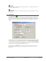
Loading Mini-CAD objects
You can open an existing Mini-CAD file at any time during your project session by using the
"Load"
defined.
icon. A dialogue box opens allowing preferences for the type of data transfer to be
All objects contained within the new file can be imported to the current drawing layer, which is
shown in brackets. If the objects are distributed among different layers in the new file, they layer
allocations can be accepted by activating the option box. If objects are already present in your
program, you may decide whether the existing objects should be deleted ("New" button) or
retained ("Append" button).
A Mini-CAD file can also be imported directly to a selected layer. Activate the "Layers" icon and
click the "Load" button in the corresponding dialogue box. The required layer can be selected
from the drop-down combo box; any existing objects are given in brackets following the
corresponding layer. In this way a previously unoccupied layer can be selected without effort. If a
layer is selected that already contains objects, the subsequent choice of button, "New" or
"Append", is important, because the existing objects on the selected layer are deleted if "New" is
chosen. Any distribution among the layers in the appended Mini-CAD file is not taken into
consideration when importing to a layer; all objects are imported to the selected layer.
If you have integrated a "Graphics" into the record, only the filename with complete path will be
saved. Therefore, if you use such a record on a different computer, the same graphics file must be
saved on that computer using the same path. If this is not the case, the user is requested to enter
the new path when loading the record.
8 Keyboard commands
[Back]
undoes the last action.
[Del]
deletes the objects at the mouse pointer or the selected objects with the drawing function activated.
Mini-CAD User Manual
Page 40 of 42
March 2010
9 Index
A
M
Array, define for Mini-CAD............................. 10
Mini-CAD file, import to selected layer........... 40
Mini-CAD file, load to selected layer................. 9
Mini-CAD file, save ......................................... 39
Mini-CAD functions, activate ............................ 5
Mini-CAD layers,
change visualisation sequence...................... 37
Mini-CAD layers, delete................................... 39
Mini-CAD layers, display in status bar .............. 8
Mini-CAD layers, hide/unhide ........................... 9
Mini-CAD layers, move all objects .................. 38
Mini-CAD layers, reduce to one layer................ 9
Mini-CAD layers, save ..................................... 39
Mini-CAD object types, edit subsequently....... 31
Mini-CAD object types, select ..................... 9, 29
Mini-CAD objects, change outline ................... 35
Mini-CAD objects, copy with offset................... 7
Mini-CAD objects, cut/copy/paste ................... 29
Mini-CAD objects, delete................................. 39
Mini-CAD objects, displace via
numerical input ............................................ 36
Mini-CAD objects, displace with mouse .......... 36
Mini-CAD objects, display behind
program graphics...................................... 9, 38
Mini-CAD objects, draw without shift key......... 5
Mini-CAD objects, edit individual objects
subsequently................................................. 23
Mini-CAD objects, edit marked objects
subsequently................................................. 31
Mini-CAD objects, enlarge/reduce ................... 30
Mini-CAD objects, load ................................... 40
Mini-CAD objects, move to different layer...... 38
Mini-CAD objects, rotate ................................. 29
Mini-CAD objects, save ................................... 39
Mini-CAD objects, save one layer to a file ........ 9
Mini-CAD pens, save/load preferences ............ 11
Mini-CAD status bar, settings ............................ 7
Mini-CAD system, activate ................................ 4
Mini-CAD system, differences ........................... 4
Mini-CAD system, make default settings........... 7
Mini-CAD system, save/load default settings .... 8
B
Bar charts, define via Mini-CAD...................... 20
Bezier spline, define in Mini-CAD................... 12
Bezier spline, edit in Mini-CAD....................... 35
C
CAD without shift key........................................ 5
Circle, convert to polygon ................................ 28
Circle, define in Mini-CAD.............................. 12
Circle, edit in Mini-CAD.................................. 25
Colour fill, define for Mini-CAD polygon ....... 27
Colour fill, define for rectangle/circle in
Mini-CAD .................................................... 25
D
Defaults, specify/use for
Mini-CAD object types ................................ 28
Defaults, specify/use for Mini-CAD system....... 8
Depth column, activate in Mini-CAD table...... 18
Diagram, define via Mini-CAD........................ 20
Display sequence, change for
Mini-CAD layers............................................ 9
Drawing layer, define ......................................... 8
DXF data, import to Mini-CAD ....................... 15
DXF data, scale in Mini-CAD .......................... 16
F
Font, change for Mini-CAD texts ..................... 26
Font, select default for Mini-CAD texts ........... 10
Footing, create via Mini-CAD.......................... 23
G
Graphics, integrate via Mini-CAD ................... 14
Graphics, rotate ................................................ 14
H
Hatch fill, define for Mini-CAD polygon......... 27
N
Normal, generate to Mini-CAD objects............ 12
North arrow, create via Mini-CAD................... 21
P
L
Line graph, define via Mini-CAD .................... 20
Lines, break in Mini-CAD................................ 34
Lines, define in Mini-CAD............................... 12
Lines, edit in Mini-CAD................................... 24
Lines, trim in Mini-CAD .................................. 32
Mini-CAD User Manual
Pens in Min-CAD, edit for lines ....................... 24
Pens in Mini-CAD, default settings.................. 11
Pens in Mini-CAD, edit for polygons............... 27
Pens in Mini-CAD, edit for rectangle/circle ..... 25
Pens, change for Mini-CAD text ...................... 26
Polygon, add/delete points in Mini-CAD ......... 35
Polygon, define in Mini-CAD .......................... 12
Polygon, edit in Mini-CAD .............................. 27
Page 41 of 42
March 2010
R
Rectangle, convert to polygon .......................... 28
Rectangle, define in Mini-CAD........................ 12
Rectangle, edit in Mini-CAD............................ 25
Reference staff, create via Mini-CAD .............. 22
S
Selection layer, define ........................................ 8
Snap radius, activate for line end points ........... 10
Statistics, Mini-CAD objects in layers ............... 9
Statistics, of all Mini-CAD objects..................... 8
Status bar Mini-CAD, settings............................ 7
Symbol file, open for polygon filling ................. 7
Symbols, select for polygon filling................... 27
T
Table in Mini-CAD, enter column headings..... 18
Table in Mini-CAD, enter data......................... 19
Table in Mini-CAD, swap columns .................. 19
Table, define via Mini-CAD............................. 17
Text in Mini-CAD, define ................................ 13
Text, edit in Mini-CAD .................................... 26
Trim, lines on an object .................................... 33
Trim, two lines.................................................. 32
V
Visualisation sequence, change for
individual Mini-CAD objects....................... 37
Visualisation sequence, change for
Mini-CAD layers.......................................... 37
X
x/y graph, define via Mini-CAD....................... 20
Table in Mini-CAD, define rows/columns ....... 17
Mini-CAD User Manual
Page 42 of 42
March 2010