1
Analysis of foundation settlements to DIN 4019
GGU-SETTLE
VERSION 4
Last revision:
August 2014
Prof. Dr. Johann Buß
Copyright:
Technical implementation and sales: Civilserve GmbH, Steinfeld
Contents:
1 Preface .................................................................................................................................. 7
2 Capabilities........................................................................................................................... 8
3 Licence protection and installation .................................................................................... 9
4 Language selection............................................................................................................... 9
5 Starting the program ......................................................................................................... 10
6 Short introduction using worked examples..................................................................... 11
6.1 Program concept............................................................................................................. 11
6.2 Analysis of rectangular foundations............................................................................... 11
6.2.1 System data ............................................................................................................ 11
6.2.2 Define soils ............................................................................................................ 13
6.2.3 Define default layer depths .................................................................................... 14
6.2.4 Define triangle nodes ............................................................................................. 15
6.2.5 Adjust layer depths of nodes.................................................................................. 16
6.2.6 Define triangle mesh.............................................................................................. 16
6.2.7 Define rectangular foundations.............................................................................. 17
6.2.8 Check input data .................................................................................................... 18
6.2.9 Specify limiting depth............................................................................................ 19
6.2.10 Specify type of settlement analysis........................................................................ 20
6.2.11 Calculate foundation settlements ........................................................................... 22
6.2.12 Calculate user-defined settlements ........................................................................ 23
6.2.13 Evaluate and visualise results ................................................................................ 23
6.3 Analysis of triangular foundations ................................................................................. 24
6.3.1 Define borehole points........................................................................................... 24
6.3.2 Define triangle mesh.............................................................................................. 24
6.3.3 Define triangular foundations ................................................................................ 25
6.3.4 Specify limiting depth............................................................................................ 27
6.3.5 Specify type of settlement analysis........................................................................ 27
6.3.6 Calculate foundation settlements ........................................................................... 28
6.3.7 Calculate user-defined settlements ........................................................................ 29
6.3.8 Evaluate and visualise results ................................................................................ 29
6.3.9 Final comparison of rectangular/triangular foundation analysis............................ 29
7 Theoretical principles ........................................................................................................ 30
7.1 General ........................................................................................................................... 30
7.2 Characteristic point ........................................................................................................ 30
7.3 Limiting depth ................................................................................................................ 31
7.4 Excavation unloading and constrained modulus for reloading ...................................... 32
8 Description of menu items................................................................................................. 33
8.1 File menu........................................................................................................................ 33
8.1.1 "New" menu item................................................................................................... 33
8.1.2 "Load" menu item.................................................................................................. 33
8.1.3 "Save" menu item .................................................................................................. 33
8.1.4 "Save as" menu item .............................................................................................. 34
GGU-SETTLE User Manual
Page 2 of 108
August 2014
8.1.5 "Print output table" menu item............................................................................... 34
8.1.5.1 Selecting the output format ........................................................................... 34
8.1.5.2 Button "Output as graphics".......................................................................... 35
8.1.5.3 Button "Output as ASCII"............................................................................. 37
8.1.6 "Printer preferences" menu item............................................................................ 38
8.1.7 "Print and export" menu item ................................................................................ 38
8.1.8 "Batch print" menu item ........................................................................................ 40
8.1.9 "Exit" menu item.................................................................................................... 40
8.1.10 "1, 2, 3, 4" menu items........................................................................................... 40
8.2 Soils menu...................................................................................................................... 41
8.2.1 "Layers" menu item ............................................................................................... 41
8.2.2 "Default layer depths" menu item.......................................................................... 42
8.2.3 "Layer base contours" menu item .......................................................................... 43
8.2.4 "Edit layer depths" menu item ............................................................................... 44
8.2.5 "Determine layer depths" menu item ..................................................................... 44
8.2.6 "Duplicate layer" menu item.................................................................................. 45
8.2.7 "Raise layer base" menu item ................................................................................ 45
8.2.8 "Standardise layer base" menu item....................................................................... 45
8.3 Mesh menu ..................................................................................................................... 46
8.3.1 "Define nodes" menu item ..................................................................................... 46
8.3.2 "Edit nodes (via table)" menu item ........................................................................ 46
8.3.3 "Move nodes" menu item....................................................................................... 46
8.3.4 "Edit nodes (individually)" menu item .................................................................. 47
8.3.5 "Generate nodes in array" menu item .................................................................... 47
8.3.6 "Manual mesh" menu item..................................................................................... 48
8.3.7 "Automatic" menu item ......................................................................................... 48
8.3.8 "Round off" menu item.......................................................................................... 48
8.3.9 "Delete nodes and mesh" menu item ..................................................................... 48
8.3.10 "Auto node and mesh" menu item ......................................................................... 49
8.3.11 "Refine individual elements" menu item ............................................................... 49
8.3.12 "Refine elements in section" menu item ................................................................ 50
8.3.13 "Refine all elements" menu item............................................................................ 50
8.3.14 "Save/Load" menu item ......................................................................................... 50
8.3.15 Refinement methods .............................................................................................. 50
8.4 Foundations menu .......................................................................................................... 52
8.4.1 "Define" menu item ............................................................................................... 52
8.4.1.1 Create/select foundations .............................................................................. 52
8.4.1.2 Operations on selected foundation ................................................................ 53
8.4.1.3 Edit base data ................................................................................................ 54
8.4.2 "Determine graphically" menu item....................................................................... 55
8.4.3 "Values for all foundations" menu item................................................................. 56
8.4.4 "Results" menu item .............................................................................................. 57
8.4.5 "Check foundations" menu item ............................................................................ 57
8.4.6 "Stress contours" menu item.................................................................................. 58
8.4.7 "Delete individual foundations" menu item........................................................... 58
8.4.8 "Delete all foundations" menu item ....................................................................... 58
GGU-SETTLE User Manual
Page 3 of 108
August 2014
8.4.9 "Generate foundations in a row" menu item.......................................................... 59
8.4.10 "Generate circular foundation" menu item ............................................................ 60
8.4.11 "Generate annular foundation" menu item............................................................. 61
8.5 Triangular foundations menu ......................................................................................... 62
8.5.1 General notes on triangular foundations................................................................ 62
8.5.2 "Default values" menu item ................................................................................... 62
8.5.3 "Define nodes" menu item ..................................................................................... 62
8.5.4 "Edit nodes (via table)" menu item ........................................................................ 63
8.5.5 "Move nodes" menu item....................................................................................... 63
8.5.6 "Edit nodes (individually)" menu item .................................................................. 64
8.5.7 "Modify values" menu item ................................................................................... 65
8.5.8 "Assign values in section" menu item.................................................................... 65
8.5.9 "Generate nodes in array" menu item .................................................................... 65
8.5.10 "Values for all foundations" menu item................................................................. 66
8.5.11 "Manual mesh" menu item..................................................................................... 66
8.5.12 "Automatic" menu item ......................................................................................... 66
8.5.13 "Delete nodes and mesh" menu item ..................................................................... 66
8.5.14 "Refine individual elements" menu item ............................................................... 67
8.5.15 "Refine elements in section" menu item ................................................................ 67
8.5.16 "Refine all elements" menu item............................................................................ 67
8.5.17 "Results" menu item .............................................................................................. 67
8.5.18 "Check foundations" menu item ............................................................................ 68
8.5.19 "Contours" menu item............................................................................................ 69
8.5.20 "Test mesh" menu item .......................................................................................... 69
8.5.21 "Generate foundations" menu item ........................................................................ 70
8.6 System menu .................................................................................................................. 71
8.6.1 "Info" menu item ................................................................................................... 71
8.6.2 "Project identification" menu item......................................................................... 71
8.6.3 "Limiting depth" menu item .................................................................................. 71
8.6.4 "Analysis options" menu item................................................................................ 71
8.6.5 "Analyse" menu item ............................................................................................. 72
8.6.6 "Precision" menu item (for triangular foundations only)....................................... 72
8.6.7 "Undo" menu item ................................................................................................. 72
8.6.8 "Restore" menu item .............................................................................................. 72
8.6.9 "Preferences" menu item........................................................................................ 72
8.7 Evaluation menu............................................................................................................. 73
8.7.1 "Preferences" menu item........................................................................................ 73
8.7.2 "Settlement location display options" menu item .................................................. 74
8.7.3 "Settlement contours" menu item .......................................................................... 75
8.7.3.1 General information on representation of contour lines................................ 75
8.7.3.2 Normal settlement contours........................................................................... 76
8.7.3.3 Coloured settlement contours........................................................................ 77
8.7.3.4 3D settlement contours.................................................................................. 78
8.7.4 "Subgrade reaction contours" menu item............................................................... 80
8.7.5 "Settlements at points" menu item ......................................................................... 80
8.7.6 "Settlements on a line" menu item......................................................................... 81
GGU-SETTLE User Manual
Page 4 of 108
August 2014
8.7.7 "Settlements in quadrilateral array" menu item ..................................................... 81
8.7.8 "Delete user-defined points" menu item ................................................................ 81
8.7.9 "Save settlement points" menu item ...................................................................... 81
8.7.10 "Load settlement points" menu item...................................................................... 81
8.7.11 "Differential settlements" menu item..................................................................... 82
8.7.12 "Define multi-node section" menu item................................................................. 82
8.7.13 "Automatic multi-node section" menu item........................................................... 83
8.7.14 "Display multi-node section course" menu item.................................................... 83
8.7.15 "Display settlements in section" menu item........................................................... 83
8.8 Special menu .................................................................................................................. 84
8.8.1 "Settlement depression section" menu item........................................................... 84
8.8.2 "Depression section preferences" menu item......................................................... 85
8.8.3 "Display section course (settlement depression)" menu item ................................ 86
8.8.4 "Stress section" menu item .................................................................................... 86
8.8.5 "Stress section preferences" menu item ................................................................. 87
8.8.6 "Display section course (stress section)" menu item ............................................. 87
8.8.7 "Stress bulb section" menu item"........................................................................... 88
8.8.8 "Normal contours (stress bulb)" menu item........................................................... 88
8.8.9 "Coloured contours (stress bulb)" menu item ........................................................ 88
8.8.10 "Display section course (stress bulb)" menu item.................................................. 88
8.8.11 "Vertical settlements section" menu item .............................................................. 89
8.8.12 "Normal contours (vertical settlements)" menu item............................................. 89
8.8.13 "Coloured contours (vertical settlements)" menu item .......................................... 89
8.8.14 "Display section course (vertical settlements)" menu item.................................... 89
8.8.15 "Stresses for GGU-CONSOLIDATE" menu item................................................. 89
8.9 Graphics preferences menu ............................................................................................ 90
8.9.1 "Refresh and zoom" menu item ............................................................................. 90
8.9.2 "Zoom info" menu item ......................................................................................... 90
8.9.3 "Pen colour and width" menu item ........................................................................ 90
8.9.4 "Legend font selection" menu item........................................................................ 91
8.9.5 "Mini-CAD toolbar" and "Header toolbar" menu items ........................................ 91
8.9.6 "Toolbar preferences" menu item .......................................................................... 91
8.9.7 "3D toolbar" menu item ......................................................................................... 92
8.9.8 "General legend" menu item.................................................................................. 93
8.9.9 "Soil properties legend" menu item ....................................................................... 94
8.9.10 "Section course legend" menu item ....................................................................... 95
8.9.11 "Move objects" menu item..................................................................................... 95
8.9.12 "Load graphics preferences" menu item ................................................................ 96
8.9.13 "Save graphics preferences" menu item................................................................. 96
8.10 Page size + margins menu .............................................................................................. 97
8.10.1 "Auto-resize" menu item........................................................................................ 97
8.10.2 "Manual resize (mouse)" menu item...................................................................... 97
8.10.3 "Manual resize (editor)" menu item....................................................................... 97
8.10.4 "Font size selection" menu item............................................................................. 97
8.10.5 "Page size and margins" menu item....................................................................... 98
GGU-SETTLE User Manual
Page 5 of 108
August 2014
8.11 ? menu ............................................................................................................................ 99
8.11.1 "Copyright" menu item .......................................................................................... 99
8.11.2 "GGU on the web" menu item ............................................................................... 99
8.11.3 "GGU support" menu item..................................................................................... 99
8.11.4 "Maxima" menu item............................................................................................. 99
8.11.5 "Help" menu item .................................................................................................. 99
8.11.6 "Test vibrodisplacement compaction" menu item ............................................... 100
8.11.7 "What's new?" menu item.................................................................................... 101
8.11.8 "Transform all" menu item .................................................................................. 101
8.11.9 "Language preferences" menu item ..................................................................... 101
9 Tips and tricks.................................................................................................................. 102
9.1 Keyboard and mouse.................................................................................................... 102
9.2 Function keys ............................................................................................................... 103
9.3 "Copy/print area" icon.................................................................................................. 104
10 Index.................................................................................................................................. 105
List of Figures:
Figure 1 Triangular foundation mesh............................................................................................26
Figure 2 Characteristic point.........................................................................................................30
Figure 3 Influence of limiting depth on settlements.......................................................................31
Figure 4 Excavation unloading and constrained modulus ............................................................32
Figure 5 Refinement demonstration mesh......................................................................................50
Figure 6 FEM mesh refinement using Method 1............................................................................51
Figure 7 FEM mesh refinement using Method 2............................................................................51
Figure 8 FEM mesh refinement using Method 3............................................................................51
List of Tables:
Table 1 Borehole coordinates ........................................................................................................11
Table 2 Soil types and soil properties ............................................................................................12
Table 3 Layer depths......................................................................................................................12
Table 4 Foundation dimensions and pressure ...............................................................................12
GGU-SETTLE User Manual
Page 6 of 108
August 2014
1 Preface
The GGU-SETTLE program allows analysis of foundation settlements including mutual influence using rectangular or triangular foundations. The stress course at the foundation base is linearly variable in all directions. Settlement depressions, lines of equal settlement, stress distribution
etc. can be calculated and presented. The influence of vibrodisplacement compaction after Priebe
can be investigated.
The use of triangular foundations is always of advantage if the load geometry cannot be described
in a satisfactory manner using rectangular foundations. This is advisable for settlement analyses
of, e.g., the following systems:
circular foundations
annular foundations
loading (e.g. for a landfill) which is extremely difficult to model with
rectangular foundations
cone-shaped loading figures.
The theoretical principles are taken from the "Grundbautaschenbuch" (Foundation Engineering
Pocketbook), 1990, Volume 1. Further information on the subject of triangular foundations can be
found in the following article which is available (currently in German, to be translated at a later
date) through our distributor:
Dr. Johann Buß,
Setzungen und Spannungen unter "Dreiecksfundamenten"
(Settlements and Stresses below Triangular Foundations),
Geotechnik 22 (1999) No. 1
Data input is in accordance with conventional WINDOWS operations and can therefore be learned
almost entirely without the use of a manual. Graphic output supports the true-type fonts supplied
with WINDOWS, so that excellent layout is guaranteed. Colour output and any graphics (e.g. files
in formats BMP, JPG, PSP, TIF, etc.) are supported. DXF files can also be imported by means of
the integrated Mini-CAD module (see the Mini-CAD manual).
The program system has been used in a large number of projects by renowned consultancies and
institutes, and has been thoroughly tested. No faults have been found. Nevertheless, liability for
completeness and correctness of the program and the manual, and for any damage resulting from
incompleteness or incorrectness, cannot be accepted.
GGU-SETTLE User Manual
Page 7 of 108
August 2014
2 Capabilities
The GGU-SETTLE program has the following capabilities:
Analysis of foundation settlements according to DIN 4019.
Generation of triangular foundations which are combined in a mosaic-like manner in order
to model any possible type of loading.
Consideration of mutual influence of foundations.
Analysis of settlements at any point inside or outside of the foundations.
Analysis of settlements at a given depth.
Analysis of settlements at a given layer base.
Analysis of settlements of individual layers.
Analysis of subgrade reaction modulus courses.
Complete input of system geometry, if desired, using the mouse.
50 soil layers.
1000 rectangular foundations or 15,000 triangular foundations.
Excavation unloading can be considered.
For a given excavation unloading, the constrained modulus for reloading can be considered
for the resulting reloading.
Limiting depth calculation via x % of the overburden stress or via a multiple of the foundation width or as fixed value.
Generation of footing foundations, circular foundations and annular foundations.
Calculation and presentation of settlement depressions.
Calculation and presentation of stress distributions (also as contour plan = stress bulb).
Calculation and presentation of lines of equal settlements in plan and in any desired vertical
section.
Presentation of calculation results in tables.
Presentation of a legend with soil properties.
Presentation of a legend with general information on the basis for calculations.
Mini-CAD system for free labelling and drawing of graphical elements in the output sheet.
Free definition of page size.
GGU-SETTLE User Manual
Page 8 of 108
August 2014
3 Licence protection and installation
In order to guarantee a high degree of quality, a hardware-based copy protection system is used
for the GGU-SETTLE program.
The GGU software protected by the CodeMeter copy protection system is only available in
conjunction with the CodeMeter stick copy protection component (hardware for connection to the
PC, "CM stick"). Because of the way the system is configured, the protected software can only be
operated with the corresponding CM stick. This creates a fixed link between the software licence
and the CM stick copy protection hardware; the licence as such is thus represented by the CM
stick. The correct Runtime Kit for the CodeMeter stick must be installed on your PC.
Upon start-up and during running, the GGU-SETTLE program checks that a CM stick is
connected. If it has been removed, the program can no longer be executed.
For installation of GGU software and the CodeMeter software please refer to the information in
the Installation notes for GGU Software International, which are supplied with the program.
4 Language selection
GGU-SETTLE is a multilingual program. The program always starts with the language setting
applicable when it was last ended.
The language preferences can be changed at any time in the "?" menu, using the menu item "Language preferences" (in German: "Spracheinstellung", in Spanish: "Configuración de idioma").
GGU-SETTLE User Manual
Page 9 of 108
August 2014
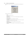
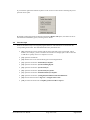
5 Starting the program
After starting the program, you will see two menus at the top of the window:
File
?
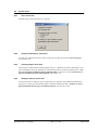
After clicking the "File" menu, either an existing system can be loaded by means of the "Load"
menu item, or a new system can be entered using "New". After clicking "File/New" you will first
see a dialogue box for selecting rectangular or triangular foundations for the following analysis.
Then, the menu bar will show ten menus:
File
Soils
Mesh
Foundations or Triangular foundations
System
Evaluation
Special
Graphics preferences
Page size + margins
?
After clicking one of these menus, the so-called menu items roll down, allowing you access to all
program functions.
The program works on the principle of What you see is what you get. This means that the screen
presentation represents, overall, what you will see on your printer. In the last consequence, this
would mean that the screen presentation would have to be refreshed after every alteration you
make. For reasons of efficiency and as this can take several seconds for complex screen contents,
the GGU-SETTLE screen is not refreshed after every alteration.
If you would like to refresh the screen contents, press either [F2] or [Esc]. The [Esc] key additionally sets the screen presentation back to your current zoom, which has the default value 1.0, corresponding to an A3 format sheet.
GGU-SETTLE User Manual
Page 10 of 108
August 2014
6 Short introduction using worked examples
6.1
Program concept
In order to calculate foundation settlements, input of the constrained modulus profile is necessary,
as well as the foundation data (width, length, foundation stress). Many comparable programs define this constrained modulus per foundation. The GGU-SETTLE program takes a different,
much more flexible path. The constrained modulus profiles are defined in a triangle mesh. At the
nodes of this triangle mesh you can edit the thickness of the layers involved. After having defined
the triangle mesh you can place the foundations within this mesh. During the following calculations the program determines the valid constrained modulus profile from linear interpolation
within the triangle concerned. Even after calculations are complete, or after placing the foundations, the triangle mesh can be edited or supplemented.
In order to secure a sensible interpolation within the constrained modulus profile mesh, it is necessary for all nodes to have the same number of layers, and for all layers to have the same constrained modulus within the mesh. The thickness of the layers, however, can be varied. If your
system has areas in which certain soil layers are not present (e.g. peat lenses only in certain areas),
then simply assign these layers a thickness of '0' at the appropriate nodes.
As, from personal experience, the reading of user manuals is a chore, there will now follow a short
description of the main program functions using the following worked examples. After studying
these sections you will be in a position to carry out calculations with the GGU-SETTLE program.
You can take the details of the program from the following chapters.
6.2
6.2.1
Analysis of rectangular foundations
System data
For example, you know the constrained modulus profile of 5 boreholes (BP 1 to BP 5) from field
investigations. The boreholes have the following coordinates:
Borehole
x [m]
y [m]
BP 1
0.0
21.0
BP 2
1.0
6.0
BP 3
12.5
15.0
BP 4
25.0
22.0
BP 5
24.0
4.0
Table 1 Borehole coordinates
GGU-SETTLE User Manual
Page 11 of 108
August 2014
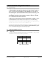
We have a 3-layer system. The individual layers have the following soil properties:
Layer
no.
Soil type
Unit weight
of soil
[kN/m³]
Constrained mod.
initial loading
[MN/m²]
Constrained mod.
reloading
[MN/m²]
Poisson'sratio
[-]
1
Silt
18
12
30
0.0
2
Sand
10
45
110
0.0
3
Clay, silty
11
6
15
0.0
Table 2 Soil types and soil properties
Unit weight input is only decisive if the limiting depth is to be calculated with a percentage value
of the overburden stress. Constrained modulus input for reloading is only decisive when foundations with excavation unloading are being processed.
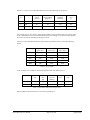
The layers at the individual boreholes, measured from ground level (GL), reach the following
depths:
Borehole
Layer base 1
[m b. GL]
Layer base 2
[m b. GL]
Layer base 3
[m b. GL]
BP 1
2.00
3.50
15.00
BP 2
2.00
4.00
15.00
BP 3
2.00
5.00
15.00
BP 4
2.00
5.00
15.00
BP 5
2.00
4.00
15.00
Table 3 Layer depths
In the example, two foundations with the designations 'F1' and 'F2' are present.
Foundation
x (left
[m]
y (bottom)
[m]
Foundation
pressure
[kN/m²]
Length
[m]
Width
[m]
F1
4.0
14.0
200.0
7.0
4.0
F2
14.0
8.0
200.0
3.0
3.0
Table 4 Foundation dimensions and pressure
Both foundations have their base at 0.8 m below ground level.
GGU-SETTLE User Manual
Page 12 of 108
August 2014
6.2.2
Define soils
First select the menu item "File/New" and activate the "Rectangular foundations" check box.
The first step in a calculation using the GGU-SETTLE program is the definition of a triangle
mesh. The nodes of the triangle mesh are described by the borehole points. The borehole points
are then connected to a triangle mesh, from which the program can interpolate the constrained
modulus profile at any point. To define the borehole points proceed as follows:
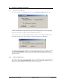
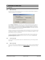
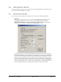
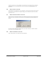
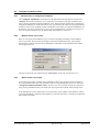
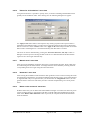
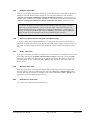
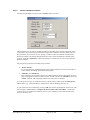
First, go to the menu item "Soils/Layers" and click the "Edit no. of soils" button. Enter '3' for the
new number of layers. Three rows are then displayed for the layers in the following dialogue box.
Enter the soil properties from Table 2 (soil types and soil properties) as shown.
GGU-SETTLE User Manual
Page 13 of 108
August 2014
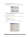
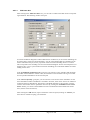
6.2.3
Define default layer depths
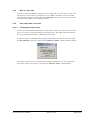
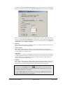
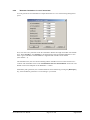
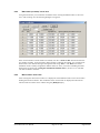
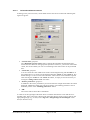
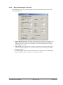
You should then select the menu item "Soils/Default layer depths" (not absolutely necessary).
As you have defined three layers using the menu item "Soils/Layers", three layers will be shown
in the dialogue box. The corresponding soil properties are also shown for information purposes.
The given depths can be edited to suit your wishes. Depths are entered as m below ground level.
For reasons of clarity, the program assumes ground level to be the same for all nodes. During the
following definition of triangular nodes, the layer depths are assigned to the appropriate nodes.
After this, the layer depths for each node can be edited as wished. If the constrained modulus
profile is equal for almost all nodes, you can save input work via the initial definition of default
layer depths. The layer depths for the example were therefore entered in the dialogue box based on
Table 3.
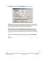
Using the "Load" button you can load a previously saved depth distribution. Using "Save" you
can save the current depth distribution to a file, in order to have them available later, without renewed input. If you select the "Apply to all" button, all current triangle nodes will be assigned
these depths. Using the "Cancel" button, you may leave the dialogue box without accepting the
alterations. You can also leave the dialogue box with "Done". Any changes will be accepted.
GGU-SETTLE User Manual
Page 14 of 108
August 2014
6.2.4
Define triangle nodes
After this initial input you can determine the position of triangle nodes (borehole points). A coordinate system is visible on the screen. If the area displayed does not correspond to the plan area of
your system, go to the menu item "Page size + margins/Manual resize (editor)" and enter the
values for your system into the dialogue box.
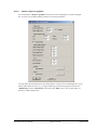
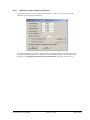
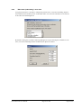
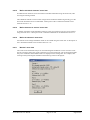
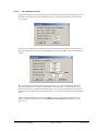
Then select the menu item "Mesh/Define nodes". Click, with the left mouse button, on the positions of the triangle nodes (= positions of points for which you know the constrained modulus
profile). In the program status bar the current coordinates of the mouse pointer are shown. Erroneous input can be undone by clicking on the node with the right mouse button. If the presentation
appears too small or too large, go to the menu item "Evaluation/Preferences" and enter a factor
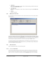
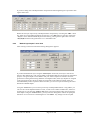
for the constrained modulus profile width and/or depth to suit your wishes. Alternatively to coordinate input using the mouse, you can enter the values in tabular form. Then select the menu item
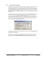
"Mesh/Edit nodes (via table)" and change the number of points to '5' using the "x nodes to edit"
button.
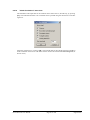
The data for the example system based on Table 1 (coordinates of drilling points) are entered in
the above dialogue box. After entering the data go to the menu item "Page size + margins/Autoresize" or alternatively [F9] in order to achieve a screen-filling visualisation of the constrained
modulus profiles.
GGU-SETTLE User Manual
Page 15 of 108
August 2014
6.2.5
Adjust layer depths of nodes
After entering nodes, you can edit the depths at the nodes for the individual layers. For this, select
the menu item "Soils/Edit layer depths". A double-click in the area of the node will then suffice
to call up the following dialogue box.
This box is absolutely identical to the box for default depths. The only difference is that any
changes made are with reference to the current node. Depths are entered as m below ground level.
Edit the input for the drilling points at which the layer depths deviate from the default section in
accordance with Table 3 (BP 1, BP 3 and BP 4).
6.2.6
Define triangle mesh
After you have defined at least 3 nodes (borehole points), you must connect these nodes to a triangle mesh to allow the program to interpolate when calculating. There are two possibilities:
"Mesh/Manual mesh" menu item
You must click on the three nodes to be connected to a triangle. Mistakenly created triangles can be deleted by clicking on the three nodes once again.
"Mesh/Automatic" menu item
The program carries out a so-called triangulation and connects all nodes to a triangle mesh.
Subsequently, you still have the possibility of deleting triangles by using the menu item
"Mesh/Manual mesh" and clicking on the three nodes of the triangle. If a triangle mesh is
already present you will be asked, before triangulation begins, if the current mesh is to be
deleted. Only in exceptional cases should you select "Supplement", as triangulation follows certain laws which may not allow sensible complementing of a current partial mesh.
For the example select the "Mesh/Automatic" menu item.
GGU-SETTLE User Manual
Page 16 of 108
August 2014
6.2.7
Define rectangular foundations
After defining the constrained modulus profile distribution throughout the triangle mesh, you can
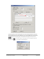
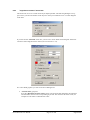
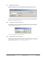
enter the foundations. For this, select the menu item "Foundations/Define".
In the dialogue box shown the first foundation ("F1" button) is already entered. Click the "New"
button. You will then see the following dialogue box:
After clicking the "Edit base data" button the data for the second foundation can be edited in
accordance with Table 4. Descriptions of the remaining buttons can be found in Section 8.4.1.
GGU-SETTLE User Manual
Page 17 of 108
August 2014
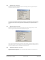
After the foundation designation you enter the depth of the foundation base (FB), the excavation
unloading, the foundation dimensions and the corner stresses. For linear stress distribution, input
of three stress values is sufficient. The fourth value then results automatically. If foundations are
already defined, you can also reach this dialogue box by double-clicking in the foundation surround on the screen.
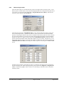
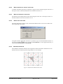
6.2.8
Check input data
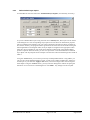
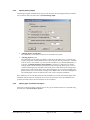
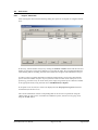
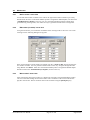
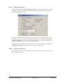
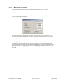
The input for the foundations can be checked using the menu item "Foundations/Check foundations". The foundations are visualised with corner stresses. In the dialogue box, specify the additional input data to be visualised:
A contour diagram of the layer base can be generated to check the layer depths that have been
entered. To do this, select the menu item "Soils/Layer base contours".
Enter the number of the required layer. Deactivate the "Coloured" check box if a normal line
diagram is required for contour visualisation. Confirm with "OK".
GGU-SETTLE User Manual
Page 18 of 108
August 2014
In the upper part of the dialogue box you can influence the number of contour lines with the input
after "Separation". If desired, change to a different smoothing out procedure. After exiting the
box using "OK" the lines of equal layer base elevation are visualised on the screen.
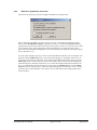
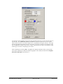
6.2.9
Specify limiting depth
Calculating rectangular foundations the program can determine the limiting depth using three
different procedures. Select the menu item "System/Limiting depth".
"Limiting depth = profile base"
The settlements are calculated to the base of the defined soil profile.
GGU-SETTLE User Manual
Page 19 of 108
August 2014
"Limiting depth = x * b"
The settlements are calculated to a depth of x * foundation width, but not deeper than the
profile base.
"Limiting depth at p %"
The settlements are calculated to a depth at which the overburden stress * p from the soil
weight corresponds to the foundation stress, but not deeper than the profile base. If foundations are close to one another (e.g. with circular foundations), you should, additionally, activate the "% limiting depth for all foundations" check box, as otherwise too shallow
limiting depths will be calculated. When determining the limiting depth with p %, any excavation unloading for the foundation concerned can be subtracted from the average foundation stress, which usually makes sense. More information on excavation unloading and
global preload stress can be had by clicking on the "Info" button in the above dialogue box.
The limiting depth will be calculated in the centre of the rectangular foundation.
If the settlement is to be calculated outside of the foundation concerned, the limiting depth of the
foundation which creates the settlement stress is also valid. Stresses above the foundation base
generate tensional stresses and will therefore not be considered.
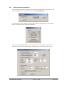
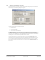
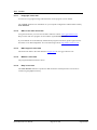
6.2.10
Specify type of settlement analysis
With the menu item "System/Analysis options" you can specify the type of settlement to be calculated. In principle, there are three different types:
"Calculate settlement at given depth"
This is usually the standard case, together with a depth of 0.0 m (= settlement at the ground
level). As the area of the foundation is indeformable, the settlement at the foundation base,
including for foundations with the base below the ground level, will be calculated. If a settlement depth > 0.0 is entered the settlement at this depth will be calculated.
GGU-SETTLE User Manual
Page 20 of 108
August 2014
"Calculate settlement at layer base"
As the layers need not necessarily be horizontally arranged, you have the possibility with
this calculation method of following the influence of settlements at certain layer boundaries. To do this, activate this check box and enter the layer number.
"Calculate settlement of a layer"
Quite often the deformation component of an individual layer is of interest. To do this, activate this check box and enter the layer number.
In the lower part of the dialogue box, you can define a so-called influence distance. The influence of a foundation on the current settlement value will only be calculated if the distance to the foundation centre is smaller than the influence distance. If you have defined a
lot of foundations the calculation time can become quite long, as, for each point at which
the settlement is calculated, the influence of all foundations is considered. The influence of
a foundation on the current settlement decreases with increasing distance. You can thus
achieve a reduction of calculation duration using the influence distance. A reliable statement on influence distances cannot be given, as the foundation loading also plays a large
role. If you are unsure, use, as in the above dialogue box, a very large value and if you are
calculating a lot of foundations allow yourself a coffee during calculations.
Any calculation and presentation can be prematurely cancelled using the right mouse
button.
"With vibrodisplacement compaction"
Activate vibrodisplacement compaction adoption after Priebe (Heinz J. Priebe, Die Bemessung von Rüttelstopfverdichtung, Ground Engineering, December 1995) using this check
box.
"Use kappa correction coefficients (DIN 4019)"
By activating this check box the kappa correction coefficients compliant with DIN 4019
Table 1 can be adopted for settlement analysis.
GGU-SETTLE User Manual
Page 21 of 108
August 2014
6.2.11
Calculate foundation settlements
After defining a foundation you can have the system calculated. In principle, we can differentiate
between analysis of foundation settlements and the analysis of user-defined settlements. The two
calculations can also be mixed. With foundation settlement we mean the settlement at special
points on the foundation:
settlement in the foundation centre
settlement at the four characteristic points
settlement at the four foundation corners.
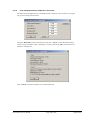
If you are only interested in settlement at the above described foundations points, select the "System/Analyse" menu item.
Activate the check box(es) of choice and click "OK". You may see a note on the specified special
preferences first. Acknowledge the notes and start the analysis. Information on analysis progress is
displayed in the status bar. Once analysis is complete the foundation settlements are entered in the
foundation centre, in the corners and in the characteristic points, depending on the preferences
specified above.
If you have calculated a system and then edited any input values (e.g. foundation dimensions,
foundation stress, type of limiting depth calculation, etc.), the program deletes all calculated settlements, as they are then no longer valid for the altered system. If you have already defined userdefined settlement points within the framework of previous calculations, you can have these settlements recalculated by activating the "Settlement at user-defined points" check box.
GGU-SETTLE User Manual
Page 22 of 108
August 2014
6.2.12
Calculate user-defined settlements
With user-defined settlements we mean analysis of settlements at any point inside or outside of the
foundations. The position of these points is not restricted to the foundation geometry. They can be
user-specified in a variety of ways.
If you are completely uninterested in the settlements at the special foundation points, you can go
directly to the "Evaluation" and "Special" menus to calculate and display user-defined settlements.
"Evaluation/Settlements at points" menu item
With the mouse, you can click on any point within the system. The calculated settlements
will then be graphically displayed.
Evaluation/Settlements on a line" menu item
With the mouse, you click on two points (start and end points of a line). The settlement
along this line will then be calculated at constant intervals. If, after calculations are complete, you switch to the "Evaluation/Automatic multi-node section" menu item (see
Section 8.7.13), you can display the settlement depression for the system section.
"Evaluation/Settlements in quadrilateral array" menu item
You click on the four points of a quadrilateral. The program then calculates the settlement
in a regular array within this quadrilateral. This function is especially useful in connection
with the "Evaluation/Settlement contours" menu item (see Section 8.7.3), as you have,
with settlements calculated in a quadrilateral, a favourable data basis for triangulation and
thus for the presentation of contours.
6.2.13
Evaluate and visualise results
After calculations are complete the results can be evaluated in a variety of ways.
"Evaluation/Settlement location display options" menu item
The calculated settlements will be displayed in their appropriate positions. If, after calculating, you have altered input values, the settlements will not be shown. You must then have
the system recalculated.
"Evaluation/Settlement contours" menu item
The program will carry out a triangulation of all calculated settlements. By interpolation
within this triangle mesh, which is not identical to the above described triangle mesh for
the constrained modulus profile, lines of equal settlement will then be drawn.
In the "Special" menu it is possible to calculate settlement depressions, stress distribution and
lines of equal settlement along straight, vertical sections.
In accordance with the principle of What you see is what you get you can, at any stage of evaluation, send the current screen contents to the printer (see menu item "File/Print and export" button
"Printer", Section 8.1.7).
GGU-SETTLE User Manual
Page 23 of 108
August 2014
6.3
6.3.1
Analysis of triangular foundations
Define borehole points
First select the menu item "File/New" and activate the "Triangular foundations" check box.
To define the drilling points proceed analogous to the descriptions in Sections 6.2.2 to 6.2.5 and
enter the coordinates, layer depths and soil properties at the drilling points in the corresponding
menu items (see Table 1 to Table 3 in the system data in Section 6.2.1).
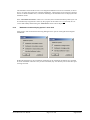
If you have previously worked through the example for analysis of rectangular foundations, the
following prompt box opens when changing to triangular foundations via "File/New":
All of the previous data on the drilling points and the triangular mesh can be retained by activating
the "Keep soil stratification" check box. The rectangular foundations can also be directly converted to triangular foundations. If the check box is deactivated the foundations must be entered
again from scratch.
6.3.2
Define triangle mesh
The triangle mesh for the constrained modulus profiles is generated analogous to the description in
Section 6.2.6. If the "Keep soil stratification" check box was activated when changing from rectangular to triangular foundations, the triangle mesh is also transferred.
GGU-SETTLE User Manual
Page 24 of 108
August 2014
6.3.3
Define triangular foundations
After defining the constrained modulus profile distribution throughout the triangle mesh, you can
enter the triangular foundations. The definition of triangular foundations is different to that of
rectangular foundations, as a much more flexible input is possible. Input of triangular foundations
is very similar to the definition of constrained modulus profiles. If the check box "Convert rectangular foundations to triangular foundations" was activated when changing from rectangular
foundations to triangular foundations, the foundations' corner points and triangle mesh are transferred directly
If you have started again from scratch, define the corner points of the triangular foundations according to Table 4 in the system data (see Section 6.2.1). You can do this with the mouse, e.g. For
this, select the menu item "Triangular foundations/Define nodes". Now click on the corner
points of the triangular foundation with the mouse. If the same system is to be calculated as in
Section 6.2, these are then the four corner points of both foundations. If you define a new triangular foundation corner point with the mouse, this node will be assigned the values given in the
menu item "Triangular foundations/Default values".
These default values can then be individually adjusted using the menu item "Triangular foundations/Edit nodes (individually)".
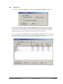
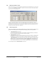
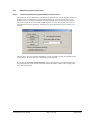
Alternatively to clicking with the mouse, you can enter the values in tabular form. To do this,
select the menu item "Triangular foundations/Edit nodes (via table)". The pre-existing data
from the conversion from rectangular foundations can be seen in the following dialogue box:
GGU-SETTLE User Manual
Page 25 of 108
August 2014
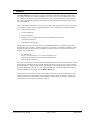
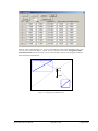
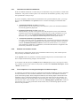
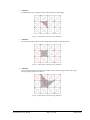
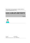
Enter the values of the dialogue box. You have thus defined 8 nodes of the foundation mesh. Now
you must only connect the nodes to a mesh. For this, select the menu item "Triangular foundations/Manual mesh" and click on three points of the foundation mesh. The triangular foundation
mesh should then look like this:
3
2.00
5.00
15.00
Figure 1 Triangular foundation mesh
GGU-SETTLE User Manual
Page 26 of 108
August 2014
6.3.4
Specify limiting depth
Calculating triangular foundations the program can determine the limiting depth using two different procedures. Select the menu item "System/Limiting depth".
"Limiting depth = profile base"
The settlements are calculated to the base of the defined soil profile.
"Limiting depth at p %"
The settlements are calculated to a depth at which the overburden stress * p from the soil
weight corresponds to the foundation stress, but not deeper than the profile base. If foundations are close to one another (e.g. with circular foundations), you should, additionally, activate the "% limiting depth for all foundations" check box, as otherwise too shallow
limiting depths will be calculated. When determining the limiting depth with p %, any excavation unloading for the foundation concerned can be subtracted from the average foundation stress, which usually makes sense. More information on excavation unloading and
global preload stress can be had by clicking on the "Info" button in the above dialogue box.
The limiting depth will be calculated in the centre of the rectangular foundation.
If the settlement is to be calculated outside of the foundation concerned, the limiting depth of the
foundation which creates the settlement stress is also valid. Stresses above the foundation base
generate tensional stresses and will therefore not be considered.
6.3.5
Specify type of settlement analysis
Analogous to the descriptions in Section 6.2.10, the type of settlement analysis is specified using
the menu item "System/Analysis options".
GGU-SETTLE User Manual
Page 27 of 108
August 2014
6.3.6
Calculate foundation settlements
After defining a foundation you can have the system calculated. In principle, we can differentiate
between analysis of foundation settlements and the analysis of user-defined settlements. The two
calculations can also be mixed. With foundation settlement we mean the settlement at special
points on the foundation:
settlement in the foundation centre
settlement at the four characteristic points
settlement at the four foundation corners.
If you are only interested in settlement at the above described foundations points, select the "System/Analyse" menu item.
For analysis of triangular foundations numerical integration is required. The integration precision
can be specified in the upper area of the dialogue box. The default value is sufficiently small for
most problems. If the calculated values appear unusual to you, or if you are somewhat cautious by
nature, enter a smaller value. This will, of course, cost you calculation time.
Activate the check box(es) of choice and click "OK". You may see a note on the specified special
preferences first. Acknowledge the notes and start the analysis. Information on analysis progress is
displayed in the status bar. Once analysis is complete the foundation settlements are entered in the
foundation centre, in the corners and in the characteristic points, depending on the preferences
specified above.
If you have calculated a system and then edited any input values (e.g. foundation dimensions,
foundation stress, type of limiting depth calculation, etc.), the program deletes all calculated settlements, as they are then no longer valid for the altered system. If you have already defined userdefined settlement points within the framework of previous calculations, you can have these settlements recalculated by activating the "Calculate settlements at user-defined points" check
box.
GGU-SETTLE User Manual
Page 28 of 108
August 2014
6.3.7
Calculate user-defined settlements
With user-defined settlements we mean analysis of settlements at any point inside or outside of the
foundations. The position of these points is not restricted to the foundation geometry. They can be
user-specified in a variety of ways.
If you are completely uninterested in the settlements at the special foundation points, you can go
directly to the "Evaluation" and "Special" menus to calculate and display user-defined settlements.
"Evaluation/Settlement at points" menu item
With the mouse, you can click on any point within the system. The calculated settlements
will then be graphically displayed.
Evaluation/Settlements on a line" menu item
With the mouse, you click on two points (start and end points of a line). The settlement
along this line will then be calculated at constant intervals. If, after calculations are complete, you switch to the "Evaluation/Automatic multi-node section" menu item (see
Section 8.7.13), you can display the settlement depression for the system section.
"Evaluation/Settlements in quadrilateral array" menu item
You click on the four points of a quadrilateral. The program then calculates the settlements
in a regular array within this quadrilateral. This function is especially useful in connection
with the "Evaluation/Settlement contours" menu item (see Section 8.7.3), as you have,
with settlements calculated in a quadrilateral, a favourable data basis for triangulation and
thus for the presentation of contours.
6.3.8
Evaluate and visualise results
Once analysis is complete the results can be evaluated in numerous ways. One of these options
was previously introduced in Section 6.2.13.
In the "Special" menu it is possible to calculate settlement depressions, stress distribution and
lines of equal settlement along straight, vertical sections.
In accordance with the principle of What you see is what you get you can, at any stage of evaluation, send the current screen contents to the printer (see menu item "File/Print and export" button
"Printer", Section 8.1.7).
6.3.9
Final comparison of rectangular/triangular foundation analysis
A comparison of calculation results for rectangular and triangular foundations will show that there
are minor differences in the calculated settlements. This is because of the different calculation
point of the limiting depth. With rectangular foundations, the limiting depth is determined in the
foundation centre. Triangular foundations do not "know" the centre point of the rectangles. For
triangular foundations, the limiting depth is determined at the centre of the triangles, which deviates from the centre of the rectangles. If you select the "Limiting depth = profile base" check box
(see Section 6.2.9), you will get the same results in both cases, as the limiting depth is then the
same for both procedures.
GGU-SETTLE User Manual
Page 29 of 108
August 2014
7 Theoretical principles
7.1
General
The program calculates the stresses and strains after the theory of elastic-isotropic half space.
Especially in the days when pocket calculators and personal computers were not yet available,
comprehensive diagrams and tables were developed. A literature list of tables can be taken from
the DIN 4019. Further to this, you are referred to the article "Stress calculation" (Spannungsberechnung) in the "Geotechnical Engineering Pocket Book" (Grundbau-Taschenbuch) (1990;
Fourth Edition; also available in english). Here you will also find the complete relationships for
stresses and strains below a rectangle in elastic-isotropic half space (formulas 8 to 10 and formulas
14 and 15). These relationships are the basis for the program.
The stress relationships are only used for limiting depth calculations and for the presentation of
stress distributions. The strains are calculated directly from the relationships given in the Geotechnical Engineering Pocket Book. A numerical integration with associated loss of precision is therefore not required.
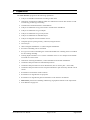
7.2
Characteristic point
The stiffness of foundations cannot be considered using the above mentioned relationships. The
foundation loading will be assumed to be a flexible load bundle, whatever the case. It is usual to
calculate the settlements at what is called the characteristic point. At this point of the foundation,
for a uniform load, the settlements for a flexible load bundle correspond to the settlement of a
rigid foundation. The position of the characteristic point is defined as follows:
Figure 2 Characteristic point
GGU-SETTLE User Manual
Page 30 of 108
August 2014
7.3
Limiting depth
Of great importance for the size of settlements is the limiting depth. The program allows definition
of limiting depth in three different ways:
"Limiting depth = profile base"
The settlements are calculated to the base of the defined soil profile.
"Limiting depth = x * b"
The settlements are calculated to a depth of x * foundation width, but not deeper than the
profile base.
"Limiting depth at p %"
The settlements are calculated to a depth at which the overburden stress * p from the soil
weight corresponds to the foundation stress.
The last possibility is also described in DIN 4019 (see at http://www.din.de). Here, a percentage
value p of 20 % is given. This is the program default value. If you have selected this type of limiting depth calculation, the program calculates the overburden stress due to the soil weight for each
foundation and compares this value to the average stress due to the foundation load at the characteristic point. The depth distribution of the unit weights for analysis of the overburden stress is
determined in the foundation centre. Any excavation unloading for the foundation can be subtracted from the foundation stress, which the usual case.
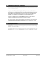
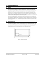
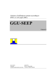
For settlement analyses, only the stress from the foundation base to the limiting depth will be
considered. Thus, for all points outside of the foundation, the limiting depth of the appropriate
foundation is valid. Figure 3 shows, in a vertical section, how the settlements of a point, A, are
composed if two foundations are defined.
Figure 3 Influence of limiting depth on settlements
GGU-SETTLE User Manual
Page 31 of 108
August 2014
If you divide a foundation into several smaller sub-foundations you should, according to
theory, get the same settlement values. However, a problem then occurs when calculating
limiting depths. The limiting depths of the sub-foundations is smaller due to the smaller
widths. Because of the differing limiting depths you will also get different settlement values. To solve this contradiction the GGU-SETTLE program offers the possibility of calculating the limiting depth from the stress distribution of all foundations (see Section 6.2.9).
If you select this possibility the stress distribution at the characteristic point is calculated
from the stresses of all foundations. In this case you will get larger settlements and, depending on the system, more appropriate results.
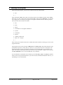
7.4
Excavation unloading and constrained modulus for reloading
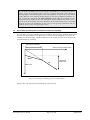
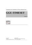
You can define excavation unloading for each foundation. The excavation unloading has the same
dimensions as the foundation stress [kN/m²]. It is constant for each foundation. If you have defined an excavation unloading, settlement analyses will be carried out to this value using the constrained modulus for reloading.
Excavation unloading
Stress at the foundation base
Es(w)
Es
Calculated
settlement
Settlement
Figure 4 Excavation unloading and constrained modulus
Figure 4 shows the settlements computed for this particular case.
GGU-SETTLE User Manual
Page 32 of 108
August 2014
8 Description of menu items
8.1
8.1.1
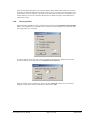
File menu
"New" menu item
You can enter a new system using this menu item. You will first be asked whether rectangular or
triangular foundations are to be generated.
The "Triangular foundations" option allows you to calculate settlements and stresses below a
flexible foundation of any shape and linear loading. By combining the triangular foundations in
mosaic-like manner, any type of load (with reference to ground plan and load size) can be easily
modelled. After selecting this menu item the "Triangular foundations" menu appears instead of
the usual "Foundations" menu (see Section 8.5).
Existing soil stratification (constrained modulus profiles) and foundations can be transferred when
changing from rectangular to triangular foundations, but when changing from triangular to rectangular foundations only the soil stratification.
Activate vibrodisplacement compaction adoption after Priebe (Heinz J. Priebe, Die Bemessung
von Rüttelstopfverdichtung, Ground Engineering, December 1995) using the "With vibrodisplacement compaction" check box.
8.1.2
"Load" menu item
You can load a file with system data, which was created and saved at a previous sitting, and then
edit the data.
8.1.3
"Save" menu item
You can save data entered or edited during program use to a file, in order to have them available at
a later date, or to archive them. The data is saved without prompting with the name of the current
file.
GGU-SETTLE User Manual
Page 33 of 108
August 2014
8.1.4
"Save as" menu item
You can save data entered during program use to an existing file or to a new file, i.e. using a new
file name. For reasons of clarity, it makes sense to use ".fda" as file suffix, as this is the suffix
used in the file requester box for the menu item "File/Load". If you choose not to enter an extension when saving, ".fda" will be used automatically.
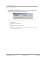
8.1.5
"Print output table" menu item
8.1.5.1
Selecting the output format
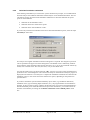
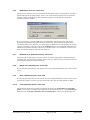
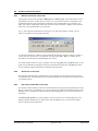
You can have a table printed containing the current analysis results. The results can be sent to the
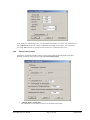
printer or to a file (e.g. for further editing in a word processor). The output contains all information on the current state of analysis, including the system data.
You have the option of designing and printing the output table as an annex to your report within
the GGU-SETTLE program. To do this, select "Output as graphics" from the following options.
If you prefer to easily print or process the data in a different application, you can send them directly to the printer or save them to a file using the "Output as ASCII" command button.
GGU-SETTLE User Manual
Page 34 of 108
August 2014
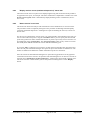
8.1.5.2
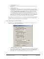
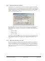
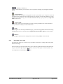
Button "Output as graphics"
If you selected the "Output as graphics" button in the previous dialogue box a further dialogue
box, in which you can define further preferences for result presentation.
You can define the desired layout for the output tables in various areas of the dialogue box. If you
need to add a header or footer (e.g. for page numbering), activate the appropriate check boxes
"With headers" and/or "With footers" and click on the "Edit" button. You can then edit as required in a further dialogue box.
GGU-SETTLE User Manual
Page 35 of 108
August 2014
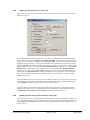
Automatic pagination can also be employed here if you work with the placeholders as described.
After exiting the dialogue boxes using "OK" you will see a further dialogue box in which you can
select the parameters to be used in the output table. If you click the "Start" button the output table
is presented on the screen page by page. To navigate between the pages, use the arrow tools
in the toolbar. If you need to jump to a given page or back to the graphical representation, click on the
GGU-SETTLE User Manual
tool. You will then see the following box:
Page 36 of 108
August 2014
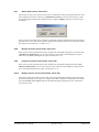
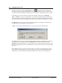
8.1.5.3
Button "Output as ASCII"
You can have your analysis data sent to the printer, without further work on the layout, or save it
to a file for further processing using a different program, e.g. a word processing application. After
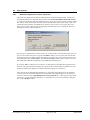
selecting the button "Output as ASCII" you will see a further dialogue box in which you can
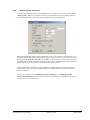
select the parameters to be used. If you click the "Start" button, the following dialogue box appears in which you can define output preferences.
In the dialogue box you can define output preferences:
"Printer preferences" group box
Using the "Edit" button the current printer preferences can be changed or a different printer
selected. Using the "Save" button, all preferences from this dialogue box can be saved to a
file in order to have them available for a later session. If you select "GGU-SETTLE.drk"
as file name and save the file in the program folder (default), the file will be automatically
loaded the next time you start the program.
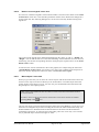
Using the "Page format" button you can define, amongst other things, the size of the left
margin and the number of rows per page. The "Header/footer" button allows you to enter
a header and footer text for each page. If the "#" symbol appears within the text, the current
page number will be entered during printing (e.g. "Page #"). The text size is given in "Pts".
You can also change between "Portrait" and "Landscape" formats.
"Print pages" group box
If you do not wish pagination to begin with "1" you can add an offset number to the check
box. This offset will be added to the current page number. The output range is defined using "From page no." "to page no.".
"Output to:" group box
Start output by clicking on "Printer" or "File". The file name can then be selected from or
entered into the box. If you select the "Window" button the results are sent to a separate
window. Further text editing options are available in this window, as well as loading, saving and printing.
GGU-SETTLE User Manual
Page 37 of 108
August 2014
8.1.6
"Printer preferences" menu item
You can edit printer preferences (e.g. swap between portrait and landscape) or change the printer
in accordance with WINDOWS conventions.
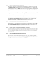
8.1.7
"Print and export" menu item
You can select your output format in a dialogue box. You have the following possibilities:
"Printer"
allows graphic output of the current screen contents (graphical representation) to the
WINDOWS standard printer or to any other printer selected using the menu item
"File/Printer preferences". But you may also select a different printer in the following
dialogue box by pressing the "Printer prefs./change printer" button.
In the upper group box, the maximum dimensions which the printer can accept are given.
Below this, the dimensions of the image to be printed are given. If the image is larger than
the output format of the printer, the image will be printed to several pages (in the above example, 4). In order to facilitate better re-connection of the images, the possibility of entering an overlap for each page, in x and y direction, is given. Alternatively, you also have the
possibility of selecting a smaller zoom factor, ensuring output to one page ("Fit to page"
button). Following this, you can enlarge to the original format on a copying machine, to ensure true scaling. Furthermore, you may enter the number of copies to be printed.
GGU-SETTLE User Manual
Page 38 of 108
August 2014
If you have activated the tabular representation on the screen, you will see a different dialogue box for output by means of the "File/Print and export" menu item button "Printer".
Here, you can select the table pages to be printed. In order to achieve output with a zoom
factor of 1 (button "Fit in automatically" is deactivated), you must adjust the page format
to suit the size format of the output device. To do this, use the dialogue box in "File/Print
output table" button "Output as graphics".
"DXF file"
allows output of the graphics to a DXF file. DXF is a common file format for transferring
graphics between a variety of applications.
"GGUCAD file"
allows output of the graphics to a file, in order to enable further processing with the
GGUCAD program. Compared to output as a DXF file this has the advantage that no loss
of colour quality occurs during export.
"Clipboard"
The graphics are copied to the WINDOWS clipboard. From there, they can be imported into other WINDOWS programs for further processing, e.g. into a word processor. In order
to import into any other WINDOWS program you must generally use the "Edit/Paste"
function of the respective application.
"Metafile"
allows output of the graphics to a file in order to be further processed with third party software. Output is in the standardised EMF format (Enhanced Metafile format). Use of the
Metafile format guarantees the best possible quality when transferring graphics.
If you select the "Copy/print area" tool
from the toolbar, you can copy parts of
the graphics to the clipboard or save them to an EMF file. Alternatively you can send
the marked area directly to your printer.
Using the "Mini-CAD" program module you can also import EMF files generated using other GGU applications into your graphics.
GGU-SETTLE User Manual
Page 39 of 108
August 2014
"MiniCAD"
allows export of the graphics to a file in order to enable importing to different GGU applications with the Mini-CAD module.
"GGUMiniCAD"
allows export of the graphics to a file in order to enable processing in the GGUMiniCAD
program.
"Cancel"
Printing is cancelled.
8.1.8
"Batch print" menu item
If you would like to print several annexes at once, select this menu item. You will see the following dialogue box:
Create a list of files for printing using "Add" and selecting the desired files. The number of files is
displayed in the dialogue box header. Using "Delete" you can mark and delete selected individual
files from the list. After selecting the "Delete all" button, you can compile a new list. Selection of
the desired printer and printer preferences is achieved by pressing the "Printer" button.
You then start printing by using the "Print" button. In the dialogue box which then appears you
can select further preferences for printer output such as, e.g., the number of copies. These preferences will be applied to all files in the list.
8.1.9
"Exit" menu item
After a confirmation prompt, you can quit the program.
8.1.10
"1, 2, 3, 4" menu items
The "1, 2, 3, 4" menu items show the last four files worked on. By selecting one of these menu
items the listed file will be loaded. If you have saved files in any other folder than the program
folder, you can save yourself the occasionally onerous rummaging through various sub-folders.
GGU-SETTLE User Manual
Page 40 of 108
August 2014
8.2
8.2.1
Soils menu
"Layers" menu item
After clicking this menu item the following dialog box opens for rectangular or triangular foundations:
If necessary, edit the number of layers by clicking the "Edit no. of soils" button and enter the new
number of soil layers. In the above dialogue you can enter the name, the constrained modulus for
initial loading and for reloading, Poisson's ratio and the unit weights of the individual soil layers
In order to ensure a sensible interpolation within the triangle mesh it is necessary that all nodes
possess the same number of layers. If your system has areas in which certain soil layers are not
present (e.g. peat lenses only in certain areas), then simply assign these layers a thickness of '0.0'
at the appropriate nodes, using the menu item "Soils/Default layer depths".
If nu equals 0.0 for all soils, the value of nu displayed in the Soil properties legend can then be
switched off (see Section 8.9.9)
The current stratification with all corresponding data can be saved to a separate file using the
"Save" button in order to have it available for a different system, without a lot of typing work,
using the "Load" button.
GGU-SETTLE User Manual
Page 41 of 108
August 2014
If you are working with vibrodisplacement compaction the following dialog box opens after clicking this menu item:
Define the soil layer improved by vibrodisplacement compaction by activating the "VDC" check
box. Enter the corresponding parameters for this layer (see "Info" button). The ratio of the areas
"A(C)/A" can be determined and adopted in the table by pressing the far right button. The ratio
"E(C)/E(B)" should not be greater than 15 to a maximum of 20.
8.2.2
"Default layer depths" menu item
After clicking on this menu item the following dialogue box appears:
If you have defined three layers using the "Soils/Layers" menu item, three layers will also be
shown in this dialogue box. The corresponding constrained moduli are also shown for information
purposes. The given depths can be edited to suit your wishes. Depths are entered as m below
ground level. During the following definition of triangular nodes, these layer depths are assigned
to the appropriate nodes. The layer depths for each node can be edited as wished. If the constrained modulus profile is equal for almost all nodes, you can save input work during the initial
definition of default depths.
Using the "Load" button you can load a previously saved depth distribution. Using "Save" you
can save the current depth distribution to a file, in order to have them available later, without renewed input. If you select the "Apply to all" button, all current triangle nodes will be assigned
these depths. Using the "Cancel" button, you may leave the dialogue box without accepting the
alterations. You can also leave the dialogue box with "Done". Any changes will be accepted.
GGU-SETTLE User Manual
Page 42 of 108
August 2014
8.2.3
"Layer base contours" menu item
This menu item serves as a check for the layer depth input data. The following dialogue box appears where you enter the number of the layer for which you would like to see a contour diagram
of the base.
If you activate the "Coloured" check box you will see a colour filled contour diagram. Otherwise
a normal contour diagram will be drawn (also see Section 8.7.3.2).
For colour-filled graphics you will see the above dialogue box.
"Contour data" group box
Press the "Determine extreme values" button. The program then determines the minimum
and maximum values for the corresponding layer base. You can then edit these values, for
example in order achieve a defined start value.
GGU-SETTLE User Manual
Page 43 of 108
August 2014
"Colour fill" group box
You can control the colour subdivisions of the contour diagram using "No. of colours". In
the example above, 16 colours will be displayed between "Colour 1" and "Colour 2". The
default setting is a colour course from red to blue. These colours can be edited as required
after selecting the "Colour 1" and "Colour 2" buttons, or simply reverse the choice by selecting the "Change colour series" check box.
"Further preferences" group box
In addition to the colour presentation you can also have the triangle mesh and/or the outline
displayed. Additional contour lines can also be drawn. Line labelling preferences can be
defined by means of the "Labelling preferences" button.
"OK"
The colours will be drawn after confirmation. A colour bar at the right edge of the sheet allows correlation between the colour and the corresponding value. If this colour bar is
drawn in the right page margin, specify a larger value for the right plotting margin (e.g. 25
mm) in the "Page size + margins/Page size and margins" menu item (see Section 8.10.5).
8.2.4
"Edit layer depths" menu item
This menu item allows editing of the base of a layer at the individual nodes of the triangle mesh.
After clicking the menu item or activation using [F3] a message box opens. After double-clicking
near the node to be edited you can change the depth of the layer base.
8.2.5
"Determine layer depths" menu item
Have the constrained modulus profile displayed for any point within the triangle mesh. Click the
required point after selecting this menu item or activation via [F7]. The results for the selected
point are then displayed in a dialogue box.
GGU-SETTLE User Manual
Page 44 of 108
August 2014
8.2.6
"Duplicate layer" menu item
Sometimes it is necessary to duplicate a layer into an existing system. Using the previously described menu items this is strenuous.
A new layer can be defined by partitioning an existing layer. The depth range of the selected layer
is divided into 2 new layers with the same depth. The final depth of the constrained modulus
profile thus remains neutral. The soil properties of the selected layer are adopted for both new sublayers.
8.2.7
"Raise layer base" menu item
Sometimes it is necessary to raise or lower the base of layer in an existing system by a certain
amount. Using this menu items the following dialogue box appears:
A layer can be selected and raised or lowered by a given amount. Lowering of a layer is achieved
using negative values. This action applies to all constrained modulus profiles. If the layer above or
below are incompatible, the rise will limited to the necessary value.
8.2.8
"Standardise layer base" menu item
With this menu item a selected layer in all constrained modulus profiles can be retroactively assigned a fixed value as layer base.
GGU-SETTLE User Manual
Page 45 of 108
August 2014
8.3
8.3.1
Mesh menu
"Define nodes" menu item
Use the left mouse button to define a new node or the right mouse button to delete a previously
defined node. Each new constrained modulus profile is assigned the default depths (see menu item
"Soils/Default layer depths", Section 8.2.2). If a constrained modulus mesh has already been
generated using existing nodes, new nodes can only be generated outside of the existing mesh.
8.3.2
"Edit nodes (via table)" menu item
Using this menu item you can edit the coordinates of the existing nodes or enter new ones. After
clicking on it the following dialogue box appears:
If the current number of nodes needs to be edited, click the "x nodes to edit" button and enter the
new number of nodes. It is also possible to delete nodes in this way. Navigate through the table
using "Forw." and "Back". Each new constrained modulus profile is assigned the default depths
defined in menu item "Soils/Default layer depths" (see Section 8.2.2).
8.3.3
"Move nodes" menu item
After clicking this menu item an info box is displayed. The nodes (constrained modulus profile)
can be moved when holding the left mouse button. The coordinates of the current node are displayed in the title bar. The last node movement can be undone using the [Backspace] key.
GGU-SETTLE User Manual
Page 46 of 108
August 2014
8.3.4
"Edit nodes (individually)" menu item
Using this menu item it is possible to retroactively edit individual nodes of the constrained
modulus mesh. By double-clicking near a node the following dialogue box opens, allowing the
coordinates to be edited.
After clicking the "Layer depths" button in the above dialogue box or by clicking directly in the
constrained modulus profile, the layer depth dialogue box opens; it can also be opened via the
menu item "Soils/Edit layer depths" (see Section 8.2.4).
8.3.5
"Generate nodes in array" menu item
The nodes can be defined on an array using this menu item: A dialogue box opens for specifying
the type of array:
"Line"- along one or more lines,
"Rectangle" - in one or more rectangles,
"Quadrilateral" - in one or more quadrilaterals.
The procedure is similar for all three cases. Therefore, only the rectangles will be described.
"Rectangle"
GGU-SETTLE User Manual
Page 47 of 108
August 2014
Enter the corner points of the array and the number of subdivisions. If one of the node points thus
generated were to lie within an existing mesh, node generation is aborted with an error message
and no further nodes are generated.
If an array is defined using a line the coordinates of the two end points are entered and those of the
four corners for a quadrilateral array.
8.3.6
"Manual mesh" menu item
After input of the nodes this menu item is used to define the mesh. Three nodes must be clicked
using the left mouse button. An triangle element can be deleted by selecting the three corresponding nodes once again using the left mouse button.
8.3.7
"Automatic" menu item
After entering the mesh nodes automatic mesh generation can be carried out using this menu item
(Delauney triangulation). If a triangle mesh already exists it can be either deleted or supplemented.
Only in exceptional cases you should select the "Supplement" button, as triangulation follows
certain laws which may not allow sensible complementing of a current partial mesh.
8.3.8
"Round off" menu item
During Delauney triangulation a triangle mesh is generated that envelops all nodes. This can lead
to acute-angled triangle elements in the boundary regions. These triangles can be removed from
the triangle mesh using this menu item.
The radius ratio describes the relationship between external radius and internal radius of a triangle.
For an equilateral triangle, this ratio equals 2.0 (optimum). Before you arrive at the dialogue box
above you will be shown the maximum and minimum radius ratios. In the example above, all
external triangles with a radius ratio greater than 6 will be removed. To avoid chaos, only exterior
triangles will be removed.
8.3.9
"Delete nodes and mesh" menu item
With this menu item you can delete selected system triangles. You must first click four points in
anti-clockwise direction. All triangles with their centroid within this quadrilateral will be deleted.
If the "Delete nodes and mesh" button is pressed, the complete mesh and all nodes are deleted.
GGU-SETTLE User Manual
Page 48 of 108
August 2014
8.3.10
"Auto node and mesh" menu item
With this it is possible to quickly generate a rectangular constrained modulus mesh with default
depths for further processing. The following dialogue box opens for entering the corner coordinates of a rectangular mesh.
If the "Include all foundations" button is clicked the program automatically searches for the most
suitable coordinates and enters them in the dialogue box.
8.3.11
"Refine individual elements" menu item
The program allows the refinement of a current triangle mesh. Refinement is generally only then
necessary when you would like to supplement a current triangle mesh with further, possibly ficticious, nodes.
Using this menu item it is possible to select individual elements of the constrained modulus mesh
for refinement, after selecting the refining method:
Three different methods can be used for triangle mesh refinement. Method '3' generally gives the
best mesh refinement and is recommended. A description of the 3 refinement methods can be
found in Section 8.3.15.
GGU-SETTLE User Manual
Page 49 of 108
August 2014
8.3.12
"Refine elements in section" menu item
A number of elements previously enveloped in a polygon can be refined using this menu item. A
description of the 3 refinement methods can be found in Section 8.3.15.
8.3.13
"Refine all elements" menu item
All elements of the triangle mesh can be refined using this menu item. A description of the 3 refinement methods can be found in Section 8.3.15.
8.3.14
"Save/Load" menu item
The nodes and triangle elements of the constrained modulus mesh can be saved or loaded. The
following dialogue box opens:
Using files with the ".ggu_stei" extension it is possible to open constrained modulus meshes created using the GGU-SLAB analysis program in GGU-SETTLE or, in the opposite direction, to
export from GGU-SETTLE to GGU-SLAB.
8.3.15
Refinement methods
Three different refinement methods can be applied for element refinement. Refinement will be
demonstrated on the following mesh using element 23 as an example.
Figure 5 Refinement demonstration mesh
GGU-SETTLE User Manual
Page 50 of 108
August 2014
"Method 1"
An additional node is generated in the centroid of the selected triangle.
Figure 6 FEM mesh refinement using Method 1
"Method 2"
The selected triangle element and the neighbouring triangle element are halved.
Figure 7 FEM mesh refinement using Method 2
"Method 3"
A new triangle element is inserted at the median of the clicked triangle element. The neighbouring triangle elements are halved.
Figure 8 FEM mesh refinement using Method 3
GGU-SETTLE User Manual
Page 51 of 108
August 2014
8.4
Foundations menu
8.4.1
"Define" menu item
8.4.1.1
Create/select foundations
If you are working with rectangular foundations, you will see the following dialogue box for inputting new or editing existing foundations using this menu item:
Three foundations are already present in the dialogue box. The entered foundation designations
are shown on the respective buttons. The following actions are possible:
"To menu bar"
You return to the original menu bar.
"New"
You can now enter data for a new foundation.
"F1", "F2"
By clicking the buttons labelled with the foundation designation you can open and edit the
data for the corresponding foundation.
GGU-SETTLE User Manual
Page 52 of 108
August 2014
8.4.1.2
Operations on selected foundation
After clicking on "New" or on the button of an existing foundation, the following dialogue box
opens:
The following operations are possible:
"Done"
You return to the original menu bar.
"Edit base data"
You can enter or edit the base data for the corresponding foundation (see the following
Section 8.4.1.3).
"Delete foundation"
After a safety request, the current foundation can be deleted.
"View results"
The calculated settlements will be displayed. If certain settlement values have not yet been
calculated, the corresponding entries will remain empty.
"Print results"
The results for the currently selected foundation will be sent to the printer.
"Duplicate foundation"
You can duplicate the current foundation. You can then edit the base data of the duplicated
foundation.
GGU-SETTLE User Manual
Page 53 of 108
August 2014
8.4.1.3
Edit base data
After clicking in the "Edit base data" box, you can enter or edit the base data for the corresponding foundation. The following window will open:
You enter foundation designation and foundation base. Furthermore, an excavation unloading can
be entered. If the value excavation unloading > 0.0, the constrained moduli for reloading will be
used in settlement analyses, for the proportion of the excavation unloading which is "re-used".
This corresponds to the reloading case of a time-settlement diagram. For the load component over
and above this, or for a system without excavation unloading, the constrained modulus for initial
loading will be used.
In the "Foundation coordinates in m" group box you enter the x and y ordinates and the length
and width of the foundation. Further to this, an inclination to the horizontal can be given so that
non-axis-parallel foundations can also be analysed.
In the "Stresses [kN/m²]" group box you can enter the corner stresses of the foundation. As the
stress distribution within a foundation is assumed to be linear, three corner stresses are sufficient
to describe the stress distribution. The fourth is calculated internally by the program. It will be
visible in the window when it opened the next time. By clicking the "Calculate stresses via M
and V" button, you can have the foundation stresses calculated from the moment and vertical
force (if these values are known).
After clicking the "OK" button, input or alterations will be accepted, clicking on "Cancel" you
leave the box without accepting your alterations.
GGU-SETTLE User Manual
Page 54 of 108
August 2014
8.4.2
"Determine graphically" menu item
This menu item allows the input of rectangular foundations using the mouse.
After confirming with "OK" you click on the two corners of a foundation with the left mouse
button. If the "Foundation at angle to x-y axes" check box is activated an inclined foundation
(inclined to the horizontal) can be entered with mouse support. In this case you must click on three
points with the mouse. After defining the points the dialogue box for entering the basic data
opens, allowing a foundation designation to be entered, among other things (see the input explanations in Section 8.4.1.3).
You can greatly simplify input if you have a scanned foundation template. You can integrate such
graphics using the Mini-CAD system. The scaling of the graphics is a problem which is easy to
overcome. If you know the separation of two points in the template then simply draw a line with
Mini-CAD, which connects these two points. Then double-click on this line. In the dialogue box
which then appears, the length of the line is given. From this length and the known length of the
line, you can determine the scale discrepancy. Then select the "Modify object" icon from MiniCAD and enter the scale distortion. Voila! The imported graphics are now true to scale. You now
need only click on the foundation corner points. You can then delete the scanned graphics from
the presentation.
GGU-SETTLE User Manual
Page 55 of 108
August 2014
8.4.3
"Values for all foundations" menu item
Using this menu item it is possible to specify certain foundation data globally for all foundations.
After clicking on it the following dialogue box appears:
The following input data can be globally specified:
foundations base;
excavation unloading;
corner stresses of the foundations.
An "Apply to all" button follows each input box. By clicking any button the respective data is
adopted for all foundations. You then return to the above dialogue box and can edit further data or
exit the box via the "Cancel" button. The "Apply to all" button adopts all data for all foundations.
The dialogue box is closed automatically after this button is clicked.
The values entered above are saved as default values by pressing the "Default values" button.
These default values are adopted as the basic data for graphically generated foundations (see Section 8.4.2) and for foundations generated by the program (see Sections 8.4.9 to 8.4.11). Subsequent changes to the data can be made at any time via the menu item "Foundations/Define" (see
Section 8.4.1).
GGU-SETTLE User Manual
Page 56 of 108
August 2014
8.4.4
"Results" menu item
The results of the settlement analysis for selected foundations can be viewed in a message box
using this menu item. If the system has not yet been analysed, only the foundation dimensions and
the limiting depth are displayed in the message box. For example, after clicking an analysed foundation the following results are displayed:
8.4.5
"Check foundations" menu item
The foundation input data can be checked via this menu item or, alternatively, by pressing [F8].
The individual elements to be visualised can be specified using the check boxes in the dialogue
box.
GGU-SETTLE User Manual
Page 57 of 108
August 2014
Adopt the preferences by pressing "OK". The selected data are then displayed in the foundations
visualised on the screen. The abbreviations used are described in the General legend (see Section 8.9.8).
8.4.6
"Stress contours" menu item
The foundation stress distributions can be visualised as a coloured contour diagram with the aid of
this menu item. The procedure is in complete analogy to the visualisation of layer base contours
(see Section 8.2.3).
8.4.7
"Delete individual foundations" menu item
With this menu item individual foundations can be deleted. The program will go through all foundations in the order in which they were entered. For each foundation the following dialogue box
appears:
If you do not want to delete the foundation shown, click "No". If there are a number of foundations, the box for next foundation opens.
8.4.8
"Delete all foundations" menu item
After a safety prompt, you can delete all current foundations.
GGU-SETTLE User Manual
Page 58 of 108
August 2014
8.4.9
"Generate foundations in a row" menu item
You can generate several foundations of equal dimensions in a row. The following dialogue box
opens:
First, enter the x and y ordinates of the first foundation. Define the length and width of all foundations. With "Spacing x" and "Spacing y" the displacement of the generated foundations to each
other is given. The name of the foundation is supplemented with the current number
(start number = 1).
The foundation base, the excavation unloading and the foundation stresses will be entered in accordance with the default values in the "Foundation/Values for all foundations" menu item. The
default values can be adapted via the "Stresses …" button.
Immediately after generation, the created foundations can be deleted by pressing the [Backspace]
key, if the foundation generation is not according to your wishes.
GGU-SETTLE User Manual
Page 59 of 108
August 2014
8.4.10
"Generate circular foundation" menu item
Using this menu item you can combine several foundations to a circular foundation.
First, enter the x and y ordinates of the centre point, and the diameter of the foundation. The circular foundation will be made up of rectangular foundations. The modelling of a circular foundations
is more precise with a large amount of foundations. However, calculation time is then longer. The
name of the foundation is supplemented with the current number (start number = 1).
The foundation base, the excavation unloading and the foundation stresses will be entered in accordance with the default values in the "Foundation/Values for all foundations" menu item. The
default values can be adapted via the "Stresses …" button. Alternatively, the stresses can be calculated via the vertical load V and the moments M(x) and M(y). Activate the "Stresses via M and
V" check box. Then enter the corresponding data for the stress analysis via the now active "M and
V" button.
Immediately after generation, the created foundations can be deleted by pressing the [Backspace]
key, if the circular foundation generated is not according to your wishes. Optimum circular foundations can be generated with triangular foundations, as adjustment to the foundation geometry is
much better using triangles (see "Triangular foundations/Generate foundations" menu item,
Section 8.5.21).
GGU-SETTLE User Manual
Page 60 of 108
August 2014
8.4.11
"Generate annular foundation" menu item
In complete analogy to circular foundations (see Section 8.4.10), you can generate an annular
foundation using rectangular foundations.
You need only additionally enter the interior diameter. Optimum annular foundations can be generated with triangular foundations, as adjustment to the foundation geometry is much better using
triangles (see "Triangular foundations/Generate foundations" menu item, Section 8.5.21).
GGU-SETTLE User Manual
Page 61 of 108
August 2014
8.5
8.5.1
Triangular foundations menu
General notes on triangular foundations
The "Triangular foundations" menu appears if the appropriate selection has been made in the
"File/New" menu item (see Section 8.1.1). With this, it is possible to calculate settlements and
stresses below a flexible triangular foundation of any shape and linear loading. By combining the
triangular foundations in mosaic-like manner, any type of load (with reference to ground plan and
load size) can be easily modelled. Further information on the subject of triangular foundations can
be found in "Setzungen und Spannungen unter Dreiecksfundamenten" ("Settlements and Stresses
below Triangular Foundations"), Dr. Johann Buß, Geotechnik 22 (1999) No. 1.
8.5.2
"Default values" menu item
Here you can specify the foundation stress, excavation unloading and depth of the foundation
base. If you prefer, the excavation unloading can be determined automatically. The program
automatically calculates the excavation unloading from the depth of the foundation base and the
unit weight of the soil.
The unit weight of the soil is defined in the "Soils/Layers" menu item (see Section 8.2.1).
8.5.3
"Define nodes" menu item
Use the left mouse button to define a new foundation node or the right mouse button to delete a
previously defined node. Each new foundation node is assigned the default stress (see menu item
"Triangular foundations/Default values", Section 8.5.2). If a mesh has already been generated
using existing foundation nodes, new nodes can only be generated outside of the existing mesh.
In the dialogue box for this menu item it is also possible to select whether node numbers, stresses,
excavation unloading or foundation base depths are entered at the nodes. A change of visualisation
always affects all nodes.
GGU-SETTLE User Manual
Page 62 of 108
August 2014
8.5.4
"Edit nodes (via table)" menu item
Using this menu item you can edit the coordinates of the existing foundation nodes or enter new
ones. After clicking on it the following dialogue box appears:
If the current number of nodes needs to be edited, click the "x nodes to edit" button and enter the
new number of nodes. It also possible to delete nodes by reducing the number. Any existing foundation mesh is also deleted. Navigate through the table using "Forw." and "Back". Each new
foundation node is initially assigned the default values for stress, excavation unloading and foundation base (see menu item "Triangular foundations/Default values", Section 8.5.2). The data
can then be edited in the table.
8.5.5
"Move nodes" menu item
After clicking this menu item an info box is displayed. The foundation nodes can be moved when
holding the left mouse button. The coordinates of the current node are displayed in the title bar.
The last node movement can be undone using the [Backspace] key.
GGU-SETTLE User Manual
Page 63 of 108
August 2014
8.5.6
"Edit nodes (individually)" menu item
Using this menu item it is possible to subsequently edit the stress, excavation unloading, depth of
the foundation base and the position of individual nodes. First select the information to be entered
at the nodes from the dialogue box.
By double-clicking near a node the following dialogue box opens, allowing the coordinates or the
stress, excavation unloading and the foundation base depth to be edited.
GGU-SETTLE User Manual
Page 64 of 108
August 2014
8.5.7
"Modify values" menu item
After activating this menu item it is possible to modify subsequently the stresses, excavation
unloading or foundation bases at all foundation nodes. The following dialogue box appears:
The current values will be modified with a constant in accordance with the selected specified calculation type. The modification is valid for all nodes. This function allows fast editing of the described values with a large number of nodes.
8.5.8
"Assign values in section" menu item
Selected foundation nodes can be subsequently assigned new values for stress, excavation unloading or foundation base. Define an anticlockwise quadrilateral enclosing the nodes to be edited.
The following dialogue box then opens:
Select the required parameter and enter the new value.
8.5.9
"Generate nodes in array" menu item
Geometric shapes allowing automatic node generation on selected subdivisions can be selected for
simplified foundation node input using this menu item. This functions analogous to the menu item
"Mesh/Generate nodes in array", which is described in Section 8.3.5.
GGU-SETTLE User Manual
Page 65 of 108
August 2014
8.5.10
"Values for all foundations" menu item
Using this menu item it is possible to specify stress, excavation unloading and foundations base
globally for all foundation nodes. After clicking on it the following dialogue box appears:
An "Apply to all" button follows each input box. By clicking any button the respective data is
adopted for all foundation nodes. You then return to the above dialogue box and can edit further
data or exit the box via the "Cancel" button. The "Apply to all" button adopts all data for all foundation nodes. The dialogue box is closed automatically after this button is clicked.
The stress can also be determined by pressing the "Stress for all from V, Mx, My:" button. A
dialogue box then opens for entering the data. If the stress is determined from this data the dialogue box also closes again automatically.
8.5.11
"Manual mesh" menu item
After input of the foundation nodes this menu item is used to define the mesh. Three nodes must
be clicked using the left mouse button. An triangle element can be deleted by selecting the three
corresponding nodes once again using the left mouse button.
8.5.12
"Automatic" menu item
After entering the foundation nodes automatic mesh generation can be carried out using this menu
item (Delauney triangulation). If a triangle foundation mesh already exists it can be either deleted
or supplemented. Only in exceptional cases you should select the "Supplement" button, as triangulation follows certain laws which may not allow sensible complementing of a current partial
mesh.
8.5.13
"Delete nodes and mesh" menu item
With this menu item you can delete selected foundation triangles. You must first click four points
in anti-clockwise direction. All triangles with their centroid within this quadrilateral will be deleted. If the "Delete nodes and mesh" button is pressed, the complete mesh and all foundation
nodes are deleted.
GGU-SETTLE User Manual
Page 66 of 108
August 2014
8.5.14
"Refine individual elements" menu item
Foundation mesh elements can be selected for individual refinement using this menu item, after
selecting the refining method.
Three different methods can be used for triangle mesh refinement. Method '3' generally gives the
best mesh refinement and is recommended. A description of the 3 refinement methods can be
found in Section 8.3.15.
8.5.15
"Refine elements in section" menu item
A number of elements of the foundation mesh previously enveloped in a polygon can be refined
using this menu item. A description of the 3 refinement methods can be found in Section 8.3.15.
8.5.16
"Refine all elements" menu item
All elements of the triangle foundation mesh can be refined using this menu item. A description of
the 3 refinement methods can be found in Section 8.3.15.
8.5.17
"Results" menu item
The results of the settlement analysis for selected triangular foundations can be viewed in a message box using this menu item. If the system has not yet been analysed, only the triangular foundation point coordinates and foundation base are displayed in the message box. For example, after
clicking an analysed triangular foundation the following results are displayed:
GGU-SETTLE User Manual
Page 67 of 108
August 2014
8.5.18
"Check foundations" menu item
The foundation node input data can be checked via this menu item or, alternatively, by pressing
[F8]. The individual elements to be visualised can be specified using the check boxes in the dialogue box.
Adopt the preferences by pressing "OK". The selected data are then displayed in the foundation
nodes visualised on the screen. The abbreviations used are described in the General legend (see
Section 8.9.8).
GGU-SETTLE User Manual
Page 68 of 108
August 2014
8.5.19
"Contours" menu item
In analogy to the menu item "Foundations/Stress contours" the stress distribution in the triangular foundations can be visualised as a coloured contour diagram with the aid of this menu item.
The following dialogue box opens:
Beside the stresses, the excavation unloading, the foundation bases or the limiting depths can be
visualised as contours. Choose between normal line, coloured or 3D visualisation. If the "With
triangular foundations" check box is activated, the foundation mesh is also visualised. The values given in the option box are entered at the foundation nodes.
Details of contour visualisation (normal, coloured, 3D) can be found in the menu item "Evaluation/Settlement contours" (see Section 8.7.3) in the respective sub-sections.
8.5.20
"Test mesh" menu item
By activating this menu item, the foundation mesh will be investigated with reference to overlapping of individual triangles.
GGU-SETTLE User Manual
Page 69 of 108
August 2014
8.5.21
"Generate foundations" menu item
It is possible to automatically generate foundations. First, select the required type of foundation in
the following dialogue box:
In contrast to the automatic generation of rectangular foundations, the variously shaped foundations are configured using triangular foundations for this menu item. In this way it is possible to
model the shape and loading of a foundation much more easily. The "Rectangular foundation"
function considers, if necessary, the case of a foundation which separates from the soil (foundation gap). If this is the case, a correspondingly smaller foundation will be drawn.
The following foundations can be generated:
"Circular foundation"
A circular foundation can be compiled from several triangular foundations. Input is made
in analogy to the menu item "Foundations/Generate circular foundation". A description
can be found in Section 8.4.10.
"Elliptical foundation"
An elliptical foundation can be compiled from several triangular foundations. Input is
analogous to the menu item "Foundations/Generate circular foundation". Different values must be entered for the diameter in x and y directions. A description can be found in
Section 8.4.10.
"Annular foundation"
An annular foundation can be compiled from several triangular foundations. Input is made
in analogy to the menu item "Foundations/Generate annular foundation". A description
can be found in Section 8.4.11.
"Foundations in a row"
Several uniformly sized footing foundations can be generated in a row: Input is made in
analogy to the menu item "Foundations/Generate foundations in a row". A description
can be found in Section 8.4.9.
"Rectangular foundation"
A rectangular foundation can be generated by defining the coordinates of the bottom left
corner in the dialogue box, as well as the length, breadth and any foundation inclination. In
addition, the vertical force and the moments in x and y direction are defined. If base tilt occurs a foundation correspondingly reduced in size will be generated.
GGU-SETTLE User Manual
Page 70 of 108
August 2014
8.6
8.6.1
System menu
"Info" menu item
The following system information e.g., appears:
8.6.2
"Project identification" menu item
You can enter a description of the current system; this will then be used in the General legend
(see Section 8.9.8).
8.6.3
"Limiting depth" menu item
The program can determine the limiting depth using 2 or 3 different procedures, depending on the
type of foundation used. The methods were described in detail in the brief introduction (see "Analysis of rectangular foundations/Specify limiting depth" in Section 6.2.9 and "Analysis of triangular foundations/Specify limiting depth" in Section 6.3.4).
8.6.4
"Analysis options" menu item
Use this menu item to define the type of settlement to be analysed. Three different fundamental
options exist, which were described in detail in the brief introduction under "Analysis of rectangular foundations/Specify type of settlement analysis" (see Section 6.2.10).
GGU-SETTLE User Manual
Page 71 of 108
August 2014
8.6.5
"Analyse" menu item
Analysis of foundation settlements is started via various dialogue boxes, depending on the type of
foundation selected. The description of analysis of rectangular foundations can be found in
"Analysis of rectangular foundations/Calculate foundation settlements" (see Section 6.2.11).
The description of analysis of triangular foundations can be found in the brief introduction under
"Analysis of triangular foundations/Calculate foundation settlements" (see Section 6.3.6).
If you have calculated a system and then edit the foundation data, the program internally
deletes all calculated settlements, as they are then no longer valid for the altered system.
You should therefore always evaluate such a system first. Alternatively, you have the possibility of saving the calculation data using the "File/Save" menu item. Any calculated settlements will be saved with the file and are then available for later evaluation.
8.6.6
"Precision" menu item (for triangular foundations only)
If you are working with triangular foundations, you can specify the precision of the numerical
integration using this menu item. A high degree of precision leads to longer calculation times and
vice versa. You must weight up between the complexity of the foundation and the desired precision.
8.6.7
"Undo" menu item
If you have carried out any changes to dialog boxes or moved objects to a different position on the
screen after selecting the "Graphics preferences/Move objects" menu item or using the [F11]
function key, this menu item will allow you to undo the movements. This function can also be
reached by using the key combination [Alt] + [Back] or the appropriate tool in the toolbar (see
Section 8.9.6).
8.6.8
"Restore" menu item
When this menu item is selected the last change made in a dialog box or the last change in the
position of objects, which you undid using the menu item "Page size + margins/Undo" will be
restored. This function can also be reached by using the key combination [Ctrl] + [Back] or the
appropriate tool in the toolbar (see Section 8.9.6).
8.6.9
"Preferences" menu item
You can activate or deactivate the undo functions.
GGU-SETTLE User Manual
Page 72 of 108
August 2014
8.7
8.7.1
Evaluation menu
"Preferences" menu item
Graphics visualisation preferences can be specified via this menu item. The following box opens
for rectangular foundations:
Objects added using Mini-CAD are normally drawn via the system representation. If the MiniCAD objects are to be positioned behind the graphics this can be specified in the pop-up menu of
the Mini-CAD module (layer dialogue in Mini-CAD/"Presentation" button).
By deactivating the corresponding check boxes in the menu item "Page size + margins/Page size
and margins" the defined borders and page margins may be switched off (see Section 8.10.5).
Visualisation of the constrained modulus mesh and the constrained modulus node numbers can
also be deactivated.
In the "Constrained modulus profile" group box, visualisation of the individual profiles can be
altered or switched off completely by deactivating the "With constrained modulus profiles"
check box. "Depth factor" allows you to control the length of the profile columns in the presentation.
GGU-SETTLE User Manual
Page 73 of 108
August 2014
The foundation name and the stresses on rectangular foundations can also be visualised, as shown
above. An option box appears for triangular foundations, instead of the two check boxes, allowing
the user to decide whether stress, excavation unloading or the foundation base are displayed at the
foundation nodes.
If the "Automatic soil colours" check box is activated, the constrained modulus profile layers will
be automatically assigned soils colours by the program. If the check box is not selected, the soil
colours individually defined using the "Soil colours" button will be adopted.
8.7.2
"Settlement location display options" menu item
After going to this menu item the following dialogue boxes open for rectangular and triangular
foundations:
Within this dialogue box the presentation parameters for the settlement calculations are specified.
If certain settlement values have not yet been calculated, they will naturally not be entered in spite
of being activated.
GGU-SETTLE User Manual
Page 74 of 108
August 2014
8.7.3
"Settlement contours" menu item
8.7.3.1
General information on representation of contour lines
This menu item allows visualisation of the analysed settlements in a contour diagram. Further, the
program creates a triangle mesh from all analysed settlements. If an analysis has not yet been
performed, an error message is displayed. This triangle mesh, which has nothing to do with the
interpolation mesh for the constrained modulus profiles, is used by the program as the basis of
interpolation for contour calculation. A dialogue box opens allowing the type of contours to be
selected:
The box above opens for triangular foundations. It is also possible to switch the foundation mesh
visualisation on or off. In this case, node labelling can be selected.
By pressing the "Calculate volume and area" button a message box opens which contains the
area of the triangular mesh from all calculated settlements and the volume of the resulting settlement depression beneath.
GGU-SETTLE User Manual
Page 75 of 108
August 2014
8.7.3.2
Normal settlement contours
The following dialogue box opens if the "Normal" button is pressed:
The program shows the existing smallest and largest settlement values and the separation of the
contour lines. If you want the representation to begin with a different value, the initial value can
be entered here. You can also vary the spacing, in order to reduce the number of contour lines
drawn for example. The settings displayed here are always those automatically selected by the
program. Using the "Old values" button, the preferences used for the previous contour line diagram are adopted.
The program supports three smoothing out procedures:
"Do not smooth"
As a linear method is implemented within the triangle elements, this will provide analysis
results without smoothing performed by the program.
"Method 1" and "Method 2"
these smoothing out procedures employ two different Bezier splines. Smoothing out intensities can be given for both in order to acquire smooth contour lines. Method 2 creates very
"round" contours, with the danger that the true results may be falsified.
You can specify the type of visualisation for the contour lines by means of the "Further preferences" button, e.g. system boundaries, triangle mesh, contour labelling, font size, etc.
If your preferences are confirmed by pressing "OK" the contours are displayed on the screen. The
colour and pen width defined in "Graphics preferences/Pen colour and width" is used. If the
contours are to be visualised in a different colour or pen width they can be edited in this menu
item (see Section 8.9.3).
GGU-SETTLE User Manual
Page 76 of 108
August 2014
8.7.3.3
Coloured settlement contours
In analogy to the previous section, colour-filled contours can also be created. The following dialogue box appears:
"Contour data" group box
The "Determine extreme values" button computes the minimum and maximum settlements and enters them into the appropriate input boxes. However, you need not retain these
values, but can also define your own. No smoothing of the contour lines can be performed
here.
"Colour fill" group box
You can control the colour subdivisions of the contour diagram using "No. of colours". In
the example above, 16 colours will be displayed between "Colour 1" and "Colour 2". The
default setting is a colour course from red to blue. These colours can be edited as required
after selecting the "Colour 1" and "Colour 2" buttons, or simply reverse the choice by selecting the "Change colour series" check box.
"Further preferences" group box
In addition to the colour presentation you can also have the triangle mesh and/or the outline
displayed. Additional contour lines can also be drawn. Line labelling preferences can be
defined by means of the "Labelling preferences" button.
"OK"
The colours will be drawn after confirmation.
A colour bar at the right edge of the sheet allows correlation between the colour and the corresponding value. If this colour bar is drawn in the right page margin, specify a larger value for the
right plotting margin (e.g. 25 mm) in the "Page size + margins/Page size and margins" menu
item (see Section 8.10.5).
GGU-SETTLE User Manual
Page 77 of 108
August 2014
8.7.3.4
3D settlement contours
This menu item allows presenting contours as a three dimensional image in a rectangular array. In
the following dialogue box you can define the array by selecting the number of x and y subdivisions (plates):
The program interpolates the settlement values to be represented at the array points from the underlying triangle mesh. After leaving the dialogue box by pressing "OK" you will see the following box:
Here, select the point of observation (position of the eye in x, y and z coordinates), the type of
projection and the zero level of the 3D presentation. The settlements are displayed above and
below the zero level (z ordinate) in three dimensions. The program will generally make sensible
suggestions for the input values in the dialogue box, so you will not normally need to make alterations.
After leaving the dialogue box by pressing "OK" you will see the following dialogue box. It
greatly resembles the box shown in the "Evaluation/Coloured contours" menu item (see Section 8.7.3.3).
GGU-SETTLE User Manual
Page 78 of 108
August 2014
You can also specify whether an enclosing cube should be displayed; in some cases this improves
the 3D effect. The "Shade from colour 1 to colour 2" check box represents a bit of a special
effect. If this check box is activated a light source is simulated in the region of the eye. The angle
between the light beam and the respective 3D surface represents a measure of the reflection. The
area is shaded in accordance with colours 1 and 2. A good choice of colours, for example, would
be dark grey for colour 1 and pale grey for colour 2.
After confirming by pressing "OK", 3D graphics are displayed. Parallel to this, a pop-up menu
opens at the bottom left; its functions allow the graphics to be rotated (see menu item "Graphics
preferences/3D toolbar", Section 8.9.7).
GGU-SETTLE User Manual
Page 79 of 108
August 2014
8.7.4
"Subgrade reaction contours" menu item
This menu item allows the presentation of the subgrade reaction moduli from calculated settlements in an contour plan. Further, the program creates a triangle mesh from all calculated settlements. However, only those settlement points which lie within the foundation are considered, as
the subgrade reaction modulus results from the division of the foundation stress at the point in
question by the corresponding settlement value. The thus created triangle mesh, which has nothing
to do with the interpolation mesh for the constrained modulus profiles, is used by the program as
the basis of interpolation for contour calculation.
After going to this menu item a dialogue box opens which is analogous to the settlement contour
visualisation dialogue box.
Visualisation of the foundation mesh and node labelling can be selected for triangular foundations.
Otherwise you have two buttons available for the type of contour visualisation:
"Normal"
The preferences for normal contour visualisation are analogous to the descriptions in Section 8.7.3.2.
"Coloured"
The preferences for coloured contour visualisation are analogous to the descriptions in Section 8.7.3.3.
8.7.5
"Settlements at points" menu item
This menu item allows calculation of user-defined settlements at any point within the triangle
mesh. Click on the point with the left mouse button. To assist in orientation the current coordinates are shown in the status bar.
If the "With dialogue box" check box is activated, the coordinates and the analysed settlements
are displayed in a message box immediately after clicking the point. This message box must then
be closed by pressing "OK" in order to return to the screen graphics and determine the settlements
at further points.
GGU-SETTLE User Manual
Page 80 of 108
August 2014
8.7.6
"Settlements on a line" menu item
This menu item supports analysis of user-defined settlements along a user-defined line. The line is
determined with the left mouse button. For this, two points must be clicked. The user must then
enter the number of subdivisions. The settlements along the line will then be calculated in
accordance with this number.
If you exit the box by pressing "OK", the line is defined by clicking two points with the left
mouse button and then entering the number of subdivisions. The settlements along the line are
calculated at these points. However, it is also possible to define the two line end points by specifying their coordinates. To do this, click the "Coordinates" button. If user-defined settlements have
already been calculated, the above check box is also displayed. If you would like to use the previously calculated settlements, deactivate the check box.
8.7.7
"Settlements in quadrilateral array" menu item
This menu item is comparable to the previous one. You must simply define a quadrilateral array
with the mouse. You will then be asked to enter a array in x and y direction, at the intersections of
which settlement analyses will be carried out.
8.7.8
"Delete user-defined points" menu item
By selecting this menu item you can delete all current user-defined settlement points, after a safety
request.
8.7.9
"Save settlement points" menu item
By selecting this menu item you can save all current user-defined settlement points to a file. A file
requester box appears, in which you can enter the file name. The file suffix should be ".pkt".
8.7.10
"Load settlement points" menu item
This menu item allows the point files saved using the menu item "Evaluation/Save settlement
points" to be opened. To reanalyse the settlements at the imported points, go to "System/Analyse"
and activate the "Calculate settlements at user-defined points" check box in the dialogue box.
GGU-SETTLE User Manual
Page 81 of 108
August 2014
8.7.11
"Differential settlements" menu item
If settlements have been analysed in the current file, this menu item can be utilised to load the
settlements from a previous analysis and to generate and visualise the difference or sum total from
the old and the new data. The coordinates of the settlement points must be the same in both files. It
is therefore useful to save the points of a first settlement analysis using the menu item "Evaluation/Save settlement points" to a file which is then used as the basis for a further settlement
analysis. The following dialogue box opens:
Select the old ".pkt" file using the "Load" button. The current data can be saved again using the
"Save current" button, if this has not already been done via "Evaluation/Save settlement
points". Select the type of difference or sum formation in the option box. The following options
are available:
"Current - loaded"
"Loaded - current"
"Current + loaded"
If a file has been loaded the "Display" button is active and the previously seen dialogue box for
contour type selection opens. Normal, coloured or 3D contour visualisation of differential settlements can then be generated (see description of contour visualisation in Sections 8.7.3.2 to
8.7.3.4).
8.7.12
"Define multi-node section" menu item
It is possible to visualise the computed, user-defined settlements graphically as a settlement depression. A user-defined section can be specified using this menu item. Left-click the required
settlement points, displayed on the screen. If settlement values have not yet been calculated it is,
of course, not possible to define a section. After defining the section, visualisation of the settlement depression can be achieved using the menu item "Evaluation/Display settlements in section" (see Section 8.7.15).
GGU-SETTLE User Manual
Page 82 of 108
August 2014
8.7.13
"Automatic multi-node section" menu item
This menu item allows automatic specification of a section course. The calculated user-defined
settlements will be combined to a section in accordance with the their specification sequence. A
message on the number of nodes used is then displayed:
If "Yes" is clicked, the settlement depression is displayed on the screen.
8.7.14
"Display multi-node section course" menu item
The location of the section in plan can be displayed again using this menu item. First, a dialogue
box opens allowing the settlements to be selected for visualisation. The colour and width of the
pen for the section in the screen graphics can be defined in the menu item "Graphics preferences/Pen colour and width" (see Section 8.9.3).
The same visualisation is duplicated in a smaller size in the Section course legend, which is automatically displayed during section visualisation (see Section 8.9.10).
8.7.15
"Display settlements in section" menu item
The settlements within the defined section (using the menu item "Evaluation/Define multi-node
section" and "Evaluation/Automatic multi-node section") are visualised as a settlement depression after going to this menu item. The program automatically optimises the coordinate system
used.
GGU-SETTLE User Manual
Page 83 of 108
August 2014
8.8
8.8.1
Special menu
"Settlement depression section" menu item
This menu item allows the calculation and presentation of settlement depressions. In contrast to
the settlement depression, defined using the menu item "Evaluation/Define multi-node section"
by connecting previously analysed settlement points, this vertical section is always along a straight
line. This is, on the one hand, a restriction but, on the other hand, offers more clarity, as the soil
stratification and positions of foundations are shown in such a section. In principle, this is the
menu item of choice when it comes to displaying settlement depressions. Specify the means of
defining the section in the dialogue box.
For this type of evaluation the section course is no longer bound to the settlement points, but consists of a start and an end point. Using the "Via editor" button you can specify the start and end
points using numerical values instead of the mouse. If you have previously saved a section it can
be loaded again using "Load section". The "Previous section" button is only visible if a section
has already been defined and loads the section defined immediately prior.
If you click "OK" you define a new section by clicking the start and end points using the mouse.
Once the end point is defined a dialogue box opens for input of the number of subdivisions. The
number of subdivisions defines the number of drawdown points for calculation.
Once the section has been defined a dialogue box opens allowing preferences for the graphical
visualisation of the settlement depression to be specified. The same dialogue box can also be accessed via the menu item "Special/Depression section preferences". A description can be found
in Section 8.8.2. The settlement depression is visualised when you exit the preferences dialogue
box via the "Display" button.
GGU-SETTLE User Manual
Page 84 of 108
August 2014
8.8.2
"Depression section preferences" menu item
Preferences for settlement depression visualisation can be specified using this menu item. The
following dialogue box opens:
With "Depression colour" you define the colour with which the depression will be filled when the
"Coloured depression" check box is activated. The settlement depression will be displayed in a
vertical section, generally with the strata (constrained modulus profiles). With "Settlement factor" you can influence the depth of the settlement depression in the presentation. With "Max. plot
value" you specify the presentation of the foundation stress in section. With "Foundation colour"
you define the colour with which the foundations will be filled when the "With foundations"
check box is activated.
Activating the "With labelling" check box automatic section labelling can be used. When activated the program inserts a table below the section, containing the calculated settlements at the
settlement points defined. The labelling font size can be altered to suit requirements. If the "Labelling coloured" check box is activated the settlements are visualised in the above defined colour
for the depression. If the "Labelling at depression" check box is activated, the automatic labelling table is no longer shown and the settlements entered in the graphics directly at the settlement
points.
If the specified section is required again later for further evaluations, you can save this section to a
file and reload it again later using the above shown dialogue box. After leaving the dialogue box
via the "Display" button the program first calculates the settlements and then displays the settlement depression for the specified points.
A location sketch is automatically displayed on the screen showing the system outline and the
defined section. This section course legend is activated by default, but can be deactivated in the
"Graphics preferences/Section course legend" menu item (see Section 8.9.10).
GGU-SETTLE User Manual
Page 85 of 108
August 2014
8.8.3
"Display section course (settlement depression)" menu item
The location of the section in plan can be displayed again using this menu item and be printed as
an appendix to the report, for example. The same visualisation is duplicated in a smaller size in the
Section course legend, which is automatically displayed during section visualisation (see Section 8.9.10).
8.8.4
"Stress section" menu item
This menu item allows the analysis and visualisation of stress distributions in vertical sections.
The procedure is almost completely analogous to the procedure for defining and subsequently
visualising settlement depressions. A dialogue box opens for defining the sections, as shown in
Section 8.8.1.
For this type of evaluation the section course is no longer bound to the settlement points, but consists of a start and an end point. Using the "Via editor" button you can specify the start and end
points using numerical values instead of the mouse. If you have previously saved a section it can
be loaded again using "Load section". The "Previous section" button is only visible if a section
has already been defined and loads the section defined immediately prior.
If you click "OK" you define a new section by clicking the start and end points using the mouse.
Once the end point is defined a dialogue box opens for input of the number of subdivisions. The
number of subdivisions defines the number of drawdown points for calculation.
Once the section has been defined a dialogue box opens allowing preferences for the graphical
visualisation of the stress section to be specified. The same dialogue box can also be accessed via
the menu item "Special/Stress section preferences". A description can be found in Section 8.8.5.
The stress section is visualised when you exit the preferences dialogue box via the "Display"
button.
GGU-SETTLE User Manual
Page 86 of 108
August 2014
8.8.5
"Stress section preferences" menu item
Preferences for stress section visualisation can be specified using this menu item. The following
dialogue box opens:
With "Stress colour" you define the colour with which it will be filled when the "Stress in colour" check box is activated. "Subtract excavation unloading" allows you to select calculations
with or without excavation unloading. With "Max. plot value" you specify the presentation of the
foundation stress in section. You can specify whether the soil stratification is to be shown. If the
"Layers coloured" check box is activated, the soil layers will be colour-filled in accordance with
the specified soil colours (see menu item "Evaluation/Preferences", Section 8.7.1). With "Foundation colour" you define the colour with which it will be filled when the "With foundations"
check box is activated. Using the "Labelling" check box you can have the stress distribution labelled. With the "Depth increment" value you define the vertical spacing for stress calculations.
Very small value mean especially long calculation times. Very large values can lead to an unround stress course.
If the specified section is required again later for further evaluations, you can save this section to a
file and reload it again later using the above shown dialogue box. After leaving the dialogue box
via the "Display" button the program displays the stress distribution.
A location sketch is automatically displayed on the screen showing the system outline and the
defined section. This section course legend is activated by default, but can be deactivated in the
"Graphics preferences/Section course legend" menu item (see Section 8.9.10).
8.8.6
"Display section course (stress section)" menu item
The location of the stress section in plan can be displayed again using this menu item and be printed as an appendix to the report, for example. The same visualisation is duplicated in a smaller size
in the Section course legend, which is automatically displayed during section visualisation (see
Section 8.9.10).
GGU-SETTLE User Manual
Page 87 of 108
August 2014
8.8.7
"Stress bulb section" menu item"
The stresses for any given vertical section can be visualised as contours using this menu item. The
same dialogue boxes open as shown in "Special/Stress section" in Section 8.8.4. However, after
leaving the graphical preferences dialogue box by using the "Display" button you select the type
of contours.
Once you have selected the type of contours required the program calculates the stresses along the
specified section. You then see the familiar dialogue boxes for the normal or the coloured contour
line diagram (see Sections 8.7.3.2 and 8.7.3.3).
8.8.8
"Normal contours (stress bulb)" menu item
If the stresses for the specified section have already been calculated using the previous menu item
"Special/Stress bulb section" you can move directly to the normal contour diagram using this
menu item. The familiar dialogue box opens (see Section 8.7.3.2).
8.8.9
"Coloured contours (stress bulb)" menu item
If the stresses for the specified section have already been calculated using the menu item "Special/Stress bulb section" you can move directly to the coloured contour diagram using this menu
item. The familiar dialogue box opens (see Section 8.7.3.3).
8.8.10
"Display section course (stress bulb)" menu item
The location of the stress bulb section in plan can be displayed again using this menu item and be
printed as an appendix to the report, for example. The same visualisation is duplicated in a smaller
size in the Section course legend, which is automatically displayed during section visualisation
(see Section 8.9.10).
GGU-SETTLE User Manual
Page 88 of 108
August 2014
8.8.11
"Vertical settlements section" menu item
Specification of the section for displaying the vertical settlements is in analogy to the menu item
"Special/Stress section" (see Section 8.8.4). If you close the dialogue box for the graphical representation preferences using the "Display" button, the program first calculates the settlements in the
user-defined section. You will then see a combo box for selecting the type of contour representation.
Once you have selected the type of contours required the program calculates the settlements along
the specified section. You then see the familiar dialogue boxes for the normal or the coloured
contour line diagram (see Sections 8.7.3.2 and 8.7.3.3).
8.8.12
"Normal contours (vertical settlements)" menu item
If the settlements for the specified section have already been calculated using the previous menu
item "Special/ Vertical settlements section" you can move directly to the normal contour diagram using this menu item. The familiar dialogue box opens (see Section 8.7.3.2).
8.8.13
"Coloured contours (vertical settlements)" menu item
If the settlements for the specified section have already been calculated using the menu item "Special/ Vertical settlements section" you can move directly to the coloured contour diagram using
this menu item. The familiar dialogue box opens (see Section 8.7.3.3).
8.8.14
"Display section course (vertical settlements)" menu item
The location of the vertical settlements in plan can be displayed again using this menu item and be
printed as an appendix to the report, for example. The same visualisation is duplicated in a smaller
size in the Section course legend, which is automatically displayed during section visualisation
(see Section 8.9.10).
8.8.15
"Stresses for GGU-CONSOLIDATE" menu item
If a stress section was previously defined (see Section 8.8.4), the stress distributions at the analysed points can be exported to the GGU-CONSOLIDATE program. Select the required point in
a dialogue box and save the stress distribution to a ".kon_spg" file.
GGU-SETTLE User Manual
Page 89 of 108
August 2014
8.9
8.9.1
Graphics preferences menu
"Refresh and zoom" menu item
The program works on the principle of What you see is what you get. This means that the screen
presentation represents, overall, what you will see on your printer. In the last consequence, this
would mean that the screen presentation would have to be refreshed after every alteration you
make. For reasons of efficiency and as this can take several seconds for complex screen contents,
the screen is not refreshed after every alteration.
If, e.g., after using the zoom function (see below), only part of the image is visible, you can
achieve a complete view using this menu item.
A zoom factor between 0.4 and 8.0 can be entered in the input box. By then clicking on "Use" to
exit the box the current factor is accepted. By clicking on the "0.4", "0.6", etc. buttons, the selected factor is used directly and the dialogue box closed.
It is much simpler, however, to get a complete overview using [Esc]. Pressing [Esc] allows a complete screen presentation using the zoom factor specified in this menu item. The [F2] key allows
screen refreshing without altering the coordinates and zoom factor.
8.9.2
"Zoom info" menu item
By clicking two diametrically opposed points you can enlarge a section of the screen in order to
view details better. An information box provides information on activating the zoom function and
on available options.
8.9.3
"Pen colour and width" menu item
For reasons of clarity different colours are used as default for the graphical representation of drawdowns, contour lines, groundwater, etc. You can edit the pen widths for the elements shown in the
dialogue box; by clicking on the button with the element designation you can also edit the pen or
fill colours
On monochrome printers (e.g. laser printers), colours are shown in a corresponding grey scale.
Graphic elements employing very light colours may be difficult to see. In such cases it makes
sense to edit the colour preferences.
GGU-SETTLE User Manual
Page 90 of 108
August 2014
8.9.4
"Legend font selection" menu item
With this menu item you can switch to a different true-type font. All available true-type fonts are
displayed in the dialogue box.
8.9.5
"Mini-CAD toolbar" and "Header toolbar" menu items
Using these two menu items you can add free text to the graphics and add lines, circles, polygons
and images (e.g. files in formats BMP, JPG, PSP, TIF, etc.). The same pop-up menu opens for
both menu items, the icons and functions used are described in more detail in the Mini-CAD
manual provided. The differences between the Mini-CAD and Header CAD are as follows:
Objects created with Mini-CAD are based on the coordinate system (generally in metres),
in which the drawing is produced, and are shown accordingly. You should use the "MiniCAD toolbar" when you wish to add information to the system (for example, labelling of
slope inclinations or the location of any foundations).
Objects created with the Header CAD are based on the page format (in mm). This makes
you independent of the coordinate system and keeps you in the same position on the page.
You should select the "Header toolbar" if you wish to place general information on the
drawing (company logo, report numbers, plan numbers, stamp etc.). Once you have saved
the header information to disk (see Mini-CAD user manual), you can load it into completely different systems (with different system coordinates). The saved header information
will appear in exactly the same position on the page, which greatly simplifies the creation
of general page information.
8.9.6
"Toolbar preferences" menu item
After starting the program a horizontal toolbar of menu items appears below the program menu
bar. If you would rather work with a popup window with several columns, you can specify your
preferences using this menu item. The smart icons can also be switched off.
At the bottom of the program window you find a status bar with further information. You can also
activate or switch off the status bar here. The preferences will be saved in the "GGUSETTLE.alg" file (see menu item "Graphics preferences/Save graphics preferences") and will
be active at the next time the program is started.
By clicking on the tools (smart icons) of menu items you can directly reach most of the program
functions. The meaning of the Smart icons appears as a text box if you hover with the mouse
pointer over the tools. Some of the tool functions can be activated from the normal menu items.
"Next page"/"Previous page"
Using this icon, you can navigate between the individual pages in the tabular representation.
"Select page"
If you are in the tabular representation, you can use this icon to jump to a specific page or to
return to the normal representation, that is, to the graphics.
"Zoom out"
If you have previously zoomed in, this tool returns to a full screen display.
GGU-SETTLE User Manual
Page 91 of 108
August 2014
"Zoom (-)"/"Zoom (+)"
With the zoom functions you can zoom in or out of parts of the image, by clicking the left mouse
button.
"Copy/print area"
Use this tool to copy only parts of the graphics in order to paste them, e.g. to a report. You will see
information on this function and can then mark an area, which is copied to the clipboard or can be
saved in a file. Alternatively you can send the marked area directly to your printer (see "Tips and
tricks", Section 9.3).
"Colour on/off"
If you need to remove the colour from the system or section presentation, to create a black and
white printout, for example, use this on/off switch.
"Undo"
By clicking this icon the last performed change (e.g. movement of graphical elements made using
the [F11] function key or the menu item "Graphics preferences/Move objects") can be undone.
"Restore "
By clicking this symbol, the last change undo carried out using "Undo" can be restored.
8.9.7
"3D toolbar" menu item
This menu item allows you to choose a pop-up window with tools for rotating and zooming three
dimensional images.
The tools in this pop-up 3D window allow you to rotate the graphics around one of the three axes.
The plus and minus signs designate the direction of rotation. The angle of rotation (default: 45°)
can be adjusted as wished using the
GGU-SETTLE User Manual
tool.
Page 92 of 108
August 2014
8.9.8
"General legend" menu item
A legend with general properties will be displayed on your output sheet if you have activated the
"Show legend" check box. Using this menu item you can alter the type of presentation. The following dialogue box can also be accessed by double-clicking in the legend box.
Beside the heading this legend contains information on the current graphics and preferences. You
can define and edit the position of the legend using the values "x" and "y". You control the size of
the legend using "Font size" and "Max. no. of lines"; where necessary, several columns are used.
The fastest way to modify the position of the legend is to press the [F11] function key and then to
pull the legend to the new position with the left mouse button pressed.
The file name can be excluded or, by using "Short" or "Long" displayed automatically with or
without the file path. Any project identification entered (see Section 8.6.2) will also be shown in
the general legend.
After going to the menu item "Foundations/Check foundations" or "Triangular foundations/Check foundations" the abbreviations used in the graphics are also explained in the legend
(see Section 8.4.5 or Section 8.5.18).
GGU-SETTLE User Manual
Page 93 of 108
August 2014
8.9.9
"Soil properties legend" menu item
A soil properties legend is shown on the screen when you activate the "Show legend" switch. The
format and appearance of the legend can be altered using this menu item. The following dialogue
box can also be accessed by double-clicking in the legend box.
You can define and edit the position of the legend using the values "x" and "y". The size of the
legend is controlled by the values for "Font size". The fastest way to modify the position of the
legend is to press the [F11] function key and then to pull the legend to the new position with the
left mouse button pressed.
If you deactivate the "Automatic colours" check box, the soil colours will be selected according
to your individual preferences, which you can edit using the "Soil colours" button.
Poisson's ratio can be switched off in the legend, for example if Poisson's ratio nu = 0.0 for all
soils (see Section 8.2.1). It is also possible to display an explanation of the vibrodisplacement
compaction in the legend by activating the corresponding check box
GGU-SETTLE User Manual
Page 94 of 108
August 2014
8.9.10
"Section course legend" menu item
If a section is visualised a legend is shown which includes a section location sketch. If the "Show
section course" check box is activated the presentation format can be edited in the dialogue box
for this menu item. The following dialogue box can also be accessed by double-clicking in the
legend box.
The position of the legend can be defined and edited using the values "x" and "y", "Width" and
"Height". You can edit the font size of the entered heading. If the foundations are to be shown in
the drawing, activate the corresponding check box and specify the required colour via the "Foundation colour" button.
In contrast to the section visualisation in the screen graphics, for example using the menu item
"Special/Display section course" (see Section 8.8.3), the x and y ordinates of the end points of
the section are also displayed as numerical values in the Section course legend.
8.9.11
"Move objects" menu item
When you go to this item you can move the various objects with the aid of the mouse. Move the
mouse over the object to be moved. When you are located above a moveable object the mouse
pointer appears in the shape of a cross. You can now press and hold the left mouse button and
drag the object to the required position.
After going to this menu item only one object at a time can be moved using the mouse or
its size be altered.
In order to move or edit several objects, this function can be more quickly activated by
pressing [F11] or the
icon.
The size of an object can also be altered using this menu item or the [F11] key. If you move over
the frame of a changeable object after activating this function the mouse assumed the shape of a
double-headed arrow. Hold the left mouse button and move the frame until the element has
reached the required size. To retain the ratio of the sides, pull at one corner only. If on one side
only is pulled the object will become higher or wider.
GGU-SETTLE User Manual
Page 95 of 108
August 2014
8.9.12
"Load graphics preferences" menu item
You can reload a graphics preferences file into the program, which was saved using the "Graphics preferences/Save graphics preferences" menu item. Only the corresponding data will be
refreshed.
8.9.13
"Save graphics preferences" menu item
Some of the preferences you made with the menu items of the "Graphics preferences" menu can
be saved to a file. If you select "GGU-SETTLE.alg" as file name, and save the file on the same
level as the program, the data will be automatically loaded the next time the program is started and
need not be entered again.
GGU-SETTLE User Manual
Page 96 of 108
August 2014
8.10 Page size + margins menu
8.10.1
"Auto-resize" menu item
This menu item provides a to-scale visualisation, in both x and y coordinates, of the system and
result graphics. If you have previously altered the image coordinates using "Page size + margins/Manual resize (mouse)" or "Page size + margins/Manual resize (editor)", you can quickly
achieve a complete view using this menu item. This function can also be accessed using the [F9]
function key.
8.10.2
"Manual resize (mouse)" menu item
You can use the coordinates of a section of the visualisation as the new image coordinates by
marking the desired area with the mouse, pressing the left mouse button and holding the [Ctrl]
and [Shift] keys. The scales of the x- and y-axes are adjusted accordingly. If the previous proportions (scale x-direction/scale y-direction) need to be retained, the "Proportional section" check
box must be activated.
Alternatively, you can simply "Redefine origin" of the visualisation. The previous scale preferences are not affected by this.
8.10.3
"Manual resize (editor)" menu item
You can alter the image coordinates by direct numerical input in a dialogue box. This allows precise scale input. The coordinates refer to the drawing area. This can be defined in the "Page size
+ margins/Page size and margins" menu item by means of the plot margins (see Section 8.10.5).
The image coordinates entered here can be saved in a file with the extension ".BXY" and be reloaded later for the same file or for different files.
If you want to recover the previous values during input or use the menu item again after editing
the coordinates, you can do this by pressing the "Old values" button.
8.10.4
"Font size selection" menu item
You can edit font sizes for labelling the various drawing elements.
The font sizes of text within legends are edited in the respective legend editor. Just double-click in
a legend to do this.
GGU-SETTLE User Manual
Page 97 of 108
August 2014
8.10.5
"Page size and margins" menu item
The default page set-up is A3 when the program is started. You can edit the page format in the
following dialogue box.
"Page in general" defines the size of the output sheet. The A3 format is set as default. The
program automatically draws thin cutting borders around the page, which are required
when using a plotter on paper rolls. The borders can be switched off by deactivating the
"With borders" check box.
"Page margin" defines the position of a frame as a distance to the margins. This frame encloses the subsequent diagram. You can switch off the frame by deactivating the "With
margins" check box.
The "Plot margin" define a set distance between the page margin and the actual drawing
area in which the graphical evaluation of your input is presented.
GGU-SETTLE User Manual
Page 98 of 108
August 2014
8.11 ? menu
8.11.1
"Copyright" menu item
You will see a copyright message and information on the program version number.
The "System" button shows information on your computer configuration and the folders used by
GGU-SETTLE.
8.11.2
"GGU on the web" menu item
Using this menu item you can access the GGU Software website: www.ggu-software.com.
Keep in touch with new program versions and the regular download offers.
If you would like to be automatically notified about program innovations, please register for the
Newsletter in our Knowledge Base. Go to the following website: http://kbase.civilserve.com.
8.11.3
"GGU support" menu item
This menu item takes to the GGU-Software Support area at www.ggu-software.com.
8.11.4
"Maxima" menu item
The program default maxima are shown.
8.11.5
"Help" menu item
The GGU-SETTLE manual is opened as a PDF document. The help function can also be accessed using the [F1] function key.
GGU-SETTLE User Manual
Page 99 of 108
August 2014
8.11.6
"Test vibrodisplacement compaction" menu item
The improvement brought about by vibrodisplacement compaction can be tested by varying the
soil properties using this menu item.
Using the "Determine" button the column/cell area ratio "A(C)/A" can be determined using a
variety of array procedures. After confirming your input values using "OK", the results are presented in a message box:
Click "Cancel" in the above dialog box to end the menu item.
GGU-SETTLE User Manual
Page 100 of 108
August 2014
8.11.7
"What's new?" menu item
You will see information on program improvements in comparison to older versions.
8.11.8
"Transform all" menu item
This menu item allows the simultaneous editing of scale and coordinates for the system overall.
The following dialogue box appears:
The system's scale can be increased or decreased via the given factors or all coordinates for constrained modulus profile and foundation points be displaced by fixed amounts. It is also possible
to alter all point coordinates by rotation.
8.11.9
"Language preferences" menu item
This menu item allows the language to be selected for graphics visualisations and the program
menus. A dialogue box with an options menu opens, allowing the user to choose between German,
English and Spanish. The program always starts with the language setting applicable when it was
last ended.
GGU-SETTLE User Manual
Page 101 of 108
August 2014
9 Tips and tricks
9.1
Keyboard and mouse
Any calculation and presentation can be prematurely cancelled using the right mouse button.
You can scroll the screen with the keyboard using the cursor keys and the [Page up] and [Page
down] keys. By clicking and pulling with the mouse, with [Ctrl] pressed, you activate the zoom
function, i.e. the selected section will fill the screen. Use the mouse wheel to zoom in or out of the
screen view or to pan.
In addition, scale and coordinates of the system graphics (drawing area within the plotting margins) can be altered directly using the mouse wheel. The following mouse wheel functions are
available:
Change system graphics (new values can be checked in "Page size + margins/Manual resize
(editor)"):
[Ctrl] + mouse wheel up
= enlarge system graphics (change of scale)
[Ctrl] + mouse wheel down
= shrink system graphics (change of scale)
[Shift] + mouse wheel up
= move system graphics up
(change in image coordinates)
[Shift] + mouse wheel down
= move system graphics down
(change in image coordinates)
[Shift] + [Ctrl] + mouse wheel up
= move system graphics right
(change in image coordinates)
[Shift] + [Ctrl] + mouse wheel down = move system graphics left
(change in image coordinates)
Change screen coordinates:
Mouse wheel up
= move screen image up
Mouse wheel down
= move screen image down
[Alt] + [Ctrl] + mouse wheel up
= enlarge screen image (zoom in)
[Alt] + [Ctrl] + mouse wheel down
= shrink screen image (zoom out)
[Alt] + [Shift] + mouse wheel up
= move screen image right
[Alt] + [Shift] + mouse wheel down = move screen image left
GGU-SETTLE User Manual
Page 102 of 108
August 2014
If you click the right mouse button anywhere on the screen a context menu containing the principal menu items opens.
By double-clicking the left mouse button on legends or Mini-CAD objects, the editor for the selected element immediately opens, allowing it to be edited.
9.2
Function keys
Some of the function keys are assigned program functions. The allocations are noted after the
corresponding menu items. The individual function key allocations are:
[Esc] refreshes the screen contents and sets the screen back to the given format. This is
useful if, for example, you have used the zoom function to display parts of the screen and
would like to quickly return to a complete overview.
[F1] opens the manual file.
[F2] refreshes the screen without altering the current magnification.
[F3] opens the menu item "Soils/Edit layer depths".
[F4] opens the menu item "System/Limiting depth".
[F5] opens the menu item "System/Analyse".
[F6] opens the menu item "System/Analysis options".
[F7] opens the menu item "Soils/Determine layer depths".
[F8] opens the menu item "(Triangular)Foundations/Check foundations".
[F9] activates the menu item "Page size + margins/Auto-resize".
[F11] activates the menu item "Graphics preferences/Move objects".
GGU-SETTLE User Manual
Page 103 of 108
August 2014
9.3
"Copy/print area" icon
A dialog box opens when the "Copy/print area" icon
in the menu toolbar is clicked, describing the options available for this function. For example, using this icon it is possible to either
copy areas of the screen graphics and paste them into the report, or send them directly to a printer.
In the dialog box, first select where the copied area should be transferred to: "Clipboard",
"File" or "Printer". The cursor is displayed as a cross after leaving the dialog box and, keeping
the left mouse button pressed, the required area may be enclosed. If the marked area does not suit
your requirements, abort the subsequent boxes and restart the function by clicking the icon again.
If "Clipboard" was selected, move to the MS Word document (for example) after marking the
area and paste the copied graphics using "Edit/Paste".
If "File" was selected, the following dialog box opens once the area has been defined:
The default location of the file is the folder from which the program is started and, if several files
are created, the file is given the file name "Image0.emf" with sequential numbering. If the
"Rename" button in the dialog box is clicked, a file selector box opens and the copied area can be
saved under a different name in a user-defined folder. Saving can be aborted by pressing the "Delete" button.
If the "Printer" button was pressed in the first dialog box, a dialog box for defining the printer
settings opens after marking the area. Following this, a dialog box for defining the image output
settings opens. After confirming the settings the defined area is output to the selected printer.
GGU-SETTLE User Manual
Page 104 of 108
August 2014
10 Index
A
Angle of rotation, edit for 3D graphics............. 92
Annular foundation, generate using
rectangular foundations................................ 61
Annular foundation, generate using
triangular foundations .................................. 70
B
Base data, define for rectangular
foundations................................................... 54
C
Calculation duration, reduce............................. 21
Calculation, cancel ................................... 21, 102
Characteristic point, position definition............ 30
Circular foundation, generate using
rectangular foundations................................ 60
Circular foundation, generate using
triangular foundations .................................. 70
Clipboard .......................................................... 39
CodeMeter stick.................................................. 9
Colour bar, define for contours................... 44, 77
Colours, activate for constr. mod.
profiles display............................................. 74
Colours, define for graphical elements ............. 90
Colours, define for settlement depression......... 85
Colours, define for soils.............................. 74, 94
Colours, define for stress distributions ............. 87
Colours, switch on/off ...................................... 92
Company letterhead, integrate via
Mini-CAD .................................................... 91
Constrained mod. mesh, define nodes
in array ......................................................... 47
Constrained mod. mesh, define nodes
using editor................................................... 46
Constrained mod. mesh, define/delete
elements via mouse click ............................. 48
Constrained mod. mesh, define/delete
nodes via mouse click .................................. 46
Constrained mod. mesh, delete all nodes
and mesh ...................................................... 48
Constrained mod. mesh, delete elements
automatically................................................ 48
Constrained mod. mesh, edit individual node... 47
Constrained mod. mesh, generate
automatically................................................ 48
Constrained mod. mesh, move individual
node via mouse click.................................... 46
Constrained mod. mesh, refine a number
of elements ................................................... 50
Constrained mod. mesh, refine all elements ..... 50
Constrained mod. mesh, refine individual
elements ....................................................... 49
Constrained mod. profiles, change
visualisation ................................................. 73
Constrained mod. profiles, contours of
layer bases.................................................... 43
GGU-SETTLE User Manual
Constrained mod. profiles, define colours .. 74, 94
Constrained mod. profiles, define default
layer depths .................................................. 42
Constrained mod. profiles, define layers .... 13, 41
Constrained mod. profiles, display
individual profile.......................................... 44
Constrained mod. profiles, edit individual
layer depths .................................................. 44
Constrained mod. profiles, edit/assign
layer depths retroactively ............................. 45
Constrained mod. profiles, generate
automatically nodes and mesh...................... 49
Constrained mod. profiles, insert layer............. 45
Constrained modulus, enter .............................. 41
Constrained modulus, for reloading.................. 32
Context menu, open........................................ 103
Contour lines, edit pen colour and width .......... 90
Contours, coloured presentation preferences .... 43
Contours, foundation data in triangular
foundations................................................... 69
Contours, foundation stresses in rectangular
foundation .................................................... 58
Contours, generate 3D array visualisation ........ 78
Contours, generate coloured visualisation ........ 77
Contours, generate line visualisation ................ 76
Contours, smoothing out procedures ................ 76
Contradiction, limiting depth............................ 32
Coordinates, alter using editor.......................... 97
Coordinates, alter with mouse .......................... 97
Coordinates, edit for overall system ............... 101
Coordinates, optimise ....................................... 97
Coordinates, save/load...................................... 97
Copy/print area ................................... 39, 92, 104
Corner stresses, display .................................... 18
Corner stresses, enter........................................ 54
Correction coefficient kappa, adopt for
settlement analysis ....................................... 21
Cutting borders, switch on/off .................... 73, 98
D
Delauney triangulation ............................... 48, 66
Delete, all user-defined settlements points ....... 81
Delete, individual constrained mod. profiles
via editor ...................................................... 46
Delete, individual constrained mod. profiles
via mouse click............................................. 46
Delete, individual elements of constrained
mod. mesh .................................................... 48
Delete, individual foundation nodes via
editor ............................................................ 63
Delete, individual nodes via mouse click ......... 62
Delete, individual triangle foundation
elements ....................................................... 66
Delete, several constrained mod. mesh
elements ....................................................... 48
Delete, several foundation mesh elements........ 66
Depth distribution, save/load for
constrained mod. profiles ............................. 42
Drawing area .............................................. 97, 98
DXF, export file................................................ 39
Page 105 of 108
August 2014
DXF, import file ................................................. 7
E
Editor window, output table ............................. 37
Elliptical foundation, generate using
triangular foundations .................................. 70
EMF format ...................................................... 39
Excavation unloading, consider in
settlement calculation................................... 32
Export, constrained mod. mesh to
GGU-SLAB ................................................. 50
Export, stress distributions to
GGU-CONSOLIDATE ................................ 89
Extreme values, determine for contours
visualisation ................................................. 77
F
File, display name in legend ............................. 93
File, load/save................................................... 33
Font size, drawing elements ............................. 97
Footer, output table........................................... 35
Footing foundations, generate as
rectangular foundations in a row .................. 59
Footing foundations, generate as
triangular foundations in a row .................... 70
Foundation data, assign subsequently to
several foundation nodes.............................. 65
Foundation data, check for rectangular
foundation .................................................... 57
Foundation data, check for triangular
foundation .................................................... 68
Foundation data, define as default for
rectangular foundations................................ 56
Foundation data, define as default for
triangular foundations .................................. 62
Foundation data, edit subsequently at all
foundation nodes .......................................... 65
Foundation data, edit subsequently for
rectangular foundations................................ 56
Foundation data, edit subsequently for
triangular foundations .................................. 66
Foundation data, subsequently edit for
individual foundation nodes ......................... 64
Foundation definition, with
Mini-CAD support ....................................... 55
Foundation Engineering Pocket Book,
article 'Stress calculation' ............................. 30
Foundation mesh, check triangles..................... 69
Foundation mesh, define/delete elements
via mouse click............................................. 66
Foundation mesh, delete all nodes and mesh.... 66
Foundation mesh, generate automatically ........ 66
Foundation mesh, refine a number of elements 67
Foundation mesh, refine all elements ............... 67
Foundation mesh, refine individual element..... 67
Foundation node, define/delete individually
via mouse click............................................. 62
Foundation nodes, define via editor.................. 63
Foundation nodes, generate in array ................. 65
Foundation nodes, move using mouse .............. 63
Foundation settlements, calculate for
rectangular foundations................................ 22
GGU-SETTLE User Manual
Foundation settlements, calculate for
triangular foundations .................................. 28
Foundation stresses, visualise as contours
in rectangular foundations............................ 58
Foundation stresses, visualise as contours
in triangular foundations .............................. 69
Foundations, edit pen colour and width............ 90
Foundations, generate as footings in a row....... 59
Function keys ................................................. 103
G
General page informations, integrate
via Mini-CAD .............................................. 91
GGUCAD file, export....................................... 39
GGU-CONSOLIDATE file, export .................. 89
GGUMiniCAD file, export ............................... 40
GGU-SLAB file, export.................................... 50
Graphics, integrate via Mini-CAD.................... 91
Grundbau-Taschenbuch.................................... 30
H
Header CAD, use.............................................. 91
Header, output table.......................................... 35
I
Import, constrained mod. mesh from
GGU-SLAB.................................................. 50
Influence distance, activate for settlement
calculation .................................................... 21
Installation .......................................................... 9
Integration after Romberg,
enter precision ........................................ 28, 72
K
Knowledge Base, access................................... 99
L
Labelling table, activate for section.................. 85
Language settings ....................................... 9, 101
Layout, output sheet ......................................... 98
Layout, output table.......................................... 35
Legend, system properties ................................ 93
Licence protection .............................................. 9
Limiting depth, calculation possibilities........... 31
Limiting depth, specify for rectangular
foundations................................................... 19
Limiting depth, specify for triangular
foundations................................................... 27
M
Manual, open as PDF file ................................. 99
Metafile, export ................................................ 39
Mini-CAD file, export ...................................... 40
Mini-CAD objects, display behind
system graphics ............................................ 73
Mini-CAD, use ................................................. 91
Mouse click functions..................................... 103
Mouse wheel functions ................................... 102
Page 106 of 108
August 2014
N
Navigation, output table ................................... 91
nu, deactivate display in legend........................ 94
O
Output sheet, alter position/size of
individual objects using mouse .................... 95
Output table, as ASCII...................................... 37
Output table, as graphics .................................. 35
Output table, navigation ................................... 36
Output table, select the output format............... 34
Output table, switch to system graphics ........... 91
Overburden stress ................................. 20, 27, 31
P
Page format, define........................................... 98
Page margins, define ........................................ 98
Page margins, switch on/off ............................. 73
Page margins, switch on/off ............................. 98
Page section, copy/print............................ 92, 104
Pagination, automatic ................................. 36, 37
Pens, define for graphical elements .................. 90
Plot margins, define.......................................... 98
Poisson's ratio, deactivate display in legend..... 94
Print, graphics................................................... 38
Print, output table ............................................. 39
Print, section....................................... 39, 92, 104
Print, several files ............................................. 40
Printer preferences...................................... 37, 38
Program, preferences ........................................ 96
Program, show default maximum values.......... 99
Program, show improvements ........................ 101
Program, show information .............................. 99
Project data, integrate via Mini-CAD ............... 91
Project identification, display ........................... 93
Project identification, enter............................... 71
Settlement depression, change
visualisation for user-defined section........... 85
Settlement depression, determine area and
volume.......................................................... 75
Settlement depression, visualise for
user-defined settlements............................... 83
Settlements, compute from the difference
between two files.......................................... 82
Settlements, display as contours ....................... 75
Settlements, display as contours in
user-defined section ..................................... 89
Settlements, edit pen colour and width
for contour lines ........................................... 90
Settlements, post-analysis visualisation
preferences ................................................... 74
Settlements, specify calculation type................ 20
Settlements, visualise as depression in
user-defined section ..................................... 84
Smart icons, for 3D graphics ............................ 92
Smart icons, for menu items ............................. 91
Smoothing out procedures, contours................. 76
Soil properties, enter................................... 13, 41
Soil properties, show legend............................. 94
Soil, define colours ........................................... 74
Soil, define colours ........................................... 94
Soil, define layers ....................................... 13, 41
Status bar main program, activate..................... 91
Stress distribution, export ................................. 89
Stresses, consider above foundation base ... 20, 27
Stresses, display as contours in
user-defined section ..................................... 88
Stresses, visualise as distribution in
user-defined section ..................................... 86
Subdivisions, define for user-defined section ... 84
Subgrade reaction moduli, display as
contours........................................................ 80
System coordinates, save/load .......................... 97
System, show information ................................ 99
T
R
Radius ratio, constrained mod. mesh
elements ....................................................... 48
Rectangular foundations, define via
editor ...................................................... 17, 52
Rectangular foundations, define via
mouse click .................................................. 55
Rectangular foundations, delete all................... 58
Rectangular foundations, delete
individually ............................................ 53, 58
Refinement methods, for triangle elements ...... 50
Tensional stresses ....................................... 20, 27
Theory of elastic-isotropic half space............... 30
Toolbar, edit for 3D graphics............................ 92
Toolbar, edit for menu items ............................ 91
Translation, activate ....................................... 101
Triangle elements, refinement methods............ 50
Triangular foundations, define.......................... 25
Triangular foundations, generate
special designs.............................................. 70
True-type font................................................... 91
U
S
Scale, define ..................................................... 97
Scale, edit using factor ................................... 101
Scroll the screen ............................................. 102
Section course, show in legend......................... 95
Section, activate labelling table ........................ 85
Section, define automatically ........................... 83
Section, define via mouse click ........................ 82
Section, load ..................................................... 84
Section, save..................................................... 85
GGU-SETTLE User Manual
User-defined settlements, calculate ............ 23, 29
User-defined settlements, calculate along
a user-defined line ........................................ 81
User-defined settlements, calculate at
user-defined points ....................................... 80
User-defined settlements, calculate in
quadrilateral array ........................................ 81
User-defined settlements, define section
via mouse click............................................. 82
User-defined settlements, delete all points ....... 81
Page 107 of 108
August 2014
User-defined settlements, load all points.......... 81
User-defined settlements, save all points.......... 81
User-defined settlements, specify
section course automatically ........................ 83
User-defined settlements, visualise as
settlement depression ................................... 83
Vibrodisplacement compaction, activate
explanation in legend ................................... 94
Vibrodisplacement compaction, enter soil
properties...................................................... 42
V
What you see is what you get ........................... 90
Version number, display in a message box....... 99
Vertical settlements, display as contours
in user-defined section ................................. 89
Vibrodisplacement compaction, activate
adoption........................................................ 21
Z
GGU-SETTLE User Manual
W
Zoom factor, define for full-screen display ...... 90
Zoom function .................................................. 90
Zoom function, activate............................ 92, 102
Page 108 of 108
August 2014