1
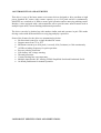
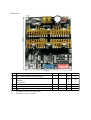
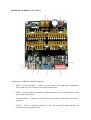
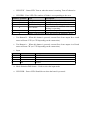
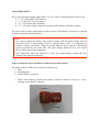
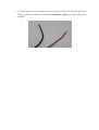
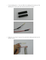
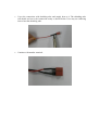
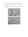
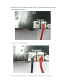
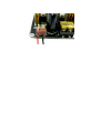
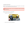
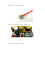
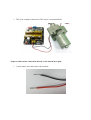
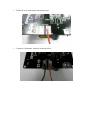
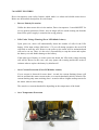
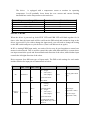
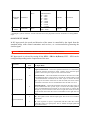
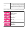
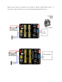
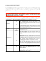
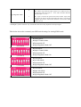
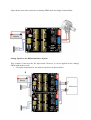
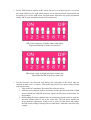
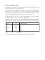
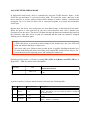
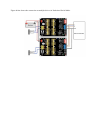
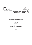
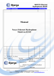
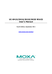
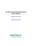
High Current DC Motor Driver Manual
1.0 INTRODUCTION AND OVERVIEW
This driver is one of the latest smart series motor drivers designed to drive medium to high
power brushed DC motor with current capacity up to 82A peak and 42A continuously.
MOSFETs are switched at 16 KHz to ensure quiet operation and no annoying whining sound.
Besides, it also equipped with a microcontroller unit to provide some smart features such as
multiple input mode, current limiting and thermal protection.
The driver can also be hooked up with another similar unit and operates in pair. This make
driving a robot with differential drive a truly plug and play experience.
Some of the features for the driver are summarized as below:
● Bi-directional control for a single brushed DC motor.
● Support motor from 7V to 25V.
● Maximum current up to 82A peak (1 second), 42A (5 minutes) or 30A continuously.
● 16 KHz switching frequency for quiet operation.
● Reverse polarity protection.
● LiPo battery low voltage warning.
● Thermal protection.
● Current limiting base on temperature.
● Multiple input modes: RC, Analog, PWM, Simplified Serial and Packetized Serial.
● On board push button for manual operation.
3.0 PRODUCT SPECIFICATION AND LIMITATIONS
Dimensions
No
Parameters
1 Input Voltage (Motor Supply Voltage)
IMAX (Maximum Continuous Motor Current)*
2 5 minutes
> 20 minutes
3 IPEAK – (Peak Motor Current) **
4 VIOH (Logic Input – High Level)
5 VIOL (Logic Input – Low Level)
*
**
Depends on the room temperature.
Must not exceed 1 second.
Min
7
Typical
-
Max
25
Unit
V
-
-
40
30
A
A
3
0
0
80
5.5
0.5
A
V
V
4.0 BOARD OR PRODUCT LAYOUT
Components on MDS40A and their functions:
1.
Dean T Connector (Male) – Connect to power source. For high current application,
please solder the wire directly to the pad at bottom layer.
2.
LED A – Turns on when the output A is high and output B is low. Indicates the current
flows from output A to B.
3.
Terminal Block – Connect to motor. Reverse the polarity if the motor direction is
incorrect.
4.
LED B – Turns on when the output A is low and output B is high. Indicates the
current flows from output B to A.
5.
LED STAT – Status LED. Turn on when the motor is running. Turn off otherwise.
6.
LED ERR – Error LED. The number of blinks is corresponding to the error.
Number of Blinks
Off
2
3
4
5
6
Error
No Error
Input Error
Lipo Undervoltage
Description
No error has been detected.
Invalid or no input detected.
The LiPo battery voltage is too low.
Over current is detected and current
Over Current
limiting is operating.
Over Temperature
The board temperature is too high.
MOSFET Driver Error Error detected by the MOSFET driver.
7.
Test Button B – When this button is pressed, current flows from output B to A and
motor will turn CCW (or CW depending on the connection).
8.
Test Button A – When this button is pressed, current flows from output A to B and
motor will turn CW (or CCW depending on the connection).
9.
Input
Pin No.
1
2
3
4
Pin Name
IN2
IN1
+5V
Gnd
Description
Input channel 2.
Input channel 1.
+5V output. Do not connect to another 5V source.
Ground.
10.
Mode Selection DIP Switch – Used to select the input mode.
11.
LED PWR – Power LED. Should be on when the board is powered.
5.0 POWER SUPPLY
Driver supports input voltage ranges from 7V to 25V. The recommended power sources are:
● 6 – 18 cells NiMH or NiCd battery.
● 2 – 6 cells LiPo or Li-Ion battery.
● 7V – 24V sealed lead acid battery.
● 7V – 24V power supply (Must be in parallel with a battery with same voltage).
The power source can be connected to the driver either via the Dean-T connector, or soldered
directly to the pad at the bottom layer.
NOTE:
1.If a power supply that cannot sink current is being used, the input voltage will rise
when the driver is regenerating (motor is slowing down). Thus, it is important to
connect a battery with same voltage in parallel with the power supply to absorb the
current generated by the motor. Else, the input voltage might rise to a level where
Driver will be destroyed permanently.
2.For application where the current is > 20A, it’s recommended to solder the wire
directly to the pad at bottom layer.
Steps to solder the wire to the Dean-T connector are shown below:
The items needed to solder wire to Dean-T connector are:
● Wire
● Shrinking tube
● Female Dean-T connector
1.
Before start soldering, identify the polarity of Dean-T connector. There are + and –
marking on the Dean-T connector.
2.
Cut and remove the wire insulator. If user needs to solder the wire directly from
battery to Dean-T connector, solder one terminal at a time and leave another one
wrapped.
3.
Cut the shrinking tube to ~2cm each. Slide in the shrinking tube into the wire. The
shrinking tube is used to protect the connection at the Dean-T terminal.
4.
Solder the wire to Dean-T connector. Be careful while soldering and make sure the
polarity is correct.
5.
Cover the connection with shrinking tube and supply heat to it. The shrinking tube
will shrink and cover the connection neatly as shown below. User may use soldering
iron to heat the shrinking tube.
6.
Continue with another terminal.
Steps to solder the wire directly to the pad at bottom layer are shown below:
1.
Identify the polarity of power terminal. There are + and – marking at the bottom layer
of MDS40A.
2.
Cut and remove the wire insulator. Solder one terminal at a time and leave another
one wrapped.
3.
Solder the wire to the pad at the bottom layer. Be careful while soldering and make
sure the polarity is correct.
4.
Continue with another terminal.
5.
Below is an example of power cable being soldered directly to the bottom layer.
6.0 MOTOR CONNECTION
Similar to the power supply, connection to the motor can be made either via the terminal
block, or it can be soldered directly to the bottom layer pad.
NOTE:
For application where the current is > 20A, it’s recommended to solder the wire directly to
the pad at bottom layer.
Steps to connect the motor via terminal block:
1.
Open the cover for terminal block.
2.
Remove the screw from the terminal block.
3.
Wrap the wire of DC motor around the screw.
4.
Put back the screw into terminal block and tighten the screw.
5.
Repeat step 2-4 for another wire of DC motor.
6.
This is an example connection of DC motor via terminal block.
Steps to solder motor connection directly to the bottom layer pad:
1.
Cut the motor wire and remove the insulator.
2.
Solder the wire to the pad at the bottom layer.
3.
Continue with another terminal as shown below.
7.0 SAFETY FEATURES
Driver incorporates some safety features which make it a robust and reliable motor driver.
Below are the detailed descriptions for each feature.
a.
Reverse Polarity Protection
Unlike the other motor driver in the market, Driver incorporates 2 extra MOSFET for
reverse polarity protection. Hence, user no longer will see smoke coming out from the
board if the power supply is connected at wrong polarity.
b.
LiPo Under Voltage Warning (Error LED blinks 3 times)
Upon power on, driver will automatically detect the number of cells for the LiPo
battery. If the input voltage falls below 3.3V per cell during operation, the error LED
will blink to warn the user. However, the power to the motor will be maintained and
will not be cut out. Thus, it is the user’s responsibility to stop the motor and replace
the battery to avoid further damage to the battery.
If the other type of battery is used to power the board, the LiPo under voltage warning
will still be shown. In this case, user may ignore the warning and he/she needs to
estimate when to replace the battery by him/herself.
c.
Over Current Protection (Error LED blinks 4 times)
If over current is detected for more than 1 second, the current limiting feature will
kick in and limit the motor current to the over current threshold (40A by default). The
current limiting only starts working after 1 second to allow a higher startup current for
the motor when it starts running.
The actual over current threshold is depending on the temperature of the board.
d.
Over Temperature Protection
The driver
is equipped with a temperature sensor to monitor its operating
temperature. It will gradually lower down the over current and current limiting
threshold base on the temperature as shown below:
Temperature Range (oC)
< 110
110 – 120
120 – 130
130 – 140
> 140
Over Current Threshold (A)
40
35
30
25
20
8.0 INPUT MODE
When the driver is powered up, both STAT LED and ERR LED will blink together for 10
times. After that, the input mode will be read from the DIP switch and retained as long as the
driver is powered. If you wish to change the input mode, you will need to change the setting
on the DIP switch and power cycle the driver (Turn it off and turn it on again).
In RC or Analog/PWM Input mode, two units of driver may be used together to control two
motors in mixed mode. This is useful to control the robot with differential drive system where
one input controls the speed and forward/backward direction of the robot, while another input
controls the left/right direction of the robot.
Driver supports four different types of input mode. The DIP switch settings for each mode
and the function for input pin are summarized as below:
Input Mode
RC
Analog /
PWM
DIP Switch
DIP Switch Description
(SW1 - SW4) (SW5 - SW8)
SW5:6
Single/Mix Mode
0X - Single
10 - Mix (Left)*
11 - Mix (Right)*
0000XXXX
SW7
Exponential Mode
SW8
SW1:2
MCU Mode
Analog/PWM Mode
00 - Analog
11 - PWM
SW5:6
Single/Mix Mode
0X - Single
10 - Mix (Left)*
11 - Mix (Right)*
XX01XXXX
SW7
Exponential Mode
SW8
Sign-Magnitude Mode
(Single Mode only). SW2
must be 0.
Input 1
Input 2
Speed
Steering (Mix Mode
only)
Speed
Speed (SignMagnitude is OFF)
Direction (SignMagnitude is ON)
SW5
N/A
SW6:8
UART Baud Rate
000 - 1200
001 - 2400
UART Rx
010 - 4800
011 - 9600
100 - 19200
101 - 38400
110 - 57600
111 - 115200
UART Slave Address UART Rx
(0x00 – 0x0f)
Simplified 0010XXXX
Serial
Packetized 0011XXXX
Serial
SW5:8
Slave Select
N/A
0 – OFF
1 – ON
X – Don’t Care
* Left/Right is just for reference. Actual side of the motor may depends on the RC transmitter or analog/PWM
input.
8.1 RC INPUT MODE
In RC input mode, the speed and direction of the motor is controlled by the signal from the
standard hobby radio control transmitter and receiver, or a microcontroller generating the
similar signal.
NOTE: The RC transmitter must be turn on before power up the driver.
RC Input mode is selected by setting all the SW1 – SW4 to 0 (Down). SW5 – SW8 can be
configured depending on the requirement of the user.
Input Mode
SW1:SW4
0000
RC Input Mode
SW5:SW6
0X
Single Channel Mode – The motor speed and direction are controlled by
a single RC channel connected to Input 1. Motor stops when the input
signal is at the center point. Input 2 is not used in this mode.
10
Single/Mix Mode
11
SW7
0
Exponential Mode
1
Left Mix Mode* – This mode should be selected for the left motor of the
robot differential drive system. Input 1 controls the overall speed as well
as forward/backward movement of the robot. Input 2 controls the left/
right or pivot movement of the robot. In left mix mode, the motor will be
slowed down when the robot is commanded to turn left and vice versa.
Right Mix Mode* – This mode should be selected for the right motor of
the robot differential drive system. Input 1 controls the overall speed as
well as forward/backward movement of the robot. Input 2 controls the
left/right or pivot movement of the robot. In right mix mode, the motor
will be slowed down when the robot is commanded to turn right and vice
versa.
Off – The speed is linear with the input signal. This is for low to medium
speed motor.
On –The response to input is exponential and this soften the control
around the center zero speed point. This is suitable for high speed and
very sensitive motor.
SW8
0
MCU Mode
1
Off – The center point will be calibrated upon power up. Timeout occurs
after lost of signal for 100ms and the motor will be stopped for safety
purpose.
On – The center point is fixed at 1.5ms and the timeout feature is
disabled. Motor will continue to run with previous speed if new signal is
not detected. This is useful when a microcontroller is used to control the
motor. The microcontroller does not need to send the pulse continuously
to the driver. Instead, it only needs to send a single pulse when the speed
or direction of the motor needs to be changed.
0 – OFF
1 – ON
X – Don’t Care
* Left/Right is just for reference only. Actual side of the motor may depends on the RC transmitter.Table
below shows the commonly used DIP switch settings for RC mode.
DIP Switch
(00000000)
(00000010)
(00001000)
(00001100)
Mode
●RC Mode
●Single Channel Mode
●Exponential Off
●MCU Mode Off
●RC Mode
●Single Channel Mode
●Exponential On
●MCU Mode Off
●RC Mode
●Left Mix Mode
●Exponential Off
●MCU Mode Off
●RC Mode
●Right Mix Mode
●Exponential Off
●MCU Mode Off
Figures below show the connection in RC mode for Single Channel Mode. Input 1 is
connected to either a RC Receiver or a microcontroller generating the RC pulse.
8.2 ANALOG/PWM INPUT MODE
In Analog/PWM input mode, the speed and direction of the motor is controlled by the analog
voltage or PWM signal. The valid input range is 0 – 5V and it’s very easy to control by using
a potentiometer. For example, the motor can be controlled by a joystick or foot pedal with
potentiometer.
NOTE: The Analog/PWM signal to stop the motor (2.5V if Sign-Magnitude mode is off,
0V otherwise) must be available when the driver is turned on. Else, the driver will show
Input Error until the correct signal is available.
Analog/PWM input mode is selected by setting SW3 to 0 (Down) and SW4 to 1 (Up). SW1
– SW2 and SW5 – SW8 can be configured depending on the requirement of the user.
SW1:SW2
00
PWM Mode
Input Mode
11
SW3:SW4
01
SW5:SW6
0X
On - The input is PWM signal. The filter capacitor is connected
and the input signal is low pass filtered to be an analog signal.
SW1 is for Input 1 while SW2 is for Input 2. SW2 must be set to 0
if Sign-Magnitude mode is turned on.
Analog/PWM Input Mode.
Single Channel Mode - The motor speed and direction are
controlled by a single channel connected to Input 1. Motor stops
when the input signal is at the center point. Input 2 is not used in
this mode.
10
Left Mix Mode* - This mode should be selected for the left motor
of the robot differential drive system. Input 1 controls the overall
speed as well as forward/backward movement of the robot. Input 2
controls the left/right or pivot movement of the robot. In left mix
mode, the motor will be slowed down when the robot is
commanded to turn left and vice versa. SW8 must be set to 0.
11
Right Mix Mode* - This mode should be selected for the right
motor of the robot differential drive system. Input 1 controls the
overall speed as well as forward/backward movement of the robot.
Input 2 controls the left/right or pivot movement of the robot. In
right mix mode, the motor will be slowed down when the robot is
commanded to turn right and vice versa. SW8 must be set to 0.
Single/Mix Mode
SW7
0
Exponential Mode
Off - The input is analog signal. The filter capacitor is not
connected and the input signal is not filtered. SW1 is for Input 1
while SW2 is for Input 2.
1
Off – The speed is linear with the input signal. This is for low to
medium speed motor.
On –The response to input is exponential and this soften the
control around the center zero speed point. This is suitable for
high speed and very sensitive motor.
SW8
0
Sign-Magnitude Mode
1
Off – Motor stops when the input signal is 2.5V. Motor moves in
one direction when the input is < 2.5V and in another direction
when the input is > 2.5V.
On – Input 1 controls the speed of the motor. Motor stops when
the input is 0V and run at full speed when the input is 5V. Input 2
is digital input and it controls the direction of the motor. SW2
must be set to 0.
0 - OFF
1 - ON
X - Don’t Care
* Left/Right is just for reference only. Actual side of the motor may depends on the Input signal.
Table below shows the commonly used DIP switch settings for Analog/PWM mode.
DIP Switch
(00010000)
(10010001)
(11011000)
(11011100)
Mode
●Analog Mode
●Single Channel Mode
●Exponential Off
●Sign-Magnitude Mode Off
●PWM Mode
●Single Channel Mode
●Exponential Off
●Sign-Magnitude Mode On
●PWM Mode
●Left Mix Mode
●Exponential Off
●Sign-Magnitude Mode Off
●PWM Mode
●Right Mix Mode
●Exponential Off
●Sign-Magnitude Mode Off
Figure below shows the connection of Analog/PWM mode for Single Channel Mode
Setting Up Driver for Differential Drive System
This example is based on the RC input mode. However, it can be applied for the Analog/
PWM input mode as well.
1. Set up the connection for two units of the driver as shown below.
2.
Set the DIP Switch to operate in RC mode. Driver for left motor must be set as left
mix mode and driver for right motor must be set as right mix mode. Exponential can
be turned on or off for both motor, but both motor must have the same exponential
setting. MCU mode should be turned off for both motor.
DIP switch setting for Left Mix Mode (00001000).
Exponential and MCU Mode are turned off.
DIP switch setting for Right Mix Mode (00001100).
Exponential and MCU Mode are turned off.
3.
For the first time, the direction and mixing side (left/right) of the motor must be
checked to make sure it is correct. Follow the steps below to set up the motor mixing
side and direction:
i. Turn on the RC transmitter first and followed by the driver.
ii. Push the speed channel stick to maximum forward position and hold it. Both
motors should run with full speed now. Ignore the direction of the motors for
the moment.
iii. Still holding the speed channel stick in maximum forward position, push the
direction channel stick to left at the same time. The left motor should run
slower than the right motor. If this is not so, power off the driver and change
the DIP switch setting of mixing side for both motor. After that, start from step
1 again.
Push the direction channel stick to right. The right motor should run slower
than the left motor. This means the mixing side of the motor is set correctly.
v. Now, we want to make sure the motor direction is correct. Push the speed
channel stick to maximum forward position and center the direction channel
stick. Both motor should run in the forward direction. If this is not so, reverse
the polarity of the motor connection.
vi. Push the speed channel stick to maximum backward position and center the
direction channel stick. Both motor should run in the backward direction. This
means the motors are running in the correct direction and the setting process
has been completed.
iv.
8.3 SIMPLIFIED SERIAL MODE
In Simplified Serial mode, driver is controlled by using the UART interface. Input 1 is the
UART Rx pin and Input 2 is the Slave Select pin.
The Slave Select must be HIGH in order for the driver to receive the UART command. If the
Slave Select pin is set to LOW, all the UART data will be ignored. This feature allows
multiple driver to be connected together to a single microcontroller UART port. The Slave
Select pin is internally pulled high and it may be left unconnected if not used.
A single byte of data is all you need to control the speed and direction of the motor. Sending
byte 127 stops the motor, 0 is full reverse and 255 is full forward.
Simplified Serial mode is selected by setting SW1, SW2 and SW4 to 0 (Down) and SW3 to
1 (Up). SW5 is not used in this mode and SW6 – SW8 are used to select the UART baud rate.
Input Mode
SW1 - SW4
0010
UART Baud Rate
SW6 - SW8
000
001
010
011
100
101
110
111
0 - OFF
1 - ON
Simplified Serial Mode
Baud Rate
1200
2400
4800
9600
19200
38400
57600
115200
X - Don’t Care
Figure below shows the connection to multiple driver in Simplified Serial Mode.
8.4 PACKETIZED SERIALMODE
In Packetized Serial mode, driver is controlled by using the UART interface. Input 1 is the
UART Rx pin and Input 2 is not used in this mode. To control the motor, data sent to the
driver must be in 4 bytes packet format which includes a header, address, command and
checksum. Up to 16 units of driver can be connected together to a single microcontroller
UART port.
Besides that, the driver also incorporates an Auto-Baud feature in Packetized Serial mode.
When the driver is first powered up, the host microcontroller must send a header byte
(Decimal 85) to the driver. The driver will then calculate the baud rate automatically based on
this character. After that, driver is ready for command and the baud rate cannot be changed
without power off and on again.
NOTE:
1.When the driver is powered up and waiting for the header byte, the error LED will
blink and indicate that there is input error.
2. driver may take up to 500ms to start up after power is applied. Sending the header byte
for auto baud during this time period may cause undesirable results. Please allow a onesecond delay between applying power and sending the header byte.
Packetized Serial mode is selected by setting SW1, SW2 to 0 (Down) and SW3, SW4 to 1
(Up). SW5 – SW8 are used to select the address.
Input Mode
SW1 - SW4
0011
Packetized Serial Mode
UART Address
SW5 - SW8
0000 - 1111
0 - 15
0 - OFF
1 - ON
X - Don’t Care
A packet consists of 4 bytes and the format is shown in the following table.
Byte
1
Name
Header
Value (Decimal)
85
2
Address
0 - 15
3
Command
0 – 255
4
Checksum
0 – 255
Description
To indicate the start of packet.
Used to identify the driver when multiple units are connected
together. The address byte must match the address configured
with the DIP switch.
Value 127 stops the motor, 0 is full reverse and 255 is full
forward.
The value for checksum must be the result of
Header + Address + Command
Figure below shows the connection to multiple drivers in Packetized Serial Mode.