1
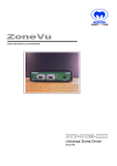
ZVS-SSI-48 INSTALLATION MANUAL.DOCX MEYERTECH LIMITED Zebra Court White Moss View Greenside Way Manchester M24 1UN Tel: +44 (0)161 643 7956 Fax: +44 (0)161 643 3992 Email:[email protected] http://www.meyertech.co.uk ZONEVU ZVS-SSI-48 INSTALLATION MANUAL Issue 2 Firmware v1.3.1.0 Issue 2 Page 1 ZVS-SSI-48 INSTALLATION MANUAL.DOCX Contents Contents .......................................................................................................................................... 2 Introduction ...................................................................................................................................... 3 What is a ZVS-SSI-48 .................................................................................................................. 3 Connections ..................................................................................................................................... 4 ZoneVu Comms ........................................................................................................................... 4 Peripheral Comms........................................................................................................................ 4 DC In ............................................................................................................................................ 4 Jumper Settings ............................................................................................................................... 5 TERM ........................................................................................................................................... 5 PROG........................................................................................................................................... 5 Local Programming .......................................................................................................................... 6 Procedure..................................................................................................................................... 6 Protocol List .............................................................................................................................. 6 Remote Programming ...................................................................................................................... 8 Connections ................................................................................................................................. 8 Direct Connection ..................................................................................................................... 8 In System programming............................................................................................................ 8 Mpower ........................................................................................................................................ 9 Accessing the configuration ...................................................................................................... 9 Config Version ........................................................................................................................ 10 ZoneVu Port ........................................................................................................................... 11 Peripheral Port ........................................................................................................................ 12 Enables................................................................................................................................... 13 Cameras ................................................................................................................................. 14 Reference ...................................................................................................................................... 15 LED Codes ................................................................................................................................. 15 Test Modes ................................................................................................................................ 15 Maintenance .................................................................................................................................. 16 Returns Procedure ..................................................................................................................... 16 Disposal ......................................................................................................................................... 17 Support .......................................................................................................................................... 18 Warranty ........................................................................................................................................ 19 Issue 2 Page 2 ZVS-SSI-48 INSTALLATION MANUAL.DOCX Introduction What is a ZVS-SSI-48 The ZVS-SSI-48 is a multi-protocol serial telemetry converter. It allows different types of cameras & receivers to be controlled from a ZoneVu system. Meyertech offers a full range of telemetry converters as well as telemetry protocols embedded in system controllers. The ZVS-SSI-48 is particularly suited to camera end installations, and is often used in combination with video encoders to extend their protocol capabilities. Another common usage is where a single ZoneVu telemetry line must be split and converted into different protocols in the field. For further details or to discuss the suitability for your particular system design please contact Meyertech Sales office. The information in this manual is believed to be accurate and reliable. However, Meyertech Limited assumes no responsibility or liability for its use, or for any infringement of patents or other rights of third parties, which may result from its use. No license is granted by implication or otherwise under any patent or other rights of Meyertech. All specifications are subject to change without prior notice. MEYERTECH LIMITED are committed to continuous product development and therefore reserve the right to change specifications without notice. 2014 ALL RIGHTS RESERVED. Issue 2 Page 3 ZVS-SSI-48 INSTALLATION MANUAL.DOCX Connections ZoneVu Comms ZoneVu comms should be connected to a source of camera control telemetry such as a ZSC1000plus (ZVR port). It can operate in Simplex mode (receive only) or Duplex mode if alarm or configuration information is required from the camera. Supported modes : RS-422 and RS-485 only Pin number 1 2 3 4 5 6 Simplex Mode RxRx+ 0V n/c n/c Earth Half Duplex Rx- and TxRx+ and Tx+ 0V n/c n/c Earth Full Duplex RxRx+ 0V TxTx+ Earth Peripheral Comms Peripheral comms should be connected to a camera or Telemetry receiver. It can operate in Simplex mode (transmit only) or Duplex mode if alarm or configuration information is required from the camera. Supported modes : RS-422 and RS-485 only Pin number 1 2 3 4 5 6 Simplex Mode n/c n/c 0V Tx Tx + Earth Half Duplex Rx- and TxRx+ and Tx+ 0V n/c n/c Earth Full Duplex RxRx+ 0V TxTx+ Earth DC In Power to the converter is provided by a 12V DC mains input power cube, supplied. Pin number 1 2 Issue 2 12V DC 0V Page 4 ZVS-SSI-48 INSTALLATION MANUAL.DOCX Jumper Settings Between the DC In and ZoneVu Comms connectors are two 2-pin jumpers. Links are supplied fitted to one pin only for retention and should be fitted across both pins if required. TERM The Termination link should be fitted as required by the installation according to the following table. TERM (J2) Fitted Not-fitted ZoneVu Comms 120Ohm Termination No Termination Usage ZVS-SSI-48 is on the end of line All other installations PROG The Programming link serves several purposes during installation & testing. It is recommended that during normal operation the link is left not fitted to avoid inadvertent changes to the configuration. PROG (J1) Mode Fitted Prior to power-up Programming mode Fitted during operation Not-fitted Test mode Normal Usage Both remote & local programming are enabled Test message are transmitted Normal operation Details of the test modes are included in the Reference section at the end of this manual. Issue 2 Page 5 ZVS-SSI-48 INSTALLATION MANUAL.DOCX Local Programming Selection of the Camera protocol only is provided for by using the PROG jumper without the need for a configuration program. Procedure Step Action 1 Power off the ZVS-SSI-48 2 Fit the PROG Link Notes CPU LED flashes rapidly. 3 Power up Rx Error LED flashes protocol code. • N short flashes, then 2 sec gap • N = Protocol number 4 Remove PROG link Min. ½ Second 5 Re-fit PROG link Protocol code changes to indicate next protocol 6 Repeat until correct protocol indicated Refer to protocol list below 7 Power off & remove PROG link Protocol List Issue 2 Protocol Number 1 ZoneVu Default Baud rate /Parity 9600 8N1 2 Pelco D 9600 8N1 3 Pelco P 9600 8N1 4 Sensormatic 4800 8N1 5 Panasonic 19200 8N1 6 Forward Vision 9600 O81 7 Molynx 9600 E81 8 Synectics 38400 N81 9 Plettac 9600 E81 10 360 Vision 9600 N81 11 Diamond 9600 E81 12 VST 9600 N81 13 TIB (Tyco) 9600 E72 Protocol Name Page 6 ZVS-SSI-48 INSTALLATION MANUAL.DOCX For selection of all other settings including Baud rate, mode & camera ranges, programming must be carried out using the Mpower configuration tool. Please refer to the Remote Programming section. Issue 2 Page 7 ZVS-SSI-48 INSTALLATION MANUAL.DOCX Remote Programming Full programming of the ZVS-SSI-48 is only possible using the Mpower configuration tool. Remote Programming is achievable with or without the PROG link fitted however this may need to be fitted before power up to ensure the ZoneVu port is configured at 9600 baud, Full Duplex (Default). Connections Direct Connection Connect to the ZoneVu Comms connector directly using a RS422 converter to your PC / laptop. • Full Duplex RS422 is required. In System programming Alternatively the ZoneVu port may be connected to the ZVR port of a site controller. Programming is then possible from one of the RS232 ports on the controller. Issue 2 • Full Duplex RS422 is required. • Correct programming of the controller is required to route telemetry to the appropriate ZVR port Page 8 ZVS-SSI-48 INSTALLATION MANUAL.DOCX Mpower Installation & general operation of Mpower is covered in a separate manual, installed with the application. This section covers details of the ZVS-SSI-48 settings and their usage. Accessing the configuration From the main Mpower menu select ‘Configuration’, ‘Peripherals’, ‘ZVS-SSI-48…’ The ‘Select Unit Address’ dialogue will be displayed. Entering a Site number and Camera number (Unit address) allows a ZVS-SSI-48 to be selected during in system programming. Issue 2 • Site Number = 0, Unit Number = 0, can be used with a direct connection regardless of programming • The ZVS-SSI-48 will respond to any Camera number (Unit address) which is enabled on it. By default all Cameras up to 1024 are enabled. • If connected through a site controller, different camera numbers will be directed to different ZVR ports • Monitor number is not used Page 9 ZVS-SSI-48 INSTALLATION MANUAL.DOCX Config Version This screen confirms connection to the ZVS-SSI-48 and displays the software version information. If Response confirmed is not seen in the Status, please check the connection and use the ‘Select’ button to retry. Issue 2 Page 10 ZVS-SSI-48 INSTALLATION MANUAL.DOCX ZoneVu Port ZoneVu Port Default Configuration Baud Rate Set to match the speed of the ZoneVu site controller or other Telemetry source Options : 1200, 2400, 4800, 9600, 19200, 38400 Mode Set to match the mode of the Telemetry source and the connection type (see Connections section) Options : Simplex, Half-duplex, Full-duplex Parity Set to match the parity and bit format of the Telemetry source Options : N81, E71, O71, E81, O81 Issue 2 Page 11 ZVS-SSI-48 INSTALLATION MANUAL.DOCX Peripheral Port Peripheral Port Default Configuration Protocol Select the Protocol type of the camera. See Supported Cameras document for list of supported features & details of each protocol. Options : ZoneVu, Pelco P, Pelco D, Sensormatic, Panasonic, Forward Vision, Molynx, Synectics, Plettac, 360 Vision, Diamond, VST and TIB. Baud Rate Set to match the speed of the camera Options : 1200, 2400, 4800, 9600, 19200, 38400 Mode Set to match the mode of the camera and the connection type (see Connections section) Options : Simplex, Half-duplex, Full-duplex Parity Set to match the parity and bit format of the camera Options : N81, E71, O71, E81, O81, N72, E72, E82, N82, O72. Issue 2 Page 12 ZVS-SSI-48 INSTALLATION MANUAL.DOCX Enables Enables Default Configuration Enables allow the behaviour of the ZVS-SSI-48 to be fine-tuned. Select an option from the ‘Available Options’ list and click ‘Add’ to enable it. Extended Addressing Select the full range of camera addresses possible under the current Peripheral protocol. Deselecting this option will enforce a smaller camera range on some protocols. • Pelco P Extended Range = 255; Normal range = 32 • Molynx Extended Range = 512; Normal range = 256 • VST Extended Range = 128; Normal range = 16 Pelco – Single Speed Lens Disables variable speed lens control for Pelco Cameras. (Recommended for Pelco Spectra dome cameras). Enable 3 to Enable 20 For future use Issue 2 Page 13 ZVS-SSI-48 INSTALLATION MANUAL.DOCX Cameras Cameras Default Configuration The Cameras page allows the camera range of the ZVS-SSI-48 to be specified and also for certain cameras to be selected for alarm / status polling. Select one or more Cameras in any list and select ‘Add’ or ‘Remove’ to move them between the three lists. To select multiple cameras, hold the Ctrl key whilst selecting, press the shift key to select a range or drag the mouse over a range of cameras. Available Cameras Cameras in this list are available but not enabled on this ZVS-SSI-48 Enabled Cameras (un-polled) Cameras in this list are enabled for control through this ZVS-SSI-48 This is the default for all cameras 1 to 1024 Enabled Cameras (polled) Cameras in this list are enabled for control and will also be polled for Alarm and / or status information (dependent on protocol) Issue 2 Page 14 ZVS-SSI-48 INSTALLATION MANUAL.DOCX Reference LED Codes Status CPU LED state 1Hz Flash Rx Error LED state Off Self-test mode OK 1Hz Flash Self-test mode FAIL Programming mode 1Hz Flash 1Hz Flash (alternate with CPU) On Normal 10Hz Flash Indicates Peripheral protocol Notes Power up with PROG link not fitted Fit PROG whilst in Normal state Fail state latched until PROG link removed N short flashes followed by 2 seconds off. N = Protocol number. Test Modes Test modes are provided to assist the engineer in determining if the setup & connection to the camera is correct, and for diagnosing problems. To enter test mode, power on the converter in normal mode (PROG link not fitted), then fit the PROG link: • Test Mode 1 starts immediately the link is fitted • Removing the Link stops the test • Re-fitting the link selects the next test mode (1 -> 2 -> 3 -> 4 -> 5 -> 1….) Test Mode 1 Test Detail Result Pan Left Cameras Pan * 2 Pan Right 3 Stop 4 Full Duplex Loop-back Command sent to each enabled camera in turn, 1 per second Command sent to each enabled camera in turn, 1 per second Command sent to each enabled camera in turn, 1 per second Test message send alternately between ZoneVu & Peripheral ports 5 Half Duplex Loop-back Test message send alternately between ZoneVu & Peripheral ports Cameras Pan * Cameras Stop Rx Error LED stays on if message not received Rx Error LED stays on if message not received * Note : The length of the time a camera moves for, in response to a single command will vary between different camera types. A ZoneVu camera will typically move for 1 second during this test. Issue 2 Page 15 ZVS-SSI-48 INSTALLATION MANUAL.DOCX Maintenance The ZVS-SSI requires no Planned Preventive Maintenance periods (PPM’s) as it is mainly solid state in design. The ZVS-SSI contains no serviceable parts and should be returned to our Service Centre in Scunthorpe for repair or replacement under warranty. Any repairs, attempted repairs or replaced components not carried out by the Meyertech Service Centre will void all Meyertech warranties and liabilities. If your ZVS-SSI has to be returned to our Service Centre please follow the returns procedure below, otherwise delays may be incurred in returning or replacing the ZVS-SSI. Returns Procedure Prior to returning your ZVS-SSI. 1. Contact our Service Centre by phone on 0161 643 7956 or by email [email protected] for a Goods Return Number. 2. The GRN will be logged by our staff along with the reported problem. 3. Pack the ZVS-SSI into the original packing it was delivered in. Failure to do so means the unit may incur further damage in transit, which Meyertech cannot be responsible for. 4. Organise delivery of the ZVS-SSI back to our Service Centre in Scunthorpe. Use a reputable carrier, as again Meyertech cannot accept liability for loss of goods in-transit. 5. On receiving the ZVS-SSI our staff will, after initial examination advise of the course of action we intend to take. a. Repair the ZVS-SSI under warranty. The ZVS-SSI will be repaired and returned to you free of charge. b. Replace the ZVS-SSI under warranty. The ZVS-SSI will be repaired and returned to you free of charge. c. Repair the ZVS-SSI at a quoted cost. An official purchase order to cover the cost and return of the product will be required prior to commencement of repair. d. Advise you that the ZVS-SSI is not repairable. You can then decide to have the product returned to you at the standard delivery charge or we can dispose of the product free of charge. Meyertech Service Centre Unit 18 Queensway Business Centre Dunlop Way Scunthorpe DN16 3RN Tel: 01724 278833 Fax: 01724 289099 Issue 2 Page 16 ZVS-SSI-48 INSTALLATION MANUAL.DOCX Disposal There are no additional requirements beyond safe working practice in the decommissioning of the Meyertech ZVS-SSI. However the ZVS-SSI contains printed circuit boards populated with electronic components. The whole unit must be returned to Meyertech Service Centre for final disposal. Please follow the normal returns procedure. Issue 2 Page 17 ZVS-SSI-48 INSTALLATION MANUAL.DOCX Support At Meyertech our staff understand quality support is important to you, vital in fact, which is why we place such a high precedence on providing it. For all matters relating to support go to our website to find the information you require. Please visit http://www.meyertech.co.uk/support.html. MEYERTECH LIMITED Zebra Court White Moss View Greenside Way Manchester M24 1UN Tel: +44 (0)161 643 7956 Fax: +44 (0)161 643 3992 Email: [email protected] http://www.meyertech.co.uk Issue 2 Page 18 ZVS-SSI-48 INSTALLATION MANUAL.DOCX Warranty Please refer to Meyertech Limited ‘Terms & Conditions of Sale of Goods & Services’ for interpretation. 1. If the Buyer establishes to the Seller's reasonable satisfaction that there is a defect in the materials or workmanship of the Goods manufactured, then the Seller shall at its option, at its sole discretion and within a reasonable time, a. arrange for the repair or making good such defect or failure in such Goods free of charge to the Buyer (including all costs of transportation of any Goods or materials to and from the Buyer for that purpose), b. replace such Goods with Goods which are in all respects in accordance with the Contract, or subject, in every case, to the remaining provisions of this Condition 1 provided that the liability of the Seller under this Condition 1 shall in no event exceed the purchase price of such Goods and performance of anyone of the above options shall constitute an entire discharge of the Seller's liability under this warranty. 2. Condition 1 shall not apply unless the Buyer: a. b. notifies the Seller in writing of the alleged defect within 12 (twelve) months from delivery or such other period or periods as may be agreed in writing between the Seller and the Buyer, and allows the Seller a reasonable opportunity to inspect the relevant Goods. 3. For the avoidance of doubt, the Seller shall be under no liability under the warranty in Condition 1 above: a. where such defects arise from any drawing, design or specification supplied by the Buyer; or b. where such defects arise from fair wear and tear, wilful damage, or negligence of a party other than the Seller (or its employees or authorised personnel), abnormal working conditions, failure to follow the Seller's instructions (whether oral or in writing), misuse or alteration or repair of the Goods without the Seller's approval; or c. where such defects arise in parts, materials or equipment which have not been manufactured or designed by the Seller but have been purchased at the Buyer's request by the Seller from the Buyer's designer and manufacturer or from some other third party (the “Third Party Supplier”). d. if the total price of the Goods has not been paid by the due date for payment e. in respect of any type of defect, damage or wear specifically excluded by the Seller by notice in writing: or f. if the Buyer makes any further use of the Goods after giving notice in accordance with Clause 1 4. Any repaired or replaced Goods shall be redelivered to the Buyer free of charge to the original point of delivery but otherwise in accordance with and subject to these Conditions. 5. Alternatively to Condition 1 the Seller shall be entitled at its absolute discretion on return of the defective Goods to the Seller (at the Seller's request) to refund the price of the defective Goods in the event that such price shall already have been paid by the Buyer to the Seller, or, if such price has not been paid, to relieve the Buyer of all obligation to pay the sum by the issue of a credit note in favour of the Buyer in the amount of such price. 6. In respect of all Goods supplied to the Seller by a Third Party Supplier the Seller will on request pass on to the Buyer (in so far as reasonably possible) the benefit of any warranty given to the Seller by such Third Party Supplier and will (on request) supply to the Buyer details of the terms and conditions of such warranty and copies of any relevant product information sheets, technical data sheets or product leaflets issued by such Third Party Supplier and the Buyer shall be solely responsible to the entire exclusion of the Seller for complying with the same. 7. For the purposes of Condition 1 references to Goods shall be deemed to exclude software. 8. The Buyer acknowledges that software in general is not error-free and agrees that the existence of such errors in the Software Programs shall not constitute a breach of this Contract. 9. In the event that the Buyer discovers a material error which results in the Programmed Products not performing substantially in accordance with the Functional Specification, or the Licensed Programs not performing substantially in accordance with the relevant Program Documentation and notifies the Seller of the error within 90 days from the date of the Seller making available the respective software to the Buyer (the `warranty period") the Seller shall at its sole option either refund the price which the Buyer has paid to the Seller (or if such price has not been paid, relieve the Buyer of all obligations to pay the sum) in respect of the respective software or use all reasonable endeavours to correct by patch or new release (at its option) that part of the software which does not so comply provided that such non-compliance has not been caused by any modification, variation or addition to the software not performed by the Seller or caused by its incorrect use, abuse or corruption of the software by use of the software with other software or on equipment with which it is incompatible, 10. To the extent permitted by English law, the Seller disclaims all other warranties, with respect to the software which it provides pursuant to the Contract, either express or implied, including but not limited to any implied warranties of satisfactory quality or fitness for any particular purpose. 11. The Buyer is solely responsible for various scanning the software that it receives from the Seller pursuant to the Contract. 12. The Seller warrants that it will use reasonable skill and care in providing the Services to the buyer Issue 2 Page 19