1
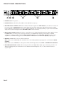
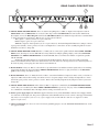
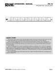
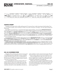
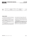
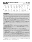
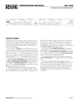
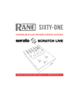
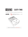
OPERATORS MANUAL
SM 26B
SPLITTER MIXER
QUICK START
Realizing that in most areas there are laws against reading owners manuals, and that reading them under the blankets at
night with a flashlight makes you feel stupid, we therefore provide this brief, yet informative, description of how to use the
SM 26B just in case your batteries are low and your mother is about to come in the room.
To achieve a quick understanding of the SM 26B, think of it as a six channel mixer with faders and pans only. Or think
of it as a 2-to-6 channel splitter with output level controls and a mix knob (to control how much of which input goes to
which output). If you get that, you may stop here as long as you know how to hook up the power supply.
As a six channel mixer, MONO IN 1 through 6 may be placed on the Right or Left bus or both, in any amount. The
respective LEVEL knobs on the front of the unit serve as the mixer’s faders, the adjacent PAN controls place the channel’s
signal into the stereo field. As an effects mixer or line level expander for a larger mixer, set up the LEVELS and adjust the
PANS. The MASTER OUTPUT LEVEL adjusts the overall level of the mix at the Master Outputs.
As a splitter, place one or both input signals into the LEFT and/or RIGHT Inputs. Select the Input(s) to be placed at
each of the six MONO OUTs by rotating the MIX/PAN control to the proper position. Set the individual CHANNEL
LEVEL controls for proper output level. The MASTER INPUT LEVEL control on the front adjusts both Right and Left
Input signal levels together.
Never connect anthing except an RS 1 or other approved Rane AC power supply to the red thing that looks like a
telephone jack on the rear of the SM 26B. This is an AC input and requires some special attention if you do not have an
operational power supply exactly like the one that was originally packed with your unit. See the full explanation of the
power supply requirements elsewhere in this manual.
SM 26B CONNECTION
When connecting the SM 26B to other components in
your system for the first time, leave the power supply for last.
This gives you a chance to make mistakes and correct them
before damage is done to anything fragile.
As you have no doubt noticed, all Inputs and Outputs on
the SM 26B’s rear panel are ¼" connectors. The Inputs and
Outputs are active balanced on Tip-Ring-Sleeve (TRS) jacks
which allow the flexibility of connecting in either a balanced
or unbalanced fashion. If unbalanced operation is your
preference, the simplest way to accomplish this is through the
use of tip and sleeve ¼" connectors. The ring is not essential
unless balanced operation is required. You should be aware
that if you are running unbalanced and using TRS connectors
with both ring and tip, the ring and sleeve must be shorted
together. Failure to do so on the inputs results in a gain loss of
6 dB.
Balanced operation requires that TRS plugs be used. The
tip is hot (+), the ring is return (–) and the sleeve is ground.
RaneNote 110, “Sound System Interconnection” (included
here) contains some great pictures to aid your interconnect
ventures.
Manual-1
FRONT PANEL DESCRIPTION
1. POWER switch. Two guesses ......
2. POWER indicator. When this yellow LED is lit, the SM 26B is ready to go.
3. MASTER OUTPUT LEVEL control. This controls the amount of signal at the MIX OUTPUT jacks. It does not affect the
level of any of the six MONO OUTs. This control changes the gain of the output stages. This allows an increase in headroom to eliminate overloading due to excessive combined signal from one or more Inputs. Range of gain is from Off to 0dB
(unity). Refer to the block diagram in the SM 26B Data Sheet and/or schematics.
4. MONO INPUT LEVEL control. Each of these controls the Level of signal through that particular channel. When fed from
the MONO IN jack, each stage has a gain range from Off to +12 dB minimum, allowing level matching of -10 dBV
equipment to +4 dBu gear. When fed via the LEFT & RIGHT INPUT(s), these CHANNEL LEVEL controls automatically limit to a maximum of unity gain to accommodate the +12dB available from the Left & Right Input gain stages.
5. MIX/PAN controls. These serve two different functions:
MIX: When used as a SPLITTER, this controls the mix of Left and Right Master Input program to each Channel’s MONO
OUTPUT.
PAN: When used as a MIXER, this control pans the Mono Channel Input between the LEFT and RIGHT MIX OUTPUTS.
6. MASTER INPUT LEVEL control. This sets the gain of the Left & Right Master Input stages, with a range of Off to +12
dB. In the splitting mode, this controls the Level of all Mono Channel Outputs at once (i.e., those which do not have a
separate input).
Manual-2
REAR PANEL DESCRIPTION
1. LEFT & RIGHT MASTER INPUTS. These are balanced Tip-Ring-Sleeve (TRS) ¼" Inputs. These Inputs feed all six
MONO OUTs when all MONO INs are not used. Connecting to individual MONO INs disconnects that channel from
these Inputs (refer to the Block Diagram found on the SM 26B Data Sheet). For unbalanced operation use a standard mono
¼" plug; for balanced operation use a TRS (stereo) ¼" plug wired as follows:
TIP is signal + (connect to Pin 2 on a 3-pin connector).
RING is signal - (pin 3 in a 3-pin connector).
SLEEVE is signal or chassis ground (case on a 3-pin connector). An internal Input Sheild Reference jumper connects
signal ground (default), chassis ground, or neither to all Input Sleeve connections. See the assembly diagram for location
should the need arise to change this.
2. LEFT & RIGHT EXPAND OUTPUTS. These ¼" TRS jacks are connected in parallel with the Master LEFT & RIGHT
INPUT jacks, allowing two or more SM 26Bs to be daisychained for multiple splitting. Simply connect these EXPAND
OUTPUTS to the LEFT & RIGHT INPUTs of another SM 26B; there is no limit to the number of expansions possible
with the SM 26B.
NOTE: These Expand Outputs are not buffered from the Master Inputs. Therefore it is not possible to mix both
balanced and unbalanced lines in the same channel between several units: once the ring and sleeve are shorted anywhere in
the chain (by using a mono plug) the entire line becomes unbalanced.
3. MONO INPUTS. These are TRS ¼" jacks which accept either balanced or unbalanced mono signals. These are switching
jacks which automatically bypass the Master LEFT & RIGHT INPUTs whenever a plug is inserted (see the Block Diagram). Follow wiring conventions as in #1.
4. MONO OUTPUTS. These ¼" TRS jacks deliver either a conventional unbalanced output (use mono cords), or a balanced
output (use TRS cords). Follow wiring conventions as in #1. A separate jumper exists to change all Output Sleeve connections from signal ground, chassis ground, or neither. Refer to the assembly diagram for the jumper location if you need to
change this.
5. LEFT & RIGHT MIX OUTPUTS. These balanced TRS ¼" outputs are controlled by the MASTER OUTPUT LEVEL
control. They are fed either by the Master LEFT & RIGHT INPUTS (respectively) or by any of the six MONO INPUTS,
or a combination of both (Rane Note 108 helps). Follow wiring conventions as in #1.
6. Remote power supply input. The SM 26B is supplied from the factory with a Model RS 1 Remote Power Supply suitable
for connection to this input jack. The power requirements of the SM 26B call for a 18-24 volt AC center-tapped transformer
only. This is not a telephone jack. Never use a power supply with your SM 26B other than the one supplied or a Rane
approved replacement.
7. Chassis ground point. A 6-32 screw is used for chassis grounding purposes. See the CHASSIS GROUNDING note on the
next page for details.
Manual-3
OPERATING INSTRUCTIONS
Since numerous applications exist for the SM 26B, no
single set of operational procedures control its use. Rane Note
108 (included) explores the many configurations of the
SM 26B in depth, and you should peruse it for applications
information.
INTERNAL JUMPER OPTIONS
There exist within the SM 26B some signal routing
options, requiring removal of the top cover to move some
jumpers.
If an SM 26B needs to have an additional set of independent outputs, as in a 2x4 stereo distribution amplifier (see
Rane Note 108, Figure 10), the LEFT and RIGHT MIX
OUTPUTS can be used in addition to the 6 MONO OUTS.
Normally, the LEFT and RIGHT MIX OUTPUTS produce
the sum mix of all 6 LEVEL and PAN controls. To break any
Channel away from the Mix Output bus, jumpers have been
provided. Jumper 1W2 connects MONO OUT 1 to the mix
bus. 2W2 connects MONO OUT 2, 3W2 connects MONO
OUT 3, and so on.
POWER SUPPLY
As noted elsewhere in this manual, never use a power
supply with your SM 26B other than the one supplied with
your unit or an exact replacement obtained from Rane
Corporation. The SM 26B’s power supply is an AC supply,
which is a 18 - 24 volt center tapped transformer capable of
supplying the current demanded by this product. Using any
other type of supply may damage the mixer and void the
warranty.
IMPORTANT NOTE
CHASSIS GROUNDING
If after hooking up your system it exhibits excessive
hum or buzzing, there is an incompatibility in the grounding configuration between units somewhere. Your
mission, should you accept it, is to discover how your
particular system wants to be grounded. Here are some
things to try:
1. Try combinations of lifting grounds on units that
are supplied with ground lift switches or links.
2. If your equipment is in a rack, verify that all chassis
are tied to a good earth ground, either through the line
cord grounding pin or the rack screws to another
grounded chassis.
3. Units with outboard power supplies, such as the SM
26, do not ground the chassis through the line cord. Make
sure that these units are grounded either to another chassis
which is earth grounded, or directly to the grounding
screw on an AC outlet cover by means of a wire connected to a screw on the chassis with a star washer to
guarantee proper contact.
Please refer to RaneNote 110, “Sound System Interconnection” in this manual for further information on
system grounding.
©Rane Corporation 10802 47th Ave. W., Mukilteo WA 98275-5098 TEL (425)-355-6000 FAX (425)-347-7757 WEB http://www.rane.com
All features & specifications subject to change without notice. FEB98
Manual-4