1
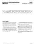
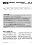
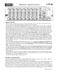
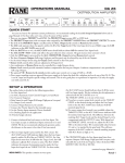
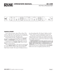
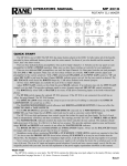
OPERATORS MANUAL
DC 24
DYNAMIC CONTROLLER
GATE / EXPANDER
POWER
-20
-30
-10
0
4 5 6
10
THRESHOLD
COMPRESSOR
7
8
2
-40
-50
3
1
10
(:1)
RATIO
-20 -10 0
-30
10
20
THRESHOLD
1
10
(:1)
RATIO
0
3
0
-6
+6
-20
+20
THRESHOLD
CH 1 OUTPUT
LOW
0
6
12
4
1.1
-40
-48
LIMITER
1.4 1.6 2
1.2
3
-6
BYPASS
24
GAIN
REDUCTION
+6
-12
SIG
+12
LEVEL OL
CROSSOVER
200
400
150
800
125
1.2k
2k
MODE 100
4k
90
6k
75
70
7k
DUAL
SLAVE
FREQUENCY
GATE / EXPANDER
-20
-30
-10
0
4 5 6
10
THRESHOLD
COMPRESSOR
7
8
2
-40
-50
3
1
10
(:1)
RATIO
-20 -10 0
-30
10
20
THRESHOLD
1
10
(:1)
RATIO
0
3
0
-6
+6
-20
+20
THRESHOLD
CH 2 OUTPUT
HIGH
0
-6
6
12
4
1.1
-40
-48
LIMITER
1.4 1.6 2
1.2
3
DC 24
DYNAMIC
CONTROLLER
24
GAIN
REDUCTION
+6
BYPASS
-12
SIG
+12
LEVEL OL
QUICK START
Shredded, this document makes excellent packing material. In its present form, it makes interesting and useful reading. If you
run out of patience quickly, at least read this part to make sure you don’t exterminate everything in a two mile radius by doing something wrong.
In a nutshell, to use the DC 24 as a conventional dual channel compressor/limiter, ensure that the CROSSOVER ENGAGE
switch on the rear is in its out position. Attach one or two channels of inputs and outputs to the respective connectors on the rear.
With all RATIOS down, LIMITER THRESHOLD all the way up and the LEVEL controls in center-detent you have an expensive
patch cord. Make sure the BYPASS switches are out and set the GATE and COMPRESSOR for the desired ratios and thresholds.
Turning the LIMITER THRESHOLD down decreases the level at which limiting occurs. The GATES and COMPRESSORS may
both be activated by the source material applied to Channel 1 if the DUAL/SLAVE switch is pressed in. This is a normal condition
for true stereo program material.
To use the DC 24 's crossover bandsplit mode, be sure the rear panel CROSSOVER ENGAGE switch is in. Connect the input to
CH 1/CROSSOVER IN. With the rear panel OUTPUTS switch set to SEPARATE, split outputs are available at the CH 1/LOW
OUT and CH 2/HIGH/COMBINE OUT jacks. With the OUTPUTS switch at COMBINE, use only the CH 2/HIGH/COMBINE OUT jack for a mono sum of high and low channels.
NEVER CONNECT ANYTHING EXCEPT AN RS 1 OR OTHER APPROVED RANE AC POWER SUPPLY TO THE
THING THAT LOOKS LIKE A TELEPHONE JACK ON THE REAR OF THE DC 24. This is an AC input and requires some
special attention if you do not have an operational power supply EXACTLY like the one that was originally packed with your unit.
DC 24 CONNECTION
Placing the DC 24 within the chain of events in your system
varies slightly depending on application. If you are assembling
a sound reinforcement system, the DC 24 would typically be
placed between the equalizer (you do use one, don’t you?) and
the active crossover, or the power amplifier if passive crossovers
(or the DC 24 crossover) are used.
In recording applications, the DC 24 may be used in conjunction with insert loops on the mixing console or in series
with the outputs en route to the recorder. Most consoles allow
headphone monitoring of the processed signal if the device is
connected to the inserts. A most useful feature. If the DC 24 is
WEAR PARTS: This product contains no wear parts.
used on mixdown, it may be connected to the output of the multichannel recorder or again on inserts of the mixdown console.
Many recording situations require that the DC 24 be connected to the patch bay in the system so it may be easily moved
from one signal location to another. This call should be made
based upon the requirements of the application.
Wiring of this and all components should follow the Sound
System Interconnection RaneNote included in this manual. This
note details standard wiring conventions which should be used
to prevent noise and distortion. Also see the Chassis ground
point on page Manual-3.
Manual-1
FRONT PANEL DESCRIPTION
1
8
GATE EXPANDER
POWER
-20
-30
-10
0
-50
10
THRESHOLD
3
COMPRESSOR
7
8
2
-40
2
3
4 5 6
1
10
(:1)
RATIO
4
-20 -10 0
-30
10
-48
20
THRESHOLD
5
1
10
(:1)
RATIO
6
0
3
0
-6
+6
-20
+20
THRESHOLD
7
CH 1 OUTPUT
LOW
0
6
12
4
1.1
-40
LIMITER
1.4 1.6 2
1.2
3
10 12
-6
+6
BYPASS
24
-12
GAIN
REDUCTION
SIG
9
+12
LEVEL OL
8
CROSSOVER
400
200
150
800
125
1.2k
2k
MODE 100
90
4k
75
6k
70
7k
DUAL
FREQUENCY
SLAVE
11
13
GATE EXPANDER
-20
-30
-10
0
3
4 5 6
-50
10
THRESHOLD
3
7
8
2
-40
COMPRESSOR
1
10
(:1)
RATIO
4
-20 -10 0
-30
10
-48
20
THRESHOLD
5
1
10
(:1)
RATIO
6
0
3
0
-6
+6
-20
+20
THRESHOLD
CH 2 OUTPUT
HIGH
0
-6
6
12
4
1.1
-40
LIMITER
1.4 1.6 2
1.2
3
10
-12
SIG
9
DC 24
DYNAMIC
CONTROLLER
24
GAIN
REDUCTION
7
+6
BYPASS
+12
LEVEL OL
11
1 POWER switch: It has been a tradition at Rane Corporation to say something clever about the POWER switch on all its products. Certain government restrictions now eliminate our option of continuing this tradition. Pity.
2 POWER indicator LED: This solid-state yellow illumination device lights up to let the operator know Item 1 (above) is working
and the thing is plugged in.
3 GATE / EXPANDER THRESHOLD control: allows the operator to set the input level below which the Gate/Expander operates. The LED illuminates yellow any time the input signal falls below the threshold level set by this control.
4 GATE / EXPANDER RATIO control: determines the Ratio to be applied to the Gate/Expander function. Increased clockwise
rotation increases the circuit slope. The full counter-clockwise position disables the Gate/Expander.
5 COMPRESSOR THRESHOLD control: determines above what input level the Compressor functions. Full clockwise rotation
disables the Compressor entirely. The LED illuminates yellow any time the input signal exceeds the threshold level set by this
control.
6 COMPRESSIOR RATIO control: determines the slope of the Compressor once it has exceeded the indicated threshold. Full
counter-clockwise rotation of the RATIO control disables all Compressor activity.
7 LIMITER THRESHOLD control: determines above what level the Servo Locked Limiter™ functions. Full clockwise rotation
of this knob disables all Limiter activity. The LED illuminates red any time the input exceeds the LIMITER THRESHOLD setting.
8 GAIN REDUCTION meter: indicates the amount of reduction, below unity, being applied to the audio signal by the VCA.
9 BYPASS switch: When pressed in, this channel in the DC 24 is is hard-wire Bypassed. Each channel may be individually Bypassed for comparison and alignment purposes. See OPERATING INSTRUCTIONS on page Manual-4.
0 OUTPUT LEVEL control: increases or decreases the output gain of each channel by 12 dB. In the center detent, gain will be
unity. (NOTE: Channel 2 OUTPUT LEVEL controls overall output in COMBINE mode.)
q SIGnal present LED: illuminates any time the input signal exceeds approximately -40 dBu.
The OverLoad LED: illuminates any time the output exceeds a level equal to -4 dB below the clipping level.
w DUAL / SLAVE mode switch: In the in (SLAVE) position, this switch causes both channels’ Gate, Compressor and Limiters to
act together, i.e., they are “slaved.” All controls for both channels remain active, so independent settings are still possible; however, whenever a signal in one channel exceeds its settings, then both channels change by the same amount. In the out (DUAL)
position, both channels operate independently.
e CROSSOVER FREQUENCY control: This rotary control selects the crossover frequency. What did you think?
Manual-2
REAR PANEL DESCRIPTION
10
DC 24
INPUTS AND OUTPUTS
TIP=#2=POSITIVE
RING=#3=NEGATIVE
SLEEVE=#1=SIGNAL GROUND
POWER
TIP=SEND
RING=RETURN
TIP=SEND
RING=RETURN
OUTPUTS
CH 2 TRIM
CH 2
IN
CH 2 HIGH /
COMBINE OUT
CH 2
SIDE CHAIN
CROSSOVER
ENGAGE
8
6
3
4
5
7
SEPARATE COMBINE -10 dBV
+4 dBu
CH 1 TRIM
CH 1 /
CROSSOVER IN
CH 1 /
LOW OUT
CH 1
SIDE CHAIN
600mA
CLASS 2 EQUIPMENT
6
1
2
5
9
-10 dBV
+4 dBu
MADE IN U.S.A.
RANE CORP.
N108
1 CHANNEL 1 INPUT connectors: deliver signal to both channel 1 of the processor and to the crossover circuit. Choose either
the XLR or the ¼" TRS jack, do not use both, they do not sum.
2 CHANNEL 1 / LOW OUTPUT connectors: deliver signal from channel 1’s processing circuitry and represents the low-pass
portion of the signal when the CROSSOVER ENGAGE switch 7 is in the in position. Both the XLR and the ¼" TRS jack may
be used at the same time if desired.
3 CHANNEL 2 INPUT connectors: only deliver signal to channel 2’s processor. It is disconnected when the CROSSOVER ENGAGE switch 7 is in its in position. Choose either the XLR or the ¼" TRS jack, do not use both, they do not sum.
4 CHANNEL 2 / HIGH / COMBINE OUTPUT connectors: make the signal from channel 2 available to the outside world and
is the high-pass portion of the audio when the CROSSOVER ENGAGE switch 7 is in its in position. If the OUTPUTS switch
8 is in the COMBINE position, this output produces the sum of channels 1 & 2 and its overall level is controlled by CH 2
OUTPUT LEVEL. Both the XLR and the ¼" TRS jack may be used at the same time if desired.
5 SIDE CHAIN: Inserting a ¼" TRS plug into this jack breaks the input signal path to both the Compressor and Gate control
circuit. Inserting an equalizer in this loop enables greater compression of boosted equalizer frequencies. The standard convention
is used of Tip=Send & Ring=Return.
6 INPUT GAIN TRIM switches: In its +4 dBu position, the input gain of the respective channel is unity. In the -10 dBV position,
the input gain is increased by 12 dB (although mathematically suspicious, it really is 12 dB, not 14 dB) to compensate for certain
recording devices. This switch must be in the +4 dBu position for front panel calibration accuracy.
7 CROSSOVER ENGAGE switch: In its in position, this switch places the low pass portion of the audio signal on CH 1 /LOW
OUT, and the high pass portion on CH 2 / HIGH / COMBINE OUT.
8 SEPARATE / COMBINE OUTPUT switch: In the COMBINE mode, the outputs of channel 1 and channel 2 are added
together and delivered to the CH 2/HIGH/COMBINE OUT connector. This feature is supplied to allow an input to be split
by the crossover, high pass and low pass delivered to separate processor channels, and recombined at the output of the unit. The
COMBINE mode has no effect on the output of channel 1.
9 Remote POWER supply input: The DC 24 is supplied from the factory with a Model RS 1 Remote Power Supply suitable for
connection to this input jack. The power requirements of the DC 24 call for an 18-24 volt AC center-tapped transformer only.
This is not a telephone jack. Never use a power supply with your DC 24 other than the one supplied or an exact replacement obtained
from Rane Corporation. Using any other type of supply may damage the unit and void the warranty.
0 Chassis ground point: A #6-32 screw is used for chassis grounding purposes. If, after hooking up your system, it exhibits excessive hum or buzzing, there is an incompatibility in the grounding configuration between units somewhere. Your mission is to
discover how your particular system wants to be grounded. Here are some things to try:
1. Try combinations of lifting grounds on units that are supplied with ground lift switches or links.
2. If your equipment is in a rack, verify that all chassis are tied to a good earth ground, either through the line cord grounding pin or
the rack screws to another grounded chassis.
3. Units with outboard power supplies, such as the DC 24, do not ground the chassis through the line cord. Make sure that these
units are grounded either to another chassis which is earth grounded, or directly to the grounding screw on an AC outlet cover by
means of a wire connected to a screw on the chassis with a star washer to guarantee proper contact. If you are connecting the DC
24 outputs directly to a power amplifier, be sure to connect a ground wire to the amplifier chassis.
Refer to the “Sound System Interconnection” RaneNote (supplied with this manual) for further grounding information.
Manual-3
OPERATING INSTRUCTIONS
Once all of the inputs and outputs are properly connected in
accordance with the preceding section, normal operation of the
DC 24 should be achievable. If any of the following procedures
do not appear to produce the required results, take a step backwards and check your wiring.
PRE-FLIGHT CHECKLIST
Before proceeding, it’s a good idea to turn the control knobs
to the following positions:
1. POWER...off
2. GATE / EXPANDER THRESHOLD...full CCW
3. GATE / EXPANDER RATIO...full CCW
4. COMPRESSION THRESHOLD...full CCW
5. COMPRESSION RATIO...full CCW
6. LIMIT THRESHOLD...full CW
7. OUTPUT LEVEL...centered in its detent
8. Set all pushbuttons on the front and rear to their out positions.
9. Set the OUTPUTS slide switch to SEPARATE.
10. Set the gain TRIM switches to +4 dBu.
LIMITING
With all of the preceding accomplished, turn the POWER
switch on (be sure your amp is turned down). The DC 24 is now
nothing but a unity gain amplifier. Cycling the BYPASS switches
with audio passing through the unit should yield no difference
in level or sound dynamics. The GAIN REDUCTION meters
should indicate 0 and nothing else. Assuming your input signal
has peaks in excess of -20 dBu, you should be able to rotate the
LIMITER THRESHOLD controls CCW and see some gain
reduction occur on the meter simultaneously with a randomly
illuminating THRESHOLD LED. You should begin to hear the
difference. Leave these controls at whatever Limit level is appropriate for your application.
COMPRESSION
To use the Compressor, set the COMPRESSOR THRESHOLD for an appropriate level, you should see the associated LED
illuminate as signal goes above and below this level. The COMPRESSOR RATIO control adjusts the gain reduction slope
above the level you have set.
GATE / EXPANDER
The Gate / Expander function works similarly. If the GATE
/ EXPANDER THRESHOLD is still fully CCW, rotate the
GATE / EXPANDER RATIO to its full CW position. Stop
your audio source and you will see the GAIN REDUCTION
LEDs drop to the -24 dB position. This indicates that the Channel is in the fully gated mode. If you wish to have gating occur at
a higher level, rotate the GATE /EXPANDER THRESHOLD
control CW to a higher level. If you wish to create special effects
with this gate, you may elect to use a lower GATE / EXPANDER RATIO setting. This inhibits full gating by the amount
indicated around the control. Experiment with all the controls to
obtain the required results.
STERNO
When using the DC 24 as a true stereo (a.k.a. sterno; hey,
lighten up, it’s a joke!) processor, left channel in Channel 1 and
right channel through Channel 2, it is a good idea to operate
the unit in the SLAVE mode to prevent large balance and image
shifts. While in the SLAVE mode, both channels attenuate by
exactly the same amount when the Gate and Compressor work,
maintaining the stereo image.
ATTENTION SHOPPERS
This seems like a good place to throw in a few words of caution. The DC 24 allows a great deal of flexibility. As such, it also
allows one to come dangerously close to completely destroying
an otherwise respectable audio signal if some thought and care
is not put into the operation of the unit. There are combinations
of THRESHOLD and RATIO settings on the Gate, Expander
and Limiter which allow each to fight the others and in some
cases completely cancel. The same caution applies to any signal
processor, such as an equalizer or crossover, however these are
a bit more intuitive and less likely to be used in a destructive
manner. Just be gentle at first and you should not encounter too
much difficulty. If you become overwhelmed, go back to the
PRE-FLIGHT CHECKLIST for initial control settings and
start over.
BYPASS SWITCHES IN CROSSOVER & COMBINE MODES
Crossover Mode. Do not use the BYPASS switches when in
the CROSSOVER mode. Use of BYPASS in the crossover mode is
potentially destructive since these switches route full bandwidth
audio to drivers designed only for a limited frequency range.
(CH 2 BYPASS is automatically defeated, but Ch. 1 is still active
— do not engage the CH 1 BYPASS for any reason.)
Combine Mode. As more users (particularly bass guitar
players) discover new applications for this mode, they want to
use BYPASS as an aid in optimizing settings. Unfortunately,
the BYPASS switches do not operate in the COMBINE mode;
however, a simple trick solves the problem:
1. Permanently engage the CH 1 BYPASS switch.
2. Patch CHANNEL 1 OUTPUT to CHANNEL 2 INPUT
using either the ¼" TRS or the XLR jacks. Be sure to use 2conductor shielded cable.
3. The CH 2 BYPASS switch now operates in the COMBINE
mode.
RESOURCES
For additional explanations, tips and assistance, see “The
DC 24 Users Guide” and “Good Dynamics Processing.” Both of
these RaneNotes are available on the Rane website.
©Rane Corporation 10802 47th Ave. W., Mukilteo WA 98275-5098 TEL 425-355-6000 FAX 425-347-7757 WEB www.rane.com
Manual-4
103166