1
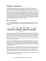
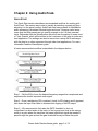
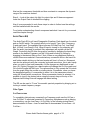
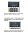
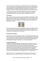
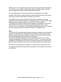
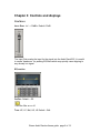
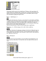
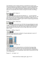
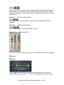
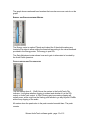
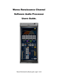
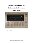
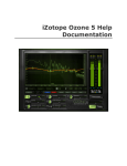
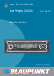
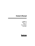
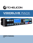
Waves AudioTrack
Software Audio Processor
Users Guide.
Waves AudioTrack software guide page 1 of 12
Chapter 1: Introduction.
Introducing Waves AudioTrack, a combined EQ, Gate and Compressor in a
single plug-in. AudioTrack offers high efficiency with great sound quality to
answer to the basic processing needs of any audio track whether in a multi track
music or sound track project or a single audio stream. The Audio track can serve
as a basic track insert like the EQ and compression found in the track strips of
professional mixing consoles to optimize the sound of the track as it goes into the
mix or to perform the basic EQ and dynamics for audio transmission, all within a
single interface and offering a clean audio path and high efficiency so that you
can open multiple instances and avoid the need to jump back and forth between
separate equalizer, gate and compressor plug-in.
WHAT IS AUDIOTRACK ?
The Waves AudioTrack Plug-In offers a 4 band paragraphic equalizer, a Gate
and a compressor or expander. The following diagram shows the AudioTrack
signal flow –
The 4 band paragraphic EQ offers fully parametric and graphic controls. Each
band can be 1 of 5 filter types – Bell, Hi-Pass (Low-cut), Low-Shelf, High-Shelf
and Low-Pass (Hi-cut). Each band offers +/-18dB of boost or cut with a variable
Q for bells and a 12dB per octave response for shelf or pass filters. The EQ is
handy for boosting or cutting certain frequency ranges in order to shape the tone
of the sound passing through.
The Gate in the AudioTrack plug-in has a dedicated threshold, floor, attack and
release controls to set the properties of the gain reduction applied to the audio.
This is most useful for shutting out noise or any low gain sounds that can only
add disturbance while passing the higher gain or significant track sounds that are
intended to be heard.
The compressor in the AudioTrack is a classic Peak Reference compressor that
applies automatic gain compensation so that the effect of the compression will
usually appear to be an increase of the audio loudness. The compressor is
equipped with the traditional controls being Threshold, Ratio, Attack and release.
The AudioTrack plug-in also has Input and Output gains to avoid clipping and set
the overall desired level for the track.
Waves AudioTrack software guide page 2 of 12
Chapter 2: Using AudioTrack.
QUICK START
This Quick Start section describes a recommended workflow for working with
AudioTrack. The easiest way to start is usually by selecting a preset and then
adjusting it to the actual context. AudioTrack has many presets for MultiMedia
audio processing, Broadcast, Musical styles and more. However useful some
users may feel that presets are not specific enough or don’t fit their personal
taste. Remember that the WaveSystem offers the user the option to create a set
of “User Presets” which will be shown in the Load menu of the plug-in under any
host application. The settings can also be saves into a setup file for exchange
with the plug-in on other computers through other host applications. For more
information read the WaveSystem guide.
A basic recommended workflow is described in the diagram below –
Step 1 – Set the EQ to focus the desired frequency ranges that complement and
emphasize the track’s important audio signal.
Step 2 - Once a satisfactory EQ is reached, check for EQ clipping and if apparent
take down the Input Gain fader to eliminate this clipping of the EQ output.
Step 3 – We recommend to first raise the GATE threshold to shut out
insignificant low level audio in the track, to find a good point look at the energy
meter in a point where the track has the lowest significant signal that needs to
pass through the gate and set the gate threshold arrow just below that point.
Waves AudioTrack software guide page 3 of 12
Next set the compressor threshold and time constants to compress the dynamic
range of the sound as desired.
Step 4 – Look at the output clip light for output clips and if these are apparent
lower the Output Gain to eliminate the clipping.
Now it is recommended to redo these steps in order to further tune the settings
until feel satisfied with the results.
For a better understanding of each component and what it can do for your sound
read this chapter through.
AUDIOTRACK EQ
The AudioTrack EQ is a 4 band Paragraphic Equalizer. Each band has 4 controls
and an On/Off switch. The controls allow you to specify Type, Gain, Frequency,
Q and each band. The available filters types are Hi-Pass(Low-Cut), Low-Shelf,
Bell, Hi-Shelf, Low-Pass(Hi-Cut). When a band is turned on it’s properties will
filter the audio Input and its spectral Gain adjustment will register on the EQ
Graph. Controlling the EQ from the graph is possible by dragging the band drag
marker to the desired Frequency on the X-Axis and boosting or cutting by
dragging to the desired Gain on the Y-Axis. When an on graph band marker is
clicked it becomes selected. Once selected any movement will turn the band On
and further double clicking on the band marker will turn it off and on. Movement
can also be achieved using the computer keyboard arrow keys, this is also handy
when you wish to fine tune parameters. All the changes are auditioned in real
time. Alt. (Option) Dragging on a band marker will change the Q of the graph and
Ctrl click will toggle the filter type. The options allow to fully operate the 4 controls
from the graph using the mouse or pointing device. Sometimes, when you know
the designated setting, it’s convenient to enter it in to the parameters control
using the WaveSystem conventions. When a parameter control is selected, it is
possible to type in the desired value using the numeric keys at the top of the
keyboard and hitting Enter will engage the dialed setting.
The EQ can be used to “Focus” the sound’s spectral properties by bringing out or
tucking in certain frequency ranges.
Filter Types
CUT/PASS FILTERS
To completely eliminate any unwanted Low Frequency audio use the Hi-Pass =
Low-Cut filter. To eliminate unwanted Hi Frequency disturbance such as hissing
or screeching, use the Low-Pass = Hi-Cut filter. In the following picture Band1
demonstrates a Hi-Pass = Low-Cut and Band 4 demonstrates a Low-Pass = HiCut filter –
Waves AudioTrack software guide page 4 of 12
The Pass/Cut filter type has a roll-off response of -12dB per Octave. The cutoff
frequency represents the point where the roll off is at -3dB. Band 1 only has the
choice for Hi-Pass and band 4 only has the choice for Low-Pass.
SHELF FILTERS
The Shelf filter as the Pass/Cut filter can boost or cut above or below a specified
frequency, but rather then rolling off to infinity the shelf will roll off or up to the
designated gain indicated in the shelf. The shelf filter’s cutoff frequency is located
in the middle of the slope so if the specified frequency is 1000Hz and the gain
+12dB then the gain at 1000Hz will be at about +6dB as demonstrated in the
following picture –
BELL FILTERS
Bell filters boost or cut a certain frequency range. The indicated frequency is the
peak of the bell filter so it is the frequency which will get the most boost or cut of
the filter. Bell filters can be wider or narrower according to the defined Q value.
Waves AudioTrack software guide page 5 of 12
The Q control does not affect Pass/Cut or Shelf filter types. For Bells however
the Q is a way to define the frequency width of the boosting or cutting bell filter. It
may be represented by the mathematical relationship: Fc/Fw (center frequency
divided by frequency width at the traditional ‘-3dB point’, both in Hertz). For
example, a Q of 2.0 at 1,000Hz gives a bandwidth of 500Hz (1000Hz divided by
2). The low Q values offer the widest bells which are great for enhancing a
complete range similar to Hi Fi Tone controls. The high Q values offer the
narrowest filters useful for eliminating a specific problematic resonance.
EQ Clipping
When you have a fairly hot signal coming into the AudioTrack and there is further
EQ introduced, there is a chance of clipping the EQ output. The AudioTrack Clip
indicator above the output meters will show whether your audio is clipped and at
what stage. In the event the clipping is introduced by EQ the Clip indicator will
Indicate clip as follows –
In this case use the Input gain to avoid clipping and crate some headroom for the
EQ. In native 32bit float processing the EQ clip will probably not appear as the
floating point allows to go well over 0dBfs before actual signal clipping occurs so
in this case most clipping will be at the output.
AUDIOTRACK DYNAMICS
AudioTrack offers 2 useful dynamics processors. A Compressor/Expander and a
Gate. The AudioTrack Dynamics section has to meter bars that provide important
visual feedback. The energy meter allows setting the thresholds according to the
program energy and the Gain adjustment meter shows the gain attenuation or
boost applied to the signal in real-time as it is dynamically applied.
Compressor/Expander
AudioTrack Compressor/Expander offers the traditional Compressor controls –
Threshold, Ratio, Attack & Release. Using these controls the user can define a
set of conditions by which the track’s gain will be adjusted dynamically.
The Threshold sets the energy reference so that as long as the audio energy is
significantly lower then the threshold, no gain adjustment will be introduced.
When the energy approaches the threshold the track gain will be adjusted
according to the ratio specified. The Attack and release time constants determine
how quickly the gain adjustment will be applied. This is set in Milliseconds.
When the ratio is 1:1 no gain adjustment will take place and this is just like
having the compressor turned off. When we increase the ratio, for example
Waves AudioTrack software guide page 6 of 12
setting a ratio of 2:1 will mean that when the input energy exceeds the threshold
by a certain amount of dB’s it will be attenuated or reduced in gain so that the
output energy will exceed the threshold by half that amount.
The gain adjustment will reach its peak by the time specified in the attack
constant. And when the energy falls below threshold the attenuation will release
according to the time specified in the release control value.
The Release time constant is helpful in setting the smoothness of the gain
adjustments so that fast release times will sound grainier or distorted while longer
release times will sound smoother or “pumping” in extreme settings.
The attack time is helpful in defining the compression’s application. Short attack
times will allow better peak control while longer attacks will create a more
“Punchy” sound. Long values for both Attack and Release can work as a leveling
process keeping the overall loudness bounded to the threshold area.
Gate
The AudioTrack Gate will simply attenuate the signal by whenever its energy falls
beneath the gate threshold. The gate will close within the time specified in the
release control and open according to the Attack time defined. The floor defines
the maximal attenuation gain introduced to the signal.
When the energy drops beneath the threshold the gate will close, or in other
words gain attenuation will begin until it reaches the floor. This will take the time
specified in the Release control. When the energy rises above the threshold the
gate will open or attenuation will stop by the time specified in the Attack control.
The attack time should be fast enough not to create a fade in effect every time
the energy rises above the threshold but sometimes a too fast attack can result in
a click sound.
Waves AudioTrack software guide page 7 of 12
Chapter 3: Controls and displays
CONTROLS
INPUT GAIN: -Inf. – 0.0dBfs. Default 0.0dB
The Input Gain scales the input for the signal into the AudioTrack EQ. It is useful
to create “headroom” for peaking EQ filters which may quickly cause clipping to
any already hot signal.
EQ section
ON/OFF: Default – Off.
Turns the filter on or off.
TYPE: HP, LP, Bell, HS, LS Default – Bell.
Waves AudioTrack software guide page 8 of 12
Determines the filter type for the related band. Clicking on the type display will
toggle between the available types for each band. Clicking on the little arrow will
display a pop-up menu with the available types to immediately select the type
you need without toggling through the rest.
GAIN: +/- 18dB Default – 0.
This control sets the mount of boost or cut introduced to a band bell or shelf filter.
For Bells the gain will correspond with the frequency, so that a bell at 1kHz with a
+6 dB boost means that 1kHz is boosted by 6dB. In shelf filters the gain will
define the overall boost and the gain at the shelf’s cutoff frequency is about half
as the cutoff is in the middle of the shelf slope.
When the selected type is Pass/Cut filter the gain has no significance.
FREQUENCY: 16 – 21357Hz Default 1-63, 2-250, 3-933, 4-4000 Hz.
This control determines the frequency reference for the band. When the type is a
bell the frequency is the middle of the bell. When the type is shelf the frequency
is the middle of the shelf slope. When the type is Pass/Cut filter, the frequency is
the -3dB point of the roll off.
Q:0.5 - 30 Default 6.
In AudioTrack Q is set for bell filters only and it defines their bandwidth or how
wide or narrow a filter will be. The lower the value, the wider the filter and vice
versa.
Comp/Expander section.
THRESHOLD: -55.0 – 0.0dBfs. Default 0.0
Waves AudioTrack software guide page 9 of 12
The threshold is a point of energy reference, so that when the energy is way
below the threshold no compression is introduced, but as the energy approaches
or passes the threshold gain adjustment will begin according the values in the
other controls. The compressor threshold is indicated with a yellow triangle and
also has a corresponding Yellow marker running at the left side of the Energy
meter.
RATIO: 0.5/1 – 40:00/1. Default 1:1
The ratio defines how the gain should be adjusted. 0.5 – 1 are the expansion
ratios and 1-40 are the compression ratios. For example, setting a ratio of 2:1 will
mean that when the input energy exceeds the threshold by a certain amount of
dB’s it will be attenuated or reduced in gain so that the output energy will exceed
the threshold by half that amount.
ATTACK: 0.1 – 1000ms. Default 2ms
The Attack time determines how long it will take for the gain adjustment to reach
it target. For example when the energy goes over threshold by 4dB and the ratio
is 2:1 the gain attenuation will take 2ms to lower the gain by 2dB. Setting short
attack times provides better peak control but longer attack times can provide
better “Punch”.
RELEASE: 1 -10000ms. Default 50.
The release value set the time it will take for the gain adjustment to reset to 0
when the energy falls below threshold.
Gate section
THRESHOLD: 0.0 - -Inf. Default –Inf.
The threshold is a point of energy reference, so that when the energy drops
beneath the threshold the gate will close or the track gain will be attenuated
according the values in the other controls. The Gate threshold is indicated with a
blue triangle and also has a corresponding Yellow marker running at the left side
of the Energy meter.
FLOOR: 0.0 - -Inf. Default –Inf.
Waves AudioTrack software guide page 10 of 12
The floor defines the maximal amount of gain attenuation that the gate will apply
when closing. You can define a floor so that the gate closes by down to 60dB
rather then shutting out to total digital silence which may produce clicks or sound
less natural.
ATTACK: 0.1 – 1000ms. Default 2.00ms
Determines the time the gate takes to open when the energy goes over the
threshold.
RELEASE: 1 – 10000ms. Default 30ms.
Release sets the time it takes for the gate to close.
OUTPUT: -24 - +12dB. Default 0dB.
This control sets the overall output gain. It can be used to prevent output clipping.
DISPLAYS
EQ GRAPH –
The EQ graph shows the total EQ gain curve designed from the 4 bands. It
shows 18dB at the Y axis and 16 – 16000 Hz in a logarithmic frequency scale.
Waves AudioTrack software guide page 11 of 12
The graph shows numbered band markers that can also serve as controls on the
graph.
ENERGY AND GAIN ADJUSTMENT METERS
The Energy meter is marked Thresh and indeed the 2 threshold markers are
located at its sides to allow setting the threshold according to the visual feedback
provided in the Energy meter. The energy is post EQ.
The Gain Adjustment meter shows how much gain is attenuated or boosted by
the AudioTrack dynamics.
OUTPUT METERS AND CLIP INDICATOR
The out meters show 0 - -30dB. Above the meters is the AudioTrack Clip
indicator. It will show whether clipping is evident and whether it’s at the EQ
output or AudioTrack output. In 32bit Floating point processing clipping will
usually occur at the output as the floating point allows to go way beyond 0.0dBfs
without any clipping of the audio.
All meters show the peak value in the peak counter beneath them. The peak
counter
Waves AudioTrack software guide page 12 of 12