1
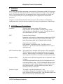
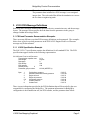
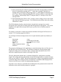
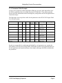
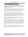
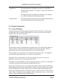
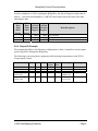
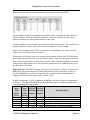
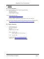
J1939 Data Mapping Explained
Revision 1.04
September 17, 2010
Pyramid Solutions, Inc
30150 Telegraph Road
Suite 200
Bingham Farms, MI 48025
Phone: 248-549-1200
FAX: 248-549-1400
www.pyramidsolutions.com
BridgeWay Product Documentation
TABLE OF CONTENTS
1. OVERVIEW .............................................................................................................1 2. J1939 MESSAGE TERMINOLOGY .....................................................................1 3. J1939 PGN MESSAGE DEFINITIONS ................................................................2 3.1 PGN AND PARAMETER DOCUMENTATION EXAMPLES .............................................2 3.1.1 J1939 Specification Example ...........................................................................2 3.1.2 Parameter Table Example ...............................................................................4 4. 4.1 4.2 4.3 5. DETERMINING THE BRIDGEWAY DATA TABLE LAYOUT .....................5 DATA TABLE LAYOUT FOR MODBUS RTU AND MODBUS TCP (BIG ENDIAN) ........5 DATA TABLE LAYOUT FOR ETHERNET/IP (LITTLE ENDIAN) ...................................6 DATA TABLE LAYOUT FOR PROFIBUS DP ............................................................6 CONFIGURING THE BRIDGEWAY I/O MAPPING .......................................7 5.1 CONFIGURATION ATTRIBUTES .................................................................................7 5.2 EXAMPLE CONFIGURATION .....................................................................................8 5.2.1 Input I/O Example ............................................................................................8 5.2.2 Output I/O Example .........................................................................................9 6. 6.1 6.2 SUPPORT ...............................................................................................................11 PRODUCT ASSISTANCE ..........................................................................................11 CONTACT INFORMATION .......................................................................................11 J1939 Data Mapping Explained
Table of Contents i
BridgeWay Product Documentation
1. Overview
When setting up an engine monitoring system the task of determining which J1939 messages
to use and where the engine parameters are located within these messages can be confusing
at best. This document provides an explanation of how engine parameters are placed into
J1939 messages and how to set up the BridgeWay I/O configuration to monitor these
parameters.
Using the recommendations detailed in this document will streamline your BridgeWay
configuration time as well as the time required to develop your application or controls logic.
2. J1939 Message Terminology
Parameter
A specific data element within a PGN message.
Each parameter has a description, resolution, range, scaling,
offset and data size defined by the vendor. Standard parameters
are defined in the SAE J1939-71 specification.
PGN
Parameter Group Number
Parameters are grouped by common purpose and assigned a PGN.
The PGN is used in J1939 messages to identify the group, and
hence the parameter data, that is contained in the message.
SPN
Suspect Parameter Number
Each parameter is assigned an SPN. The SPN is used in
diagnostics to specify the particular item that the service code is
associated with.
PGN Transmission Rate
The nominal rate at which the PGN message will be transmitted.
The PGN definition specifies the transmission rate of the PGN
message. Rates specified as “On Request” are only transmitted
when a request for a PGN is received from another network node.
Parameter Offset
The offset into the PGN message buffer where a parameter’s data
is located.
A PGN message contains the data for all of the parameters in its
associated parameter group. The PGN definition indicates where
each parameter’s data is located, based on offsets from the front
of the message buffer. Note that offsets may not be on byte
boundaries but may be bit based.
Parameter Length
The length of an individual parameter’s data.
A parameter’s data may be contained in a single bit to multiple
bytes within the PGN message buffer. Note that data length is not
always in bytes but may be a number of bits.
J1939 Data Mapping Explained
Page 1
BridgeWay Product Documentation
Parameter Resolution
The scale and offset of a parameter’s data.
The parameter data included in a PGN message is raw unsigned
integer data. The scale and offset define the translation to convert
the raw data to engineering units.
3. J1939 PGN Message Definitions
Each PGN has a message definition that specifies the size, transmission rate, and the message
layout. The message layout specifies how the data from the parameters in the group is
arranged within the message buffer.
3.1 PGN and Parameter Documentation Examples
There are many different ways that PGN message definitions are documented. The examples
below show typical ways that parameters in the PGN 65263 Engine Fluid Level/Pressure
message may be documented.
3.1.1 J1939 Specification Example
The SAE J1939-71 specification contains the definitions for all standard PGNs. The PGN
specifications appear similar to the following representation:
5.3.29 ENGINE FLUID LEVEL/PRESSURE
Transmission repetition rate:
Data length:
Data page:
PDU format:
PDU specific:
Default priority:
6
Parameter group number:
Byte:
1
2
3
4
5,6
7
8
0.5 s
8 bytes
0
254
239
65 263 (00FEEF16)
Fuel delivery pressure
Extended crankcase blow-by pressure
Engine oil level
Engine oil pressure
Crankcase pressure
Coolant pressure
Coolant level
5.2.5.27
5.2.5.241
5.2.5.72
5.2.5.28
5.2.5.40
5.2.5.38
5.2.5.73
There is more information provided in the PGN definition than will be needed by the user
responsible for configuring the BridgeWay. The pertinent information for BridgeWay
configuration is the transmission rate, the PGN number, and the parameter data offsets.
J1939 Data Mapping Explained
Page 2
BridgeWay Product Documentation
It is important to note the following:
1) In the specification, the offsets for parameter data in the message buffer are defined
by byte or bit numbers starting with “1”. In the above example, Fuel Delivery
Pressure data is at the front of the message (byte 1), while Engine Oil Pressure is in
the 4th byte. When configuring BridgeWay I/O, message offsets are used rather than
byte numbers, with message offset”0” being the front (i.e. first byte or bit) of the
message buffer.
2) Data transmitted in the PGN is “Raw” and may require scaling to arrive at the actual
data value the PGN data represents. The following section defines where the scaling
information is found.
The PGN definition describes where the data is located in the message; however the
description of the actual data is found in the individual parameter descriptions. The section
numbers to the right of the message buffer layout, specify where to find the parameter
definitions.
For instance, in the above example, the parameter definition for Engine Oil Pressure is in
section 5.2.5.28 and may appear as follows:
5.2.5.28 Engine Oil Pressure⎜Gage pressure of oil in engine lubrication system as provided by oil
pump.
Data Length:
Resolution:
Data Range:
Type:
Suspect Parameter Number:
Reference:
1 byte
4 kPa/bit gain, 0 kPa offset
0 to +1000 kPa (0 to 145 psi)
Measured
100
5.3.29
The parameter definition gives the application or controls developer the rest of the story on
the data that is in the PGN message. The definition contains the actual parameter data
length, the scaling used to convert the “Raw” parameter data transmitted on the J1939
network to engineering units, and the valid range of the data.
The only information detailed above, pertinent to BridgeWay configuration is the data
length. The scaling and range information is useful for the application or controls developer
who will use scaled or “cooked” data in their application or logic for programmatic purposes
or when the data will be displayed for the end customer on an HMI or other display device.
Likewise the SPN may be useful for understanding diagnostics.
Note that a cross reference is included in the definition from the parameter back to the PGN
definition section with which the parameter is grouped.
J1939 Data Mapping Explained
Page 3
BridgeWay Product Documentation
3.1.2 Parameter Table Example
In some cases equipment vendors and engine OEMs may provide a table that defines all of
the PGNs / parameters that are available over the J1939 data link. These tables generally
provide all of the information needed for BridgeWay configuration and for the application or
controls developer.
The following is an excerpt from a table for the parameters in the PGN 65263 Engine Fluid
Level/Pressure group.
Parameter
PGN
SPN
Offset
7 bytes
Data
Length
1 byte
Update
Rate
500ms
Coolant Level
65263
111
Coolant Pressure
65263
109
6 bytes
1 byte
500ms
Crankcase Pressure
65263
101
4 bytes
2 bytes
500ms
Engine Oil Level
65263
98
2 bytes
1 byte
500ms
Engine Oil Pressure
65263
100
3 bytes
1 byte
500ms
Extended Crankcase
blow-by Pressure
Fuel Delivery
Pressure
65263
22
1 byte
1 byte
500ms
65263
94
0 bytes
1 byte
500ms
Scaling
0.4 %/bit
0 % offset
2 kPa/bit
0 kPa offset
0.0078 kPa/bit
-250 kPa offset
0.4 %/bit
0 % offset
4 kPa/bit
0 kPa offset
0.05 kPa/bit
0 kPa offset
4 kPa/bit
0 kPa offset
Range
0-100 %
0-500 kPa
-250-251.99 kPa
1-100 %
0-1000 kPa
0-12.5 kPa
0-1000 kPa
For the user responsible for configuring the BridgeWay, each parameter row contains the
PGN number, offset into the message buffer, data length, and the expected transmission rate.
For the application and controls developer, the scaling, valid range and SPN are defined for
the parameters.
J1939 Data Mapping Explained
Page 4
BridgeWay Product Documentation
4. Determining the BridgeWay Data Table Layout
An important task when setting up the BridgeWay is determining how parameter data is
going to be placed in the module’s data table. Although BWConfig will allow you to start
adding parameters to the BridgeWay I/O tables and let the data end up where it falls, it is
suggested that more thought be put into this process, to make the application or controls
development more straight-forward.
Generally, placing parameters on word (16-bit) boundaries in the data table is suggested;
however, this is somewhat controller dependent (i.e. some controllers are “little endian” and
others are “big endian” regarding how memory values are accessed and stored). The
following sections discuss suggested data table layouts for each type of controller.
Note that J1939 PGN parameter data is stored in little endian format.
4.1 Data Table Layout for Modbus RTU and Modbus TCP (Big Endian)
It is suggested that parameters be mapped on 16-bit word boundaries in the BridgeWay for
applications with Modbus (big endian) controllers. This will result in individual parameters
being conveniently mapped to individual Modbus (16 bit) registers, which will be very useful
and efficient for the application and controls developers.
The Swap I/O Bytes option (checkbox) should be set (checked) in the BridgeWay
configuration using BWConfig. This will ensure that data in the registers is in the proper
orientation to be read by the Modbus controller.
Caveat: Parameter data with a length larger than 16 bits will span multiple Modbus registers.
Although the data in each register will be oriented correctly using this approach, the order of
the data in the spanned registers will need to be manipulated in the controller. The least
significant word will appear first in the register table. Hence a 4 byte (2 word) value will
have the low word in the first register and the high word in the second register of the data
table. This is reversed from what a Modbus controller expects and will require some
manipulation by the Modbus controller logic or code to properly orient the multiple register
data value.
Important! All data is swapped once the Byte Swapping option is checked, including
outgoing data (i.e. data coming into the BridgeWay data table from J1939 will be swapped
and data sent to the BridgeWay output table by the application or controller will be
swapped).
J1939 Data Mapping Explained
Page 5
BridgeWay Product Documentation
4.2 Data Table Layout for EtherNet/IP (Little Endian)
When determining the mapping boundaries for EtherNet/IP it must be determined how the
controller is going to use the data. ControlLogix controllers allow the connection data to be
configured as bytes, 16-bit words, or 32-bit double words. Other EtherNet/IP scanners may
treat the connection data as a simple string of bytes.
If the connection data is to be treated as bytes, parameter data can be mapped on 8-bit
boundaries. If mapped this way, any data larger than a single byte will have to be
manipulated by the controller program.
When choosing the connection data format in the controller (in the case of ControlLogix) the
size of the parameters must be taken into accout. If all parameters are 8 bits or less, then the
connection format can be configured as SINT (8-bit) data. If any of the parmeters are larger
than 8 bits, it may be beneficial to configure the connection format as INT (16-bit) or DINT
(32-bit) data. The mapping boundaries in the BridgeWay should be set according to the
selected connection configuration.
Important! Do not set the Swap I/O Bytes option for EtherNet/IP. It is not required and
should not be done.
4.3 Data Table Layout for PROFIBUS DP
It is suggested that parameters be mapped on 16-bit word boundaries for PROFIBUS (big
endian) applications. PROFIBUS requires byte swapping of multi-byte data; hence, it is best
to locate all data on 16-bit boundaries so that parameters with lengths of 8 bits or less do not
get inadvertently swapped with neighboring parameters.
The Swap I/O Bytes option should be set (checked) in the BridgeWay configuration using
BWConfig. This will ensure that the data in the registers in the right orientation to be read
by the PROFIBUS scanner.
Caveat: Parameter data with a length larger than 16 bits will span multiple words. Although
the data in each word will be oriented correctly using byte swapping, the order of the data in
the spanned words will need to be manipulated in the application or controller. The least
significant word will appear first in the data table. Hence a 4 byte (2 word) value will have
the low word first followed by the high word. This is reversed from what a PROFIBUS
controller expects and will have to be manipulated by the controller logic or program.
J1939 Data Mapping Explained
Page 6
BridgeWay Product Documentation
5. Configuring the BridgeWay I/O Mapping
Once the J1939 parameters have been identified, their details collected and the data table
layout has been determined, all that’s left is to enter all of the information into the
BridgeWay I/O configuration using BWConfig.
5.1 Configuration Attributes
Full details of the I/O configuration attributes can be found in the corresponding BridgeWay
user manual. The table below describes how the information collected above, pertains to the
BridgeWay configuration for input and output data points.
PGN
The PGN of the group associated with the parameter as specified in
the PGN definition or by the parameter table.
Priority
The priority of the message as specified in the PGN definition.
Care should be taken when assigning the Priority to an outgoing
message. If it is unclear which priority to use, consult the ECU
vendor. If it is still unclear use priority 6.
Note that the Priority is only used when configuring Output I/O
points; message priority is ignored when filtering messages for
Input I/O points.
Data Table Offset
The offset for each parameter should be set according to the desired
data table layout. e.g. If a 16-bit boundary layout is desired, the
offset should be set to an even byte boundary.
Note that the table offset will auto-increment based on the data
length of the previous parameter; you may or may not be required
to reset the value when configuring the next parameter.
Data Length
The length of the parameter data as specified in the parameter
definition.
Target Address
The address of the ECU that is producing the parameter may be
specified in the parameter table or by the vendor.
When configuring Input I/O points, in most cases the address may
be set to 255 (don’t care) so that the parameter data will be captured
regardless of its source.
When configuring Output I/O points, the address should be set as
specified by the vendor. Although it may be ok to broadcast some
data, in most cases the data which the BridgeWay will be sending
will need to be directed to a particular ECU.
J1939 Data Mapping Explained
Page 7
BridgeWay Product Documentation
Update Rate
For input parameters, the update rate must be set if the PGN’s
defined transmission rate is “on request”; otherwise the update rate
can be set to 0.
For output parameters, the update rate should be set according to
the vendor’s specification in the parameter table.
Message Offset
The offset into the message buffer for the parameter data specified
by the PGN definition or by the parameter table.
5.2 Example Configuration
5.2.1 Input I/O Example
Using the information from the parameters defined for PGN 65263 above, the following
example shows how to configure the BridgeWay to receive the Oil Pressure, Crankcase
Pressure and Fuel Pressure parameters.
The data table is using 16-bit boundaries for parameter data. Note that the table offsets are
all on even bytes. Since the Oil Pressure parameter is only 8 bits in length; a byte was
skipped in the table when setting the table offset for the second parameter.
The data lengths for each parameter were taken from the parameter table. The lengths for
Oil, Crankcase, and Fuel pressure are 1, 2, and 1 byte respectively.
Since PGN 65263 is transmitted every 500ms, the update rate was set to 0 since the
BridgeWay will not have to send a request for the PGN.
Note that it is recommended that you do not request the PGN (i.e. set the rate to other than 0)
if the PGN is already being automatically transmitted by the ECU.
The message offsets have been set according to the parameter offsets in the PGN definition.
BWConfig represents offsets in “bits (bytes,bits)” format. Therefore, Oil Pressure is in byte
4 of the message buffer or offset 24 bits (3 bytes, 0 bits) from the beginning of the buffer
using 0 as the starting data offset. Crankcase Pressure is in bytes 5 and 6, or offset 32 bits (4
bytes, 0 bits). Fuel pressure is at the beginning of the message buffer, byte 1 or offset 0 bits
(0 bytes, 0 bits) as indicated in the table shown above.
J1939 Data Mapping Explained
Page 8
BridgeWay Product Documentation
From the standpoint of a PLC scanning the BridgeWay, the data will appear in input table as
follows. Note that some BridgeWay’s (AB7645) insert status data at the front of the table
offsetting the data.
AB7645 AB7614
Data
Data
AB7645 AB7606
Table
Table Modbus Modbus
Data Description
Offset
Offset Register Register
(bytes)
(bytes)
4
0
30003
30001 Oil Pressure
6
2
30004
30002 Crankcase Pressure
8
4
30005
30003 Fuel Pressure
5.2.2 Output I/O Example
The example that follows will illustrate a configuration to allow a controller to set the engine
speed using PGN 0 through the BridgeWay.
The following is an excerpt from a parameters table showing the parameters in the PGN 0,
Torque/Speed Control.
Parameter
Control Mode
Control Condition
Control Priority
Requested Speed /
Speed Limit
Requested Torque /
Torque Limit
PGN
SPN
Offset
0
0
0
0
695
696
897
898
0
518
J1939 Data Mapping Explained
0 bits
2 bits
4 bits
1 byte
Data
Length
2 bits
2 bits
2 bits
2 bytes
Update
Rate
10ms
10ms
10ms
10ms
3 bytes
1 byte
10ms
Scaling
0.125 RPM/bit
0 RPM offset
1 %/bit
-125 % offset
Range
0 – 8031 RPM
-125 – 125 %
Page 9
BridgeWay Product Documentation
The configuration will allow control of the engine speed through the BridgeWay; hence the
Requested Speed and the control bit parameters are mapped to the output table.
The data table is using 16-bit boundaries for parameter data. Note that the table offsets are
all on even bytes. Even the control bit parameters, which are all 2 bits each, have been
placed so that they are each separated into their own words.
The data lengths for each parameter were taken from the parameter table. The length for the
Requested speed is 2 bytes, while each control bit parameter is 2 bits in length.
Based on the parameter table, PGN 0 is expected to be transmitted every 10ms; hence the
update rate is set to 10ms in the I/O entries.
The message offsets have been set according to the parameter offsets in the PGN definition.
BWConfig represents offsets in “bits (bytes,bits)” format. Therefore, Requested Speed is in
byte 2 of the message buffer or offset 8 bits (1 bytes, 0 bits) from the beginning of the buffer
using 0 as the starting data offset. The control bit parameters are all within the first byte of
the message at 2 bit offsets.
Important Note: The PGN 0 message, like most J1939 messages, is 8 bytes. However, the
BridgeWay only knows about the I/O data points that have been configured. In order to
force the BridgeWay to produce an 8 byte message, a pad bit must be configured that is
mapped to the end of the message (bit 63, or byte 7, bit 7).
From the standpoint of a PLC scanning the BridgeWay, the data will appear in output table
as follows. Note that some BridgeWays insert Run/Idle and/or Command registers at the
front of the table offsetting the data.
AB7645 AB7614
Data
Data
AB7645 AB7606
Table
Table Modbus Modbus
Data Description
Offset
Offset Register Register
(bytes)
(bytes)
4
4
41029
40001 Requested Speed
6
6
41030
40002 Speed Control Mode
8
8
41031
40003 Speed Control Condition
10
10
41032
40004 Speed Control Priority
12
12
41033
40005 Speed Control J1939 Message Padding
J1939 Data Mapping Explained
Page 10
BridgeWay Product Documentation
6. Support
6.1 Product Assistance
If you require BridgeWay product technical support by phone:
Call 248-549-1200
Dial 0 for the Operator
Ask for BridgeWay support
If you require support by email:
[email protected]
Subject: “BridgeWay Support Request”
Provide a detailed explanation of your question or issue in the email text.
You can also obtain BridgeWay related files and information online at the following URL:
http://support.pyramidsolutions.com/support-nc-bridgeway-projects.html
6.2 Contact Information
Pyramid Solutions, Inc.
30150 Telegraph Road
Suite 200
Bingham Farms, MI 48025
Phone: 1-248-549-1200
1-888-PYRASOL (797-2765) Toll Free
FAX: 1-248-549-1400
Corporate web: http://www.pyramidsolutions.com
Support web: http://support.pyramidsolutions.com
J1939 Data Mapping Explained
Page 11