1
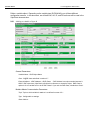
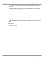
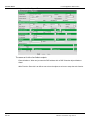
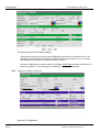
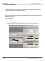
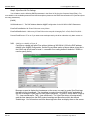
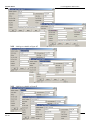
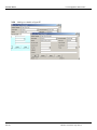
VijeoCitect and W@DE RTU DNP3 Solution Schneider Electric VJC and W@DE RTU DNP3 Solution Contents 1 VijeoCitect / W@DE DNP Solution ........................................................4 1.1 Introduction................................................................................................................ 4 1.2 Solution Architecture Diagram................................................................................ 5 2 W@DE Configuration ..............................................................................6 2.1 Web browser .............................................................................................................. 6 2.2 Settings|Operation Mode Menu ............................................................................. 6 2.3 Settings|Protocol (+TCP/IP (1)) Menu................................................................ 6 2.4 Settings|Operation Mode Menu ............................................................................. 7 2.5 Settings|Modbus Master Communication Menu ................................................. 8 2.6 Settings|Slaves Configuration Menu ...................................................................... 8 2.7 Settings|Classes Configuration Menu .................................................................... 9 2.8 Settings|Variable Configuration Menu ................................................................ 10 3 VijeoCitect Configuration..................................................................... 14 3.1 Introduction.............................................................................................................. 14 3.2 Communication Configuration.............................................................................. 14 3.3 Graphics Page Configuration................................................................................. 21 4 Alarm Demonstration ........................................................................... 22 5 Trend Demonstration............................................................................ 23 Rev: 8.0 Effective: 11-Dec-2009 Page 3 of 23 Schneider Electric VJC and W@DE RTU DNP3 Solution 1 VijeoCitect / W@DE DNP Solution 1.1 Introduction The purpose of this document is to give you a basic understanding of how to configure VijeoCitect and W@DE RTU(s) to communicate with one another via DNP3 over ethernet. There are many parameters (hundreds) available on both the VijeoCitect and the W@DE RTU side which allow you to adjust how the system functions. We will go over a few of them but it is best to consult the documentation for VijeoCitect DNP driver and the W@DE RTU configuration manuals for more details. A bit about DNP and VijeoCitect read/writing polling: DNP is a multi-layered protocol, with transactions occurring on multiple layers. This description is only concerned with protocol transactions handled directly by the VijeoCitect driver. DNP allows the master (Vijeo Citect) to poll a unit for the current value of a group of pre-configured I/O points, via a single request. This is a Class0 poll (Class 0 has all of the master’s relevant I/O points predefined), also termed as STATIC poll. Data reported as a current value is termed static data. DNP also allows the master to poll a unit for value changes in a group of pre-configured I/O points, via a single request. This is a Class1, Class2, or Class3 poll (these are all functionally equivalent, but the separate groups afford more flexibility in configuration). Data reported as a change in value (also known as an event), is termed dynamic data. An event may also include a timestamp field. DNP allows these different polls to be combined into one request. A poll for Class1, Class2 and Class3 is termed an event poll, as it will acquire all events that have been queued in the device and are awaiting transmission. A poll for Class0, Class1, Class2 and Class3 is termed an integrity poll, as it will acquire all events that have been queued in the device and are awaiting transmission, and then it will acquire a snapshot of all the current values. The VijeoCitect driver allows each unit to have its polling period, and the ratio of integrity polls to event polls, defined. The driver also supports additional functionality such that an operator can generate on demand integrity and event polls. DNP allows a unit to have the master’s address be stored internally, so that the unit(W@DE RTU) is capable of transmitting unsolicited responses of event data to the master(VijeoCitect). An event may also include a timestamp field. The VijeoCitect driver is capable of receiving and processing responses regardless of whether the response contains static or dynamic data, and regardless of whether the response is initiated by a master’s request or initiated as an unsolicited response. All responses are used to update the driver’s cache, and relevant time-stamped events are used to update configured time-stamped alarms and trends, via the DriverRuntimeInterface.dll . Write requests from VijeoCitect may result in a physical write to the device, or they may only write to cache (in the case of internal values, eg OnTime), or they may actually trigger the driver to perform a function (eg Reset Poll Counters). Read requests from Citect are serviced through the driver’s cache. Note: at the time of this document VijeoCitect DNP3 driver 4.02.12.00001 BETA was used. Rev: 8.0 Effective: 11-Dec-2009 Page 4 of 23 Schneider Electric 1.2 VJC and W@DE RTU DNP3 Solution Solution Architecture Diagram The architecture will have VijeoCitect talking DNP3 over Ethernet to a Schneider Electric W@DE RTU which in turn is talking Modbus over TCP/IP to an M340 (as the diagram below shows). Rev: 8.0 Effective: 11-Dec-2009 Page 5 of 23 Schneider Electric 2.3.2 VJC and W@DE RTU DNP3 Solution DNP3 Parmeters Configuration Port 3: SCADA Address is the DNP Address of VijeoCitect ( 3 in our case) Device Address is the DNP Address of the W@DE ( 4 in our case) We are only utilizing Port 3: 2.3.3 Application Layer This is where we actually can configure the W@DE to send unsolicited responses via a specific DNP Class. Here we are telling W@DE to only send unsolicited responses for DNP Class1 objects. We are only utilizing Port 3. 2.4 Settings|Operation Mode Menu Here is where we are telling the W@DE that we will communicate DNP3 over TCP/IP on the TCP/IP ports. Your configuration should be as follows: Rev: 8.0 Effective: 11-Dec-2009 Page 7 of 23 Schneider Electric 2.5 VJC and W@DE RTU DNP3 Solution Settings|Modbus Master Communication Menu 2.5.1 Modbus TCP Client Parameters Here we will configure the W@DE to use port 502 to communicate to the PLC. We can also setup different scan groups (Topics) on how often we want the W@DE to scan the PLC for data. In our example we will only configure Topic 1 at a 1sec scan rate. The Modbus Slave Address of the PLC is 2. When we create the variable object in the W@DE, we will assign the object to a Topic. Your configuration should be as follows: 2.6 Settings|Slaves Configuration Menu Define the IP Address of the M340 (Slave Device) and make sure it is ‘Active’. Rev: 8.0 Effective: 11-Dec-2009 Page 8 of 23 Schneider Electric 2.7 VJC and W@DE RTU DNP3 Solution Settings|Classes Configuration Menu The Class here is not the DNP Class. This is just a means to organize your data for viewing within the W@DE web environment (Monitoring Menu). Rev: 8.0 Effective: 11-Dec-2009 Page 9 of 23 Schneider Electric 2.8 VJC and W@DE RTU DNP3 Solution Settings|Variable Configuration Menu Define a variable object. Depending on the variable type (DI/DO/AI/AO) you will have different configuration screens. In this document, we will define AI, AO, DI, and DO as these will be used in the VijeoCitect demonstration. 2.8.1 Adding a variable of type AI • General Parameters: • Variable Name – DNP Object Name Class: W@DE class as defined in section 2.7 External Address: <DNP Address>, <DNP Class> - DNP Address is a unique number between 065565. DNP supervisor (VijeoCitect) will utilize this reference to access the object. DNP Class is optional. On our variable set it to be of DNP Class2. If you omit the DNP Class, it defaults to Class1. Modbus Master Communication Parameters Topic: Topic to which variable is attached - as defined in secton 2.5.1 Type: Configurable on analogs. Slave Address: Schneider Electric • • VJC and W@DE RTU DNP3 Solution Peroidic Treatment Log : Period defines how often to log into Measures Log (Diagnostics|Measures Log menu) within W@DE RTU. Event: Activate saving of event to the DNP protocol event stack according to the Type and Period criteria (create event of sample type every 10 sec). Threshold Treatment • • Dead band • • Alarm Level is the W@DE Alarm Level configured under the Settings|Alarms menu (not used in this demo) Min and Max Log • Rev: 8.0 Log and Event same as Periodic Treatment only based on deadband Alarms Configuration • • Log and Event same as Periodic Treatment only based on thresholds. Period of the logs defined. Effective: 11-Dec-2009 Page 11 of 23 Schneider Electric VJC and W@DE RTU DNP3 Solution Adding a variable of type AO The same as AI with a few fields to explain: Rev: 8.0 External Address: When we just enter the DNP address with no DNP Class the object defaults to Class1 Write Function: Since this is an AO we can write to the object so we have to setup the write function. Effective: 11-Dec-2009 Page 12 of 23 Schneider Electric 2.8.2 VJC and W@DE RTU DNP3 Solution Adding a variable of type DI The same as AI with a few fields to explain: 2.8.3 Active/Inactive Status:This is how you want it displayed on the screen in the Monitor menu. In the example here we will display words (Open or Inactive) based on the bit being on or off. It will also have a background color of red for Open and Green for Inactive. Note that for digital data any change of state on a variable automatically generates recording in the protocol event stack. For the other types of variables (AI, AO,etc) it is configurable. Adding a variable of type DO Same as DI configuration. Rev: 8.0 Effective: 11-Dec-2009 Page 13 of 23 Schneider Electric VJC and W@DE RTU DNP3 Solution 3 VijeoCitect Configuration 3.1 Introduction This manual assumes that you understand the basic concept of communication configuration within VijeoCitect including cluster configuration requirements. 3.2 Communication Configuration Step 1: In your project, launch the Communications Setup Wizard and configure a device for DNP filling out the appropriate info as required. Step 2: Manally define: Cluster: <Give it a name> Network : Use loopback (127.0.0.1) for standalone system Assign the Cluster and Network to the IOServer, Alarm, and Trend Servers configuration as shown. Rev: 8.0 Effective: 11-Dec-2009 Page 14 of 23 Schneider Electric VJC and W@DE RTU DNP3 Solution You should have the following configuration for Boards, Ports, and IODevices: Note the following: Rev: 8.0 Port configuration is where the wizard places the IP address of the W@DE (-i<no space>IP Add) and also the TCP Port as configured in the W@DE’s DNP3 IP Parameters Configuration (-P20000). IODevice is the place where the Wizard places the DNP address of the W@DE (4). -T option on the Ports form tells the driver to us TCP and not UDP (-U option). Effective: 11-Dec-2009 Page 15 of 23 Schneider Electric VJC and W@DE RTU DNP3 Solution Step 3: VijeoCitect INI File Settings You will want to set the following DNPR parameters in the Citect.ini file (thru the Computer Setup Editor). For more details on the available parameters and their descriptions please see the DNPR documentation for VijeoCitect (there are many parameters). [DNPR] SCADAAddress=3 ! The DNP Address Matches W@DE configuration for the SCADA in DNP3 Parameters EventPollPeriodDefault=30 !Event Polls occur every 30 sec EventPollRatioDefault=2 !After every 2 Event Polls on the next poll do Integrity Poll – ePoll, ePoll, iPoll,ePoll… ProcessTrendEvents=1 !Turn on if you want event trends process by the driver otherwise only alarm events on 3.2.1 Adding a variable of type AI Configure a variable tag called Flow with an Address of AI0108.Val (108 is the DNP address defined in the W@DE configuration. Set the Eng and Raw scales as shown below (since this is the LONG and we will want to trend it – remember if no scaling defined it defaults 1-32000 so need to specify limits.) Because we want to display the timestamps on the screen, we want to create VijeoCitect tags that will hold the timestamps. The timestamp is coming from the W@DE and is embedded in the DNP message to VijeoCitect on each object read/event. To get to it, we will define 2 tags (a .TS – time seconds and a .TMS – time millisecond). The VijeoCitect driver will automatically grab the time stamps from the DNP protocol message and place them within the defined variable tags. You will see how we utilize these tags later when we display them on the screen. Rev: 8.0 Effective: 11-Dec-2009 Page 16 of 23 Schneider Electric Rev: 8.0 VJC and W@DE RTU DNP3 Solution 3.2.2 Adding a variable of type AO 3.2.3 Adding a variable of type BI Effective: 11-Dec-2009 Page 17 of 23 Schneider Electric 3.2.4 Rev: 8.0 VJC and W@DE RTU DNP3 Solution Adding a variable of type BO Effective: 11-Dec-2009 Page 18 of 23 Schneider Electric VJC and W@DE RTU DNP3 Solution 3.2.6 Trend Configuration Configure an Event Trend (only event trends are supported for pushing data and timestamps in from the RTU). Rev: 8.0 Effective: 11-Dec-2009 Page 20 of 23 Schneider Electric VJC and W@DE RTU DNP3 Solution 3.3 Graphics Page Configuration The easiest thing to do is utilize the WADE_Demo project created for distribution with this document. If you don’t have a copy of the project you can create a display with the following examples For an AI (and BI) tag type such as Flow (ReadOnly): For an AO tag type such as Pump_Start_Setpoint: For an BO tag type such as Pump_Start_CMD: Rev: 8.0 Effective: 11-Dec-2009 Page 21 of 23 Schneider Electric VJC and W@DE RTU DNP3 Solution 5 Trend Demonstration Step 1: Go into runtime and confirm comms Step 2: Go to Process Analyst and add a Trend Pen. Step 3: Right mouse click and right mouse click. Go to Properties. On the Main Page tab under Process Analyst View|Pane1 select <your trend name>. On the Appearance Tab to the right select Interpolation: Stepped. Step 4: Open the W@DE Diagnostic Measures Log side by side with Process Analyst. You should see the trend values match. Step 5: Disconnect the Ethernet cable from the SCADA PC (to simulate a lost of communication) and wait a specified time period. Observe the display that was built in Section 3.3 and notice the data has gone to #COM indicating the lost of real time data. On the W@DE web interface go to the W@DE Measures log and observe samples being logged (remember in the W@DE config we said log every 10 sec). The W@DE will have put an event on the Protocol Event Stack every 10 sec as we have configured. Step 6: Observe 4-5 samples enter the log and then reconnect the VijeoCitect network connection. Upon reconnection of comms between VijeoCitect and the W@DE, VijeoCitect will go and read from the Protocol Event Stack (which contains the events in the W@DE) bringing in the ‘missed’ trend data and inserting it into the SCADA trend system. Next go to the Process Analyst, and when VijeoCitect finishes obtaining all the event data you will see the trend data fill in appropriately (this may take a minute to process the events). Check the data with that which is logged in the Measures Log (as shown above). This proves that VijeoCitect has gone out to the W@DE, pulled the Events off the Protocol Event Stack, and insert the data into the SCADA trend system. All this is done automatically by the VijeoCitect driver. Rev: 8.0 Effective: 11-Dec-2009 Page 23 of 23