1
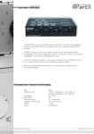
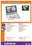
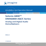
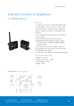
DAR-01 Rev. D User’s Manual Release Date 07/16/2015 Table Of Contents Table of Contents Introduction ........................................................................................................................................ 1 Disclaimer.............................................................................................................................................................................. 1 Warranty................................................................................................................................................................................ 1 Use and Care ....................................................................................................................................................................... 1 Contact Information ........................................................................................................................................................... 1 Overview ............................................................................................................................................. 2 Device Layout ...................................................................................................................................... 3 Front Panel ............................................................................................................................................................................ 3 Left Panel .............................................................................................................................................................................. 4 Right Panel ............................................................................................................................................................................ 5 Wiring Examples .................................................................................................................................. 6 Power..................................................................................................................................................................................... 6 Speakers-stereo ................................................................................................................................................................... 7 Speakers-mono .................................................................................................................................................................... 7 Inputs with negative common .......................................................................................................................................... 8 Inputs with positive common ............................................................................................................................................. 8 Outputs with negative common ....................................................................................................................................... 9 Outputs with positive common ......................................................................................................................................... 9 Serial to PC.......................................................................................................................................................................... 10 Serial to Other Marilyn Systems Equipment ................................................................................................................... 10 File Names ........................................................................................................................................ 11 Configuration File ............................................................................................................................... 12 INI file overview .................................................................................................................................................................. 12 [StartUp] Section ................................................................................................................................................................ 13 [Audio] Section .................................................................................................................................................................. 14 [Serial] Section.................................................................................................................................................................... 15 [Input] Section .................................................................................................................................................................... 16 [InputxMake] Section ........................................................................................................................................................ 17 [InputxBreak] Section ........................................................................................................................................................ 18 [ButtonMake] Section ....................................................................................................................................................... 19 [ButtonPress] Section ......................................................................................................................................................... 20 [ButtonBreak] Section ....................................................................................................................................................... 21 [ButtonRelease] Section ................................................................................................................................................... 22 [UserPot] Section................................................................................................................................................................ 23 [VolumeControl] Section .................................................................................................................................................. 23 [UserLed] Section ............................................................................................................................................................... 24 [PlayLed] Section ............................................................................................................................................................... 24 [StatusOutput] Section...................................................................................................................................................... 24 ButtonxMake, ButtonxBreak, VolumeControl, PlayLed, and StatusOutput Examples .................................. 25 Configuration File Application Examples ............................................................................................... 26 CONFIG.001 ........................................................................................................................................................................ 26 CONFIG.002 ........................................................................................................................................................................ 27 CONFIG.003 ........................................................................................................................................................................ 28 CONFIG.004 ........................................................................................................................................................................ 29 ASCII Serial Protocol .......................................................................................................................... 30 Firmware Upgrade ............................................................................................................................. 31 Techical Specification ......................................................................................................................... 32 Mechanical Drawings .......................................................................................................................... 33 2015, Marilyn Systems, llc. 1 Introduction Thank you for purchasing the DAR-01 digital audio repeater. This rugged, versatile, player should provide years of reliable service. The following user manual will provide the information needed to install and use this device. Disclaimer Marilyn Systems equipment is neither designed nor intended for use in safety critical applications where the potential for personal injury or property damage is present. The customer assumes full responsibility and liability for any consequences arising from such use. Marilyn Systems, llc. makes no assertion that this product is suitable for any specific application and will not be held responsible or liable in any way for improper use. Marilyn Systems strives to ensure the accuracy of the information provided in this manual. Should you find an error, please bring it to our attention so that we may correct it in a future revision. Warranty Unless stated otherwise, all products manufactured by Marilyn Systems are warranted to be free from defects in material and workmanship for a period of one year from date of purchase. Products that fail during the warranty period will be repaired or replaced at the discretion of Marilyn Systems. The warranty does not cover return shipping charges to Marilyn Systems or physical product damage due to improper configuration or application, abuse, accidents, or shipping damage. Marilyn Systems will however cover reasonable return shipping charges for products repaired or replaced under the conditions of this warranty. All products manufactured by others and sold as such by Marilyn Systems shall be governed by the terms of said manufacturer’s warranty. Use and Care The DAR-01 should be mounted securely a clean, dry environment with an operating temperature range of 0 to 38C (32 to 100F). Always operate the DAR-01 within specified parameters. Clean with a soft, damp cloth. Customer Support You may contact Marilyn Systems for technical or service support by phone or email: Phone: 210.200.8451 between the hours of 9am-6pm Central Standard Time Fax: 210.200.8487 Email: [email protected] www.marilynsystems.com Marilyn Systems, llc. 12915 Agency San Antonio, Texas 78247 2 2015, Marilyn Systems, llc. Device Overview The DAR-01 is a solid-state device that plays MP3 and WAV audio files. It can directly drive loudspeakers with a powerful, built-in amplifier, or, it can be interfaced to an external audio system using the line-level outputs. Up to 500 audio tracks are stored on an SD or SDHC flash memory card and called up using the eight optically-isolated inputs, the serial port, or internally. A simple, plain-English configuration file allows the user the flexibility to modify all operating parameters to suit their needs. Being a standard text file, the user needs only a text editor on the platform of their choice to quickly make configuration changes - no specialized software is required. A convenient user interface consisting of various status LEDs, a test button, and a volume control potentiometer are present on the front of the unit. A solid-state relay output provides devices status. Out of the box, the DAR-01 can be surface or edge mounted. An optional DIN-rail mount kit is available for standardized integration into industrial panels. A card-guard kit is also available to prevent card removal. Updating the firmware on the DAR-01 is a snap and ensures that you always have the newest features. The latest firmware is always available on our website at www.marilynsystems.com. The Revision D DAR-01 is differentiated from its predecessors by: A more powerful, 80-Watt amplifier An RS-232 serial interface replaces the RS-485 port found on previous models. This version had a single RJ-45 jack as opposed to two. The volume control now has a knob rather than being recessed Unique silkscreen graphics. 2015, Marilyn Systems, llc. 3 Unit Layout Figure 1 – Front View ACTivity Indicator The yellow ACT indicator shows both the current state of the player and any occurring activity. Indication Slow blink Fast blink short flash every second ½-second flash Table 1 Function No flash card inserted or no usable configuration file/media found on the card DAR-01 is reading the configuration file and analyzing any media present on the flash card Unit is operating normally Indicates input or serial activity ERRor Indicator The red ERR indicator lights when an issue is present. MEMORY CARD slot All sound files and configuration information are stored a SD or SDHC flash memory card. The card is inserted by gently pushing it into the socket, with the contacts down and towards the DAR-01, until a “click” is heard. To remove the card, push it in slightly until a “click” is heard. The card is now unlocked and will be ejected from the socket. If you wish to prevent removal of the card, an optional guard cover is available. TEST button This momentary pushbutton switch provides a user-programmable means of testing the unit. Please refer to the configuration section for more details. PLAY LED The red PLAY indicator lights to indicate that the unit is playing audio VOLume Potentiometer This programmable potentiometer provides control over upper and lower limits or can be disabled. Please refer to the configuration section for more details. 4 2015, Marilyn Systems, llc. Figure 2 – Left View INputs Connector Eight non-polarized, optically-isolated inputs are available for triggering tracks and performing other actions. The entire group shares a single common. The inputs can accept 12-24VDC and draw a maximum of 10mA. Please refer to figures 7 & 8 for wiring examples. Terminal 1 2 3 4 5 6 7 8 C Function Input Input Input Input Input Input Input Input Input 1 2 3 4 5 6 7 8 Common Table 2 OUTput Connector A solid-state relay output is available for various functions. This relay can switch 100mA at 24VDC, enough to drive a typical electromechanical relay, lamp, or other similar device. Please refer to figures 9 & 10 for wiring examples. Terminal C NO Function Status output common contact Status output normally-open contact Table 3 SERIAL Connector RS-232 port brought out on an EIA-561 compatible RJ-45 jack. See configuration file section for serial port operating parameters. Terminal 1 2 3 4 5 6 7 8 Pin-out (cable-end, connector front) 2015, Marilyn Systems, llc. Function NC NC NC Signal Ground DAR-01 Rx DAR-01 Tx Reserved NC Table 4 5 Figure 3 – Right View LINE-LEVEL AUDIO Jacks Two RCA, line-level output jacks marked A (left) and B (right) are provided for connection to an external audio system. These outputs are always active regardless of the state of the amplifier. AMPLIFIER OUT Connector A 40W-per-channel, stereo amplifier which can directly drive a 4 to 8-ohm loudspeaker load (see figure 5). Optionally, the outputs may be paralleled for a single, 80W output by jumping together both positive terminals and both negative terminals respectively (see figure 6 for a wiring example). PLEASE NOTE that a mono audio file must be used when the outputs are paralleled. The amplifier can be disabled if it will not be used. Please refer to the configuration information below for more details. Terminal AA+ BB+ Channel Channel Channel Channel A A B B Function (left) negative terminal (left) positive terminal (right) negative terminal (right) positive terminal Table 5 If you are upgrading from a rev. b or rev. c DAR-01, please notice that the amplifier output pin-outs have changed. 24VDC IN Connector The DAR-01 can operate on a little as 12VDC however for optimal amplifier performance, 24VDC should be provided. With the amplifier enabled, a minimum 100Watt supply should be used. Do not use an unregulated supply as this could damage the player. See figure 4 for a wiring example. Terminal + Table 6 6 Function Power supply positive Power supply ground 2015, Marilyn Systems, llc. Power Wiring Example Figure 4 – Power wiring example 2015, Marilyn Systems, llc. 7 Speaker Wiring Examples Figure 5 – Stereo speaker wiring example Figure 6 – Mono speaker wiring example (amp paralleled) 8 2015, Marilyn Systems, llc. Input Wiring Examples Figure 7 – Inputs with negative common wiring example Figure 8 – Inputs with positive common wiring example 2015, Marilyn Systems, llc. 9 Output Wiring Examples Figure 9 – Output with negative common wiring example Figure 10 – Output with positive common wiring example 10 2015, Marilyn Systems, llc. Serial Port Wiring Examples Figure 11 – DAR-01 to computer RS-232 serial port wiring Figure 12 – DAR-01 to other EIA-561 serial device wiring 2015, Marilyn Systems, llc. 11 File Names All DAR-01 files are named in the standard 8.3 format. This consists of an eight-character file name and a three-character extension separated by a ‘.’ period. All upper-case characters should be used. Example: FILENAME.EXT Is a valid 8.3 file name. Filename.Ext Is not. Audio files on the DAR-01 must be named in a very specific format so that the unit can find and access them. The first 5 characters of the filename are always ‘SOUND’ followed by a 3-digit decimal number representing the track number. This number shall be in the range of ‘001’ to ‘500’ to represent the track number. All leading zeros must be present. MP3 sound files will always have an ‘MP3’ extension and WAV files will always have a ‘WAV’ extention. It is important to keep these extensions straight as the audio will not play correctly for incorrectly named files. Numbers cannot overlap between MP3 and WAV files meaning that there cannot be SOUND001.MP3 and SOUND001.WAV on the same card. Example: 12 SOUND001.MP3 An MP3 file which will be referred to simply as “1” within the player. SOUND255.WAV Track 255 is a WAV file. 2015, Marilyn Systems, llc. Configuration File The DAR-01 configuration file specifies all operating parameters for the player. A simple text format allows for editing from any computer or operating system. This file must be named CONFIG.TXT so that the player can find it on startup. The configuration file for the DAR-01 is based on the standard INI file format. Each operating parameter of the DAR-01 consists of a name and value separated by an equal sign (=). name = value Parameters are grouped by section. The section name appears on its own line in square brackets. [section] Comments may be added and are preceded with a semicolon. Comments are for documentation purposes only and are ignored by the DAR-01. ; comment text Please note: Default values are assumed on all parameters if the parameter is not defined or defined incorrectly. 2015, Marilyn Systems, llc. 13 [Startup] section The Startup section defines the behavior of the DAR-01 immediately after power-up or card insertion. Startup section parameters: Action - Describes what the player should do when powered up. Value DoNothing Play PlayToEnd Loop BGM Function Take no action (Default) Play the specified track(s). Plays the specified track(s) uninterrupted. Loops the specified track(s). BGM mode. In BGM mode, the selected tracks are played in a sequential loop. Whenever another event is triggered, the current BGM track is paused until the end of the interrupting track at which time the BGM track resumes. Using the FadeRate allows for the BGM track to fade back in slowly. Stop is the only event that can stop BGM mode. Table 7 FirstTrack – Specifies the first track to be played by the startup action. Must be an integer in the range of 1-500. This number corresponds to the three-digit number in the file name of an audio track. LastTrack – Specifies the last track to be played by the startup action. Must be an integer in the range of 1-500. LastTrack must be greater than or equal to FirstTrack. Retentive – Track count is retained for this action when enabled. Value Yes No Function Do not retain track count (Default). Retain track count. Table 8 Volume – Volume level for this action. 0-100%. If this is not defined, the volume will not be affected. FadeRate – Defines how long the volume should take to ramp from the current level to the new level defined by this action. 10mS increments (10= 1 second). If zero, then no fade occurs. Zero is default. No fade if volume is not defined. Example: ; In this example, we will loop tracks 1 through 5 at ; full volume on startup [Startup] Action= Loop FirstTrack= 1 LastTrack= 5 Volume= 100 FadeRate= 0 14 2015, Marilyn Systems, llc. [Audio] Section Describes the audio configuration of the player. Audio section parameters: AmpEnabled - Enable or disable the built in amplifier. Value Yes No Function Amp is enabled Amp is disabled (default) Table 9 AmpBoost – When enabled (Yes), the audio signal gain is boosted to provide full power to 8-ohm speaker loads. Make sure to disable this if you are using 4-ohm speakers as the amplifiers may shut down to prevent damage. Value Yes No Function Amp gain boost is enabled – 8-ohm speakers attached Amp gain boost is disabled (default) 4-ohm speakers attached Table 10 Example: ; Enable the internal amplifier with amp boost [Audio] AmpEnabled=Yes AmpBoost=Yes ; In this example, we disable the amplifier. Note that this is not ; necessary as parameters assigned to their default values do not ; need to be specified in the configuration file. [Audio] AmpEnabled=No AmpBoost= No 2015, Marilyn Systems, llc. 15 [Serial] Section Configure the serial communication port. Serial section parameters: Mode - Defines the operating mode of the serial port Value Disabled ASCII Function The serial port is not used (default) The unit will respond to plain-text commands. No parity, 8-bit character, 1 stop bit. Baud rate is user defined. Table 11 BaudRate - Defines which baud rate to use. This parameter will be ignored if the serial port is disabled. Available baud rates are: Value 300 600 1200 2400 4800 9600 19200 31250 36400 57600 115200 250000 Function Serial port operates at 300 baud. 600 baud 1200 baud 2400 baud 4800 baud 9600 baud (default) 19.2k baud 31.25k baud 36.4k baud 57.6k baud 115.2k baud 250k baud Table 12 SerialAddress- Defines the serial communications address this device will respond to. This number must be in the range of 1 to 254 and if not defined, the DAR-01 will respond to all serial messages. This parameter will be ignored if the serial port is disabled. Note that this not currently used but left in for compatibility with previous models. Example: ; Enable the serial port for ASCII operation at 9600 Baud. ; Note that we do not specify the baud rate as we are using ; the default value. [Serial] Mode=ASCII ; Enable the serial port for ASCII operation at 57.6Kbaud. [Serial] Mode=ASCII BaudRate=57600 16 2015, Marilyn Systems, llc. [Inputs] Section Defines how the device will respond to the optically-isolated inputs. Inputs section parameters: Mode – Sets the general operating mode of the inputs. Value Individual Function The function of each input can be independently defined (default) Table 12 Eg. ; Inputs operate individually [Inputs] Mode=Individual 2015, Marilyn Systems, llc. 17 [InputxMake] Section Defines a make (on) action for the specified input x. InputxMake section parameters: Action - Describes what the player should do when the defined input is made (power is applied). Value DoNothing Play PlayToEnd Loop Pause Next Prev Stop BGM Function Take no action (Default) Play the specified track(s) Play the specified track(s) uninterrupted Loop the specified track(s) Pause the currently playing track. Play, Loop, or PlayToEnd will resume playback Advance to the next track Jump to the previous track Stop the currently playing track BGM mode. In BGM mode, the selected tracks are played in a sequential loop. Whenever another event is triggered, the current BGM track is paused until the end of the interrupting track at which time the BGM track resumes. Using the FadeRate allows for the BGM track to fade back in slowly. Stop is the only event that can stop BGM mode Table 13 EvaluateAtStartup – Evaluate input make on startup Value Yes No Function Evaluate input make on startup Ignore input on startup (default) Table 14 FirstTrack – Specifies the first track to be played by the input make action. Must be an integer in the range of 1-500. This number corresponds to the three-digit number in the file name of an audio track. If not defined, FirstTrack will default to the input number of the defined action (eg. Input4Make means that FirstTrack=4). LastTrack – Specifies the first track to be played by the input make action. Must be an integer in the range of 1-500. If not defined, this parameter will default to the value defined in FirstTrack. LastTrack must be greater than or equal to FirstTrack. Retentive – Track count is retained for this input make event action when enabled. This enables multiple “lists” to be played in order regardless of other triggered actions. Value Yes No Function Retain track count Track count will be reset to FirstTrack each time this action is interrupted by a different action (default). Table 15 Volume – Volume level for this action. 0-100%. If not defined, the volume will not be affected by this input action. Note that volume control is still active regardless of the defined action. This allows for an input to perform a duck or mute function without affecting the currently playing track. FadeRate – Defines how long the volume should take to ramp from the current level to the new level defined by this action. 10mS increments (10= 1second). If zero (default value), then no fade will occur. Fading is disabled by default if volume is undefined. Fading is still active regardless of the defined action. Maximum value is 255 (25.5 seconds). 18 2015, Marilyn Systems, llc. [InputxBreak] Section Defines a break (off) action for the specified input x. InputxBreak section parameters: Action - Describes what the player should do when the defined input breaks (power is removed). Value DoNothing Play PlayToEnd Loop Pause Next Prev Stop BGM Function Take no action (Default) Play the specified track(s) Play the specified track(s) uninterrupted Loop the specified track(s) Pause the currently playing track. Play, Loop, or PlayToEnd will resume playback Advance to the next track Jump to the previous track Stop the currently playing track BGM mode. In BGM mode, the selected tracks are played in a sequential loop. Whenever another event is triggered, the current BGM track is paused until the end of the interrupting track at which time the BGM track resumes. Using the FadeRate allows for the BGM track to fade back in slowly. Stop is the only event that can stop BGM mode Table 16 EvaluateAtStartup – Evaluate input break on startup Value Yes No Function Evaluate input break on startup Ignore input on startup (default) Table 17 FirstTrack – Specifies the first track to be played by the input break action. Must be an integer in the range of 1-500. This number corresponds to the three-digit number in the file name of an audio track. If not defined, FirstTrack will default to the input number of the defined action (eg. Input4Make means that FirstTrack=4). LastTrack – Specifies the first track to be played by the input break action. Must be an integer in the range of 1-500. If not defined, this parameter will default to the value defined in FirstTrack. LastTrack must be greater than or equal to FirstTrack. Retentive – Track count is retained for this input break action when enabled. This enables multiple “lists” to be played in order regardless of other triggered actions. Value Yes No Function Retain track count Track count will be reset to FirstTrack each time this action is interrupted by a different action Table 18 Volume – Volume level for this action. 0-100%. If not defined, the volume will not be affected by this input action. Note that volume control is still active regardless of the defined action. This allows for an input to perform a duck or mute function without affecting the currently playing track. FadeRate – Defines how long the volume should take to ramp from the current level to the new level defined by this action. 10mS increments (10= 1second). If zero (default value), then no fade will occur. Fading is disabled by default if volume is undefined. Fading is still active regardless of the defined action. Maximum value is 255 (25.5 seconds). 2015, Marilyn Systems, llc. 19 20 2015, Marilyn Systems, llc. [ButtonMake] Section Deprecated and used only for backwards compatibility. Use [ButtonPress] instead. Defines a make (pressed) action for the test button. ButtonMake section parameters: Action - Describes what the player should do when the button is pressed. Value DoNothing Play PlayToEnd Loop Pause Next Prev Stop BGM Function Take no action (Default) Play the specified track(s) Play the specified track(s) uninterrupted Loop the specified track(s) Pause the currently playing track. Play, Loop, or PlayToEnd will resume playback Advance to the next track Jump to the previous track Stop the currently playing track BGM mode. In BGM mode, the selected tracks are played in a sequential loop. Whenever another event is triggered, the current BGM track is paused until the end of the interrupting track at which time the BGM track resumes. Using the FadeRate allows for the BGM track to fade back in slowly. Stop is the only event that can stop BGM mode Table 19 FirstTrack – Specifies the first track to be played when the button is pressed. Must be an integer in the range of 1-500. This number corresponds to the three-digit number in the file name of an audio track. If not defined, FirstTrack will default to 1. LastTrack – Specifies the first track to be played by the button make action. Must be an integer in the range of 1-500. This enables multiple “lists” to be played in order regardless of other triggered actions. LastTrack must be greater than or equal to FirstTrack. Retentive – Track count is retained for the button make action when enabled. This enables multiple “lists” to be played in order regardless of other triggered actions. Value Yes No Function Retain track count Track count will be reset to FirstTrack each time this action is interrupted by a different action Table 20 Volume – Volume level for this action. 0-100%. If not defined, the volume will not be affected by a button press. Note that volume control is still active regardless of the defined action. This allows the button to perform a duck or mute function without affecting the currently playing track. FadeRate – Defines how long the volume should take to ramp from the current level to the new level defined by the button press. 10mS increments (10= 1second). If zero (default value), then no fade will occur. Fading is disabled by default if volume is undefined. Fading is still active regardless of the defined action. Maximum value is 255 (25.5 seconds). 2015, Marilyn Systems, llc. 21 [ButtonPress] Section Defines a button pressed action for the test button. ButtonPress section parameters: Action - Describes what the player should do when the button is pressed. Value DoNothing Play PlayToEnd Loop Pause Next Prev Stop BGM Function Take no action (Default) Play the specified track(s) Play the specified track(s) uninterrupted Loop the specified track(s) Pause the currently playing track. Play, Loop, or PlayToEnd will resume playback Advance to the next track Jump to the previous track Stop the currently playing track BGM mode. In BGM mode, the selected tracks are played in a sequential loop. Whenever another event is triggered, the current BGM track is paused until the end of the interrupting track at which time the BGM track resumes. Using the FadeRate allows for the BGM track to fade back in slowly. Stop is the only event that can stop BGM mode Table 21 FirstTrack – Specifies the first track to be played when the button is pressed. Must be an integer in the range of 1-500. This number corresponds to the three-digit number in the file name of an audio track. If not defined, FirstTrack will default to 1. LastTrack – Specifies the first track to be played by the button make action. Must be an integer in the range of 1-500. This enables multiple “lists” to be played in order regardless of other triggered actions. LastTrack must be greater than or equal to FirstTrack. Retentive – Track count is retained for the button make action when enabled. This enables multiple “lists” to be played in order regardless of other triggered actions. Value Yes No Function Retain track count Track count will be reset to FirstTrack each time this action is interrupted by a different action Table 22 Volume – Volume level for this action. 0-100%. If not defined, the volume will not be affected by a button press. Note that volume control is still active regardless of the defined action. This allows the button to perform a duck or mute function without affecting the currently playing track. FadeRate – Defines how long the volume should take to ramp from the current level to the new level defined by the button press. 10mS increments (10= 1second). If zero (default value), then no fade will occur. Fading is disabled by default if volume is undefined. Fading is still active regardless of the defined action. Maximum value is 255 (25.5 seconds). 22 2015, Marilyn Systems, llc. [ButtonBreak] Section Deprecated and used only for backwards compatibility. Use [ButtonRelease] instead. Defines a break (released) action for the test button. ButtonBreak section parameters: Action - Describes what the player should do when the button is released. Value DoNothing Play PlayToEnd Loop Pause Next Prev Stop BGM Function Take no action (Default) Play the specified track(s) Play the specified track(s) uninterrupted Loop the specified track(s) Pause the currently playing track. Play, Loop, or PlayToEnd will resume playback Advance to the next track Jump to the previous track Stop the currently playing track BGM mode. In BGM mode, the selected tracks are played in a sequential loop. Whenever another event is triggered, the current BGM track is paused until the end of the interrupting track at which time the BGM track resumes. Using the FadeRate allows for the BGM track to fade back in slowly. Stop is the only event that can stop BGM mode Table 23 FirstTrack – Specifies the first track to be played when the button is released. Must be an integer in the range of 1-500. This number corresponds to the three-digit number in the file name of an audio track. If not defined, FirstTrack will default to 1. LastTrack – Specifies the last track to be played when the button is released. Must be an integer in the range of 1-500. This enables multiple “lists” to be played in order regardless of other triggered actions. LastTrack must be greater than or equal to FirstTrack. Retentive – Track count is retained for the button break action when enabled. This enables multiple “lists” to be played in order regardless of other triggered actions. Value Yes No Function Retain track count Track count will be reset to FirstTrack each time this action is interrupted by a different action Table 24 Volume – Volume level for this action. 0-100%. If not defined, the volume will not be affected when the button is released. Note that volume control is still active regardless of the defined action. This allows for a button release to perform a duck or mute function without affecting the currently playing track. FadeRate – Defines how long the volume should take to ramp from the current level to the new level defined by the button release. 10mS increments (10= 1second). If zero (default value), then no fade will occur. Fading is disabled by default if volume is undefined. Fading is still active regardless of the defined action. Maximum value is 255 (25.5 seconds). 2015, Marilyn Systems, llc. 23 [ButtonRelease] Section Defines the button released action for the test button. ButtonRelease section parameters: Action - Describes what the player should do when the button is released. Value DoNothing Play PlayToEnd Loop Pause Next Prev Stop BGM Function Take no action (Default) Play the specified track(s) Play the specified track(s) uninterrupted Loop the specified track(s) Pause the currently playing track. Play, Loop, or PlayToEnd will resume playback Advance to the next track Jump to the previous track Stop the currently playing track BGM mode. In BGM mode, the selected tracks are played in a sequential loop. Whenever another event is triggered, the current BGM track is paused until the end of the interrupting track at which time the BGM track resumes. Using the FadeRate allows for the BGM track to fade back in slowly. Stop is the only event that can stop BGM mode Table 25 FirstTrack – Specifies the first track to be played when the button is released. Must be an integer in the range of 1-500. This number corresponds to the three-digit number in the file name of an audio track. If not defined, FirstTrack will default to 1. LastTrack – Specifies the last track to be played when the button is released. Must be an integer in the range of 1-500. This enables multiple “lists” to be played in order regardless of other triggered actions. LastTrack must be greater than or equal to FirstTrack. Retentive – Track count is retained for the button break action when enabled. This enables multiple “lists” to be played in order regardless of other triggered actions. Value Yes No Function Retain track count Track count will be reset to FirstTrack each time this action is interrupted by a different action Table 26 Volume – Volume level for this action. 0-100%. If not defined, the volume will not be affected when the button is released. Note that volume control is still active regardless of the defined action. This allows for a button release to perform a duck or mute function without affecting the currently playing track. FadeRate – Defines how long the volume should take to ramp from the current level to the new level defined by the button release. 10mS increments (10= 1second). If zero (default value), then no fade will occur. Fading is disabled by default if volume is undefined. Fading is still active regardless of the defined action. Maximum value is 255 (25.5 seconds). 24 2015, Marilyn Systems, llc. [UserPot] Section Deprecated and used only for backwards compatibility. Use [VolumeControl] instead. Defines the function of the front panel potentiometer UserPot Section Parameters: Mode – operating mode for the potentiometer Value Disabled Volume Function The potentiometer has no assigned function (default) The potentiometer acts as a volume control Table 27 Min - Sets the minimum value of the built in potentiometer. Defined as 0 to 100% of full scale. 0 is default. Max - Sets the maximum value of the built in potentiometer. Defined as 0 to 100% of full scale. 100 is default. [VolumeControl] Section Defines the function of the volume control potentiometer VolumeControl Section Parameters: Enabled – enable or disable the volume control Value Yes No Function The volume control is enabled (default) The volume control is disabled and the DAR-01 volume level is fixed at the defined Max level Table 28 Min - Sets the minimum volume. Defined as 0 to 100% of full scale. 0 is default. Max - Sets the maximum volume. Defined as 0 to 100% of full scale. 100 is default. 2015, Marilyn Systems, llc. 25 [UserLed] Section Deprecated and used only for backwards compatibility. Use [PlayLed] instead. Defines the function of the front panel user LED. UserLed Section Parameters: Mode - User LED operating mode. Value Disabled Playing Stopped Function The LED does nothing The LED will light while a track is playing (default) The LED will light while the unit is stopped Table 29 [PlayLed] Section Defines the function of the play LED PlayLed Section Parameters: Enabled - Enable or disable play LED Value Yes No Function The LED will light while a track is playing (default) The LED is disabled and will not light Table 30 [StatusOutput] Section Defines the function of the status output solid-state relay. Mode - Status output operating mode. Value Disabled Playing Stopped Function The status output does nothing The status output is active while a track is playing (default) The status output is active while the unit is stopped Table 31 26 2015, Marilyn Systems, llc. [ButtonMake], [ButtonBreak], [VolumeControl], [PlayLed], and [StatusOutput] Examples ;********** ; The button does nothing when pressed (made). ; specified since this is the default action. This does not have to be [ButtonMake] Action= DoNothing ;********** ; Play track 1 at full volume when button is pressed. [ButtonMake] Action= Play FirstTrack= 1 Volume= 100 ;********** ; Play tracks 12 ; will be played ; will jump back ; current volume through 25 uninterrupted when input 5 breaks. One track on each break. Once LastTrack has been played, the count to FirstTrack. Note that if volume is not specified, the level will be used. [Input5Break] Action= PlayToEnd FirstTrack= 12 LastTrack= 25 ;********** ; Stop all playback when input 1 makes. Note that this is the only action ; that can interrupt a track started with PlayToEnd. [Input2Make] Action= Stop ;********** ; Volume Control configured to control volume from 0 to 100 percent. [VolumeControl] Enabled= Yes Min= 0 Max= 100 ;********** ; Alternately we can set different end points to limit the overall ; range [VolumeControl] Enabled= Yes Min= 50 Max= 75 ;********** ; Play LED will light when the unit is playing audio [PlayLed] Enabled= Yes ;********** ; The status output relay contacts will close when audio playback is ; stopped. [StatusOutput] Mode= Stopped 2015, Marilyn Systems, llc. 27 Configuration File Application Examples Following are various examples of configuration files for common applications. These files are available for download at www.marilynsystems.com. Any of these files can be used as a template for your own application by saving a copy as CONFIG.TXT and editing as needed. File: CONFIG.001 ; Example DAR-01 Configuration File ; Written by: JLP ; -Tracks 12 through 27 will loop endlessly on startup. ; -Internal amplifier is disabled. ; -Volume control controls volume from 0 to 100 percent. ; -Play LED is lit while playing. ; -Status output contacts are closed while playing. ; ; **NOTE** The inputs and buttons do not have any assigned actions and ; therefore do not need to be specified. [Startup] Action= Loop FirstTrack= 12 LastTrack= 27 Volume= 100 [Audio] AmpEnabled= No [Serial] Mode= Disabled [VolumeControl] Enabled= Yes Min= 0 Max= 100 [PlayLed] Enabled= Yes [StatusOutput] Mode= Playing 28 2015, Marilyn Systems, llc. File: CONFIG.002 ; ; ; ; ; ; ; ; ; ; ; ; ; ; Example DAR-01 Configuration File Written by: JLP -Tracks 12 through 27 will be looped endlessly in BGM mode. each time the BGM loop is interrupted, the volume will take 2 to ramp up to the set level of 80 percent. -Play one track at a time from 1 through 5 each time input 1 is made. -Internal amplifier is enabled with boost for 8-ohm speakers. -Volume control enabled from 0 to 100 percent. -Play LED is lit while playing. -Status output contacts are closed while playing. [Startup] Action= BGM FirstTrack= 12 LastTrack= 27 Volume= 80 FadeRate= 20 [Audio] AmpEnabled= Yes AmpBoost= Yes [Input1Make] Action= Play FirstTrack= 1 LastTrack= 5 [VolumeControl] Enabled= Yes Min= 0 Max= 100 [PlayLed] Enabled= Yes [StatusOutput] Mode= Playing 2015, Marilyn Systems, llc. 29 File: CONFIG.003 ; ; ; ; ; ; ; ; ; ; ; ; ; ; ; ; ; ; ; Example DAR-01 Configuration File Written by: JLP -Tracks 12 through 27 will be looped endlessly in BGM mode. each time the BGM loop is interrupted, the volume will take 5 to ramp up to the set level of 80 percent. -Play one track at a time from 1 through 5 each time input 1 is made. Retentive is enabled which means that the track count will be maintained for this input action even if another input action occurs. -Play one track at a time from 6 through 11 each time input 2 is made. Retentive is enabled which means that the track count will be maintained for this input action even if another input action occurs. -Internal amplifier is enabled. Boost is disabled for 4-ohm speakers. -User Level pot controls volume from 0 to 100 percent. -User LED is lit while playing. -Status output contacts are closed while playing. [Startup] Action= BGM FirstTrack= 12 LastTrack= 27 Volume= 80 FadeRate= 50 [Audio] AmpEnabled= Yes AmpBoost= No [Input1Make] Action= Play FirstTrack= 1 LastTrack= 5 Retentive= Yes [Input2Make] Action= Play FirstTrack= 6 LastTrack= 11 Retentive= Yes [VolumeControl] Enabled= Yes Min= 0 Max= 100 [PlayLed] Enabled= Yes [StatusOutput] Mode= Playing 30 2015, Marilyn Systems, llc. File: CONFIG.004 ; ; ; ; ; ; ; ; Example DAR-01 Configuration File Written by: JLP -Track 1 will play each time input 1 is made. -Internal amplifier is enabled. Amp boost is disabled by default -User Level pot controls volume from 0 to 100 percent. -User LED is lit while playing. -Status output contacts are closed while playing. [Startup] Action= DoNothing [Audio] AmpEnabled= Yes [Input1Make] Action= Play FirstTrack= 1 [VolumeControl] Enabled= Yes Min= 0 Max= 100 [PlayLed] Enabled= Yes [StatusOutput] Mode= Playing 2015, Marilyn Systems, llc. 31 ASCII Serial Protocol The ASCII serial protocol is specified in the “Mode” parameter of the [Serial] section. The communication speed specified in the [BaudRate] parameter will be used. All characters are 8-bit, no-parity, 1-stop bit. ASCII serial commands consist of an optional address, a two-character command mnemonic, and an optional list of comma-separated parameters. Addresses and numeric parameters are specified as unsigned integer values. Leading zeros are not necessary and will be ignored if included. All serial commands are terminated with a “CR” (0x0D) character. Address Number from 1 to 255. If the address matches that set in the configuration file, the player will respond to the following command. An address of 255 is regarded as a broadcast address and all devices on the serial bus will respond to the following command. Commands and Parameters Mnemonic Parameter 1 Track Parameter 2 First Track Track Last Track BG First Track Last Track VL FD Volume Fade Rate Volume PL ST PA NX PR LP PE Parameter 3 Volume Parameter 4 Fade Rate Description Play specified track Stop Playback Pause playback Skip to next track Skip to previous track Loop tracks Play specified track to end (uninterrupted) BGM mode loop. Fade rate and volume will remain in effect until BGM mode is stopped Set Volume (0 to 100) Fade volume from current level to specified level at the specified rate Table 32 Examples: PL02 – Play track 2 on the DAR-01 ST – Stop the DAR-01 BG1,10,100,20 – Loop tracks 1 through 10 in BGM mode. Volume = 100 and fade-time = 2 seconds. 03PL04 – Play track 4 on the DAR-01 with address 3. 32 2015, Marilyn Systems, llc. Firmware Upgrade The firmware on the DAR-01 can be upgraded by simply inserting a memory card with the update file present. The latest firmware will always be available from our website at www.marilynsystems.com. To upgrade the firmware in your player, please use the following procedure: 1. Copy the firmware file (DAR01.MSF) to the root directory of the card. DO NOT place it in a folder as it will not be found by the bootloader. Do not rename the file or change any file attributes. 2. With the DAR-01 powered off, insert the memory card. 3. Power the DAR-01. Both LEDs will begin to flash. Be patient as the upgrade process can take up to a minute. 4. Once the update is complete, the unit will boot normally. 2015, Marilyn Systems, llc. 33 DAR-01 Technical Specification Audio Storage Controls I/O Plays MP3 files at rates up to 320Kb/s and 16-bit WAV files at up to 44.1KHz Unbalanced 2VRMS stereo line-out Class-D stereo amplifier delivers 40Watts-per-channel into a 4 to 8 ohm load at 24VDC SD or SDHC flash card Volume control potentiometer Test button Activity, Error, and Play LED 8 configurable, optically-isolated, sourcing or sinking inputs RS-232 control port User-configurable solid-state SPST output capable of driving 100mA @ 24V Power 12-24VDC @ 100W(amplifier enabled). Connectors Physical 34 Power in: 2-position, 5.08mm removable terminal block Opto-isolated inputs: 9-position, 3.81mm removable terminal block RS-232: RJ-45 jack (EIA-561 pin-out) Amplifier out: 4-position, 5.08mm removable terminal block Line-Level Out: (2) RCA jacks 18-gauge powder-coated steel 5.375”Lx4”Wx1”H (136.53mm x 101.6mm x 25.4mm) Edge and flat surface-mounting DIN-rail mount option Optional cover prevents memory card removal 2015, Marilyn Systems, llc. Mechanical Drawings Figure 13 –Mechanical drawing 2015, Marilyn Systems, llc. 35