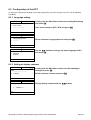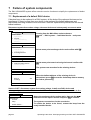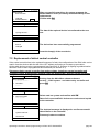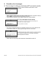
1
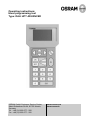
Operating instructions:
Hand programming tool
Type: DALI HPT ADVANCED
OSRAM GmbH Costumer Service Center
Albert-Schweitzer-Str.64, 81735 Munich,
Germany
Tel. : +49 (0) 1803 677 - 200
Fax : +49 (0) 1803 677 - 202
www.osram.com
www.osram.de
Contents
1
Function of the hand programming tool (HPT) ................................................................................................. 3
1.1
Overview of displays and controls............................................................................................................. 3
1.2
Basic operation of the HPT ....................................................................................................................... 4
1.3
Setting up a connection to the central controller ....................................................................................... 5
2 Starting up the lighting control system.............................................................................................................. 6
2.1
Starting up the DALI side .......................................................................................................................... 6
2.2
Start up the radio side ............................................................................................................................... 8
3 Light control with the HPT ................................................................................................................................ 9
4 Additional functions and menu options........................................................................................................... 11
4.1
Control and motion detection .................................................................................................................. 11
4.2
Deleting radio components / changing radio functions............................................................................ 12
4.2.1
Deleting channels / changing single radio functions. ....................................................................... 12
4.2.2
Deleting radio transmitters completely ............................................................................................. 13
4.3
Changes in the DALI system................................................................................................................... 14
4.3.1
Change grouping ............................................................................................................................. 14
4.3.2
Adding a new DALI device to the system......................................................................................... 16
4.3.3
Changing the ballast address and group assignment of a DALI device ........................................... 17
5 Special functions ............................................................................................................................................ 18
5.1
Controlling several rooms with one central controller.............................................................................. 18
5.2
Protect lighting scenes ............................................................................................................................ 19
5.3
System Reset.......................................................................................................................................... 19
6 System settings.............................................................................................................................................. 20
6.1.1
Manual dimming speed (FadeRate)................................................................................................. 20
6.1.2
Fade time between lighting scenes and light values (FadeTime).................................................... 21
6.1.3
Behavior after return of mains voltage (PowerOn-Level) ................................................................. 21
6.1.4
Behavior on loss of DALI control voltage (System Failure-Level) .................................................... 22
6.2
Configuration of the HPT......................................................................................................................... 23
6.2.1
Language setting ............................................................................................................................. 23
6.2.2
Setting of display contrast................................................................................................................ 23
7 Failure of system components ....................................................................................................................... 24
7.1
Replacement of a defect DALI device ..................................................................................................... 24
7.2
Replacement of defect central controller................................................................................................. 25
8 Possible error messages................................................................................................................................ 26
8.1
Error messages in setting up a link between HPT and central controller ................................................ 26
8.2
Error messages at radio startup .............................................................................................................. 26
8.3
Error messages in radio-addressing ....................................................................................................... 27
8.4
Error messages for lighting regulation..................................................................................................... 28
8.5
Error messages in reading DALI devices information ............................................................................ 28
9 Notes.............................................................................................................................................................. 29
10
Overview of the menu structure.................................................................................................................. 30
11
Notes on radio operation ............................................................................................................................ 31
12
Technical data ............................................................................................................................................ 32
page 2
Operating instructions: Hand programming tool DALI HPT ADVANCED
1
Function of the hand programming tool (HPT)
The battery-operated HPT is necessary for start up, configuration, testing a and modification of a DALI
ADVANCED lighting control system.
The HPT is used for configuration of the electronic DALI control gears (=DALI devices) and allows the
integration of radio components such as wall transmitters and sensors.
For additional information please take a look at the operating manuals for the central controller
type DALI RC ADVANCED CI respectively at the manuals of the corresponding radio
components.
1.1 Overview of displays and controls
LC-Display
Cursorbuttons
HPG On/Off,
activate display lighting
Switch on /off
lighting
Input
confirmation
Dimming
up/down
Cancel entry and
back to last menu
Number
buttons
0...9
Battery
charge status
Radio link
indication
0-0
MAIN MENU
Lighting control ..
Service ..
Setting.
> Startup ..
Cursor
position
Operating instructions: Hand programming tool DALI HPT ADVANCED
Help line
page 3
1.2 Basic operation of the HPT
The main menu gives you access to all the other menu options.
The basic operating principle is the same in all menus:
Main control panel:
ON
+
OFF
-
1. All the connected DALI devices can be operated directly from the main menu
even without prior addressing or programming (broadcast mode).
2. Operation of the selected device, group or lighting scene.
Cursor control
and Direction buttons up and down.
1. Moving cursors in the menus
2. Direct selection of device numbers, short- or group addresses and lighting scenes in
the value fields
Direction button left: Delete last entry
Direction button right: Cross-reference to the specified menu
OK – button
OK
Confirm selection or entry
ESC – button
ESC
1. Abort the selected function (press short)
2. Return to previous menu (press long)
Numeric keypad
0 ... 9
Enter numerical data in the value fields
Dimming buttons
+
Fade to maximum brightness, if already switched on.
-
Fade to minimum brightness, if already switched on.
On / Off button / display lighting
Switch on/off the HPT (hold down button for about 2 seconds). With the
HPT switched on, the display lighting can be switched on. If the HPT is
not used for about 10 seconds, the display lighting is automatically
switched off to preserve the battery.
page 4
Operating instructions: Hand programming tool DALI HPT ADVANCED
1.3 Setting up a connection to the central controller
Before a DALI system can be started up or operated with the aid of the HPT, the central controller and
the HPT must be connected to one another by a radio link. When it is switched on, the HPT sends a
special connection setup signal to all the central controllers within its range. All central
controllers within connection distance respond with their identification number. A list of central
controllers and their identification numbers will be displayed after some seconds. Then the desired
central controller can be selected and controlled or configured.
Steps in connection setup
Switch on the HPT.
INFO
Version
xxxx
Language
English
>: DEUTSCH
ESC
SCAN
CONNECTING
controller ..
found:
For about 3 seconds a initial screen with the software version
and the selected language will be displayed.
As long as the initial screen is displayed, the menu language
can be changed with the button directly between German
and English.
X
ESC
CONNECTING
> Controller (12345)
Controller (56789)
OK: CONNECT
>: BLINK
SCAN
CONNECTION
to controller
The HPT searches for central controllers within connection
distance.
During this process the message SCAN will be visible in the
upright corner of the display. The number of central controllers
that are already found is displayed. If its sure that only one
central controller exits the further search process can be
terminated by ESC.
Subsequently the display shows a list of central controllers
found. With the buttons a central can be selected. To
check whether the correct central is selected, blinking of all
fixtures connected to the selected central can be initiated with
the button. If the desired central is found, confirm selection
with OK.
After the connection setup was successfully, a verification
message with the software version of the central controller will
be displayed for some seconds.
SUCCESSFUL
Version x.x
0-0
MAIN MENU
> lightcontrol ..
service ..
setting/Einstellung
start-up ..
Then the main menu is called up.
The antenna symbol for radio reception is displayed in the
header line. If the radio link to the central controller threatens to
break down the antenna symbol will flash. If the link is lost the
symbol will disappear, the message "no RF connection to
controller" will appear and the HPT will switch off.
For possible error messages during connection setup see Section 8
Operating instructions: Hand programming tool DALI HPT ADVANCED
page 5
2
Starting up the lighting control system
As already mentioned, the system consists of a DALI side and a radio side.
Before you put the system into operation you should take a little time to think about the functions that
the system and the controls are going to perform.
For large rooms we recommend you to make a diagram of the group assignments and enter the
individual addresses of the devices.
Considerations on the DALI side
- How should the groups be assigned?
- Which lighting scenes are to be set up in the room?
- Which groups should be controlled by sensors?
Considerations on the radio side
- How many controls should be provided?
- What functions should be assigned to the individual controls?
- Where should the controls and sensors be positioned?
- Is the radio link of all components secure?
(Further information you’ll find in the manuals of the corresponding products)
2.1 Starting up the DALI side
If the radio connection to the central controller is established, it is best to check whether all the
connected DALI devices can be switched with the ON/OFF buttons and can be faded with the + / –
buttons of the HPT. By testing the installation this way, possible faults of the wiring can be determined.
When a DALI system is put into operation for the first time, all the connected DALI devices have to be
initialised and assigned to groups.
Initiate a DALI start up
0-0
MAIN MENU
lightcontrol ..
service ..
setting/Einstellung
> start-up..
4-0
STARTUP
> DALI
Radio
Select Startup with the buttons resp. and confirm
selection with the OK button.
Select DALI with the buttons resp.
and confirm selection
with the OK button.
!Attention!
When DALI is started up, all settings already made are deleted. This also applies to any devices
already programmed. If you only want to do some changes in an existing installation it is better
to proceed as described in chapter 4.3. If possible, the startup process should always be carried
out to the very end. You can abort startup by holding down ESC at any time. An aborted DALI
start up can be resumed by the menu point New device described in chapter 4.3.3. The DALI
side of the lighting control system is independent of the radio side, so radio components that
have already been "learned" are not deleted.
page 6
Operating instructions: Hand programming tool DALI HPT ADVANCED
4-1
DALI START-UP
initiate
start-up?
! CAUTION !
System will be cleared
1: YES
ESC
4-1
DALI START-UP
search device…
All the connected DALI devices are faded to the minimum
lighting level.
The system is searching for the first DALI device
4-1
DALI START-UP
device found!
program?
OK
Button 1 initiates the start up process.
When the device is found the lamp connected to it flashes.
Press OK to start the programming of this device. Should
the fixtures be programmed in a special order (e.g.
corresponding to the mounting place), the actual blinking
device can be skipped with the ESC –button and
programmed later on.
ESC: SKIP
4-1
Should the programming be proceeded, a value field
appears for entering the group address the fixture should
belong to.
Enter number of group (1 to 16) and confirm entry with
OK.
4-1
The group number entered XX and an automatically
generated ballast address YY are displayed. Desired group
number and ballast address can by selected and edited with
the cursor control. Programming is started with the OK
button (it is urgently recommended to note the group resp.
ballast address of every device for documentation of the
installation.)
4-1
If programming is successful the device is switched to
maximum level.
Subsequently a search for the next device is carried out.
After the last device has been programmed, the lighting will
flash briefly and then switch to the minimum dimmer setting.
4-1
At the end of the startup routine a message appears giving
the number XX of programmed devices.
DALI START-UP
group
:
DALI START-UP
group
ballast address
: XX
: YY
> program device
DALI START-UP
device
is programmed…
DALI START-UP
initiate
completed!
XX devices
KEY
Operating instructions: Hand programming tool DALI HPT ADVANCED
page 7
2.2 Start up the radio side
During the start up of the radio side all buttons or rocker switches of the control elements are
individually learned and assigned a function. Also the sensors a learned to the system and assigned to
a group.
Initiate the radio start up
4-0
START-UP
DALI ..
> Radio ..
4-2
RADIO START-UP
wait for
channel operation...
ESC
Use the cursor to select the Radio option and confirm with
the OK button.
The central controller now waits for a radio telegram from a
radio transmitter. This is sent by pressing the button that
should be learned for a longer time or by inserting the
batteries in a sensor. (For further details please have a look
at the instruction manuals of the corresponding
transmitters)
4-2
RADIO START-UP
wall transmitter
found
channel 1
OK: LEARN
ESC
After successful reception of radio telegrams the transmitter
type (here: Wall transmitter) and the functional type (here:
channel 1) is displayed. Press OK to learn this transmitter or
reject it and wait for next transmitter with a short press on
ESC.
(Radio start up can be aborted at any time pressing ESC for
a longer time)
4-2
RADIO START-UP
> controls group
controls broadcast
controls scene
Dependent of the transmitter type or of the radio telegram
type a menu choice is displayed. Here a selection is made
whether group-, broadcast- or scene-control is linked with
the corresponding radio telegram. The according menu
point is selected with the cursors and confirmed with OK. At
controls group and controls scene the desired group or
scene number has to be entered and confirmed with OK on
the next screen
4-2
RADIO START-UP
channel learned
connection setup
device no. XX
KEY
Finally, a confirmation window appears.
XX indicates the system-internal assignment number of the
radio transmitter. (it is urgently recommended to note the
number of each radio device that it can be unlearnt in case it
is damaged or lost. )
For possible error messages during connection setup see Section 8
page 8
Operating instructions: Hand programming tool DALI HPT ADVANCED
3
Light control with the HPT
The lighting can be controlled centrally (all devices) or groupwise with the HPT, as it is possible with
other control elements (e.g. a remote control). In addition the light level of every luminaire can be
adjusted individually. A lighting situation achieved in this way can be stored and recalled as so called
light scenes.
0-0
Select menu point lightcontrol in the MAIN MENU with the buttons and confirm selection with OK.
1-0
For controlling a group select group with the buttons
and press OK.
MAIN MENU
> lightcontrol ..
service ..
setting/Einstellung
start-up..
LIGHT CONTROL
> group
scene
all devices
individual
1-1
LIGHT CONTROL
> group
The desired group is seleced by entering the group number
and confirmation with OK.
>: SCENE
1-1
LIGHT CONTROL
group
> brightness:
>: SCENE
Subsquently the cursor jumps to the point brightness. Now
the brightness level (0–100%) for this group can be entered.
After confirmation with OK the group changes to the
corresponding brightness. With the buttons menu line
group can be accessed again and next group can be
adjusted as described. With the button the scene menu
can be accessed directly
1-2
Should the actual lighting situation be stored as scene, the
desired scene number (1-15) is entered here and confirmed
with OK.
LIGHT CONTROL
scene
:
>:GROUP
1-2
Select the entry store scene with the cursor buttons and confirm storage with OK.
LIGHT CONTROL
scene
:
call up scene
> store scene
With the button it is possible to go back to Group control
menu directly.
>:GROUP
1-2
LIGHT CONTROL
scene
:
> call up scene
store scene
>:GROUP
By the menu point call up scene previously stored scenes
can be recalled.
Note :
The fading time between scenes can be adjusted as
described in section 6.1.
Operating instructions: Hand programming tool DALI HPT ADVANCED
page 9
1-0
With menu point all devices in the lighting control menu, the
whole installation can be controlled . Please select the
corresponding line with the cursors and confirm
selection with OK.
1-3
The cursor jumps to the brightness entry automatically Now
the brightness value (0 – 100 %) can be entered and
confirmed with OK.
The whole lighting will change to the entered level.
LIGHT CONTROL
LICHTSTEUERUNG
Gruppe
group
Szene
scene
> all
Zentral
devices
Individual
individual
LIGHT CONTROL
all devices
> brightness:
1-0
LIGHT CONTROL
group
scene
central
> individual..
With the menu point individual in the LIGHT CONTROL
menu individual fixtures can be controlled. For this select
the corresponding entry with the cursor buttons and
press OK.
1-4
LIGHT CONTROL
> ballast address
For selection of the desired luminaire the ballast address is
entered and confirmed with OK.
brightness:
1-4
LIGHT CONTROL
ballast address 1
> brightness
Following the cursor changes to the menu point brightness
automatically. Now the brightness level (0 – 100 %) can be
entered and confirmed with OK.
The luminaire will change to the entered brightness.
Beside the described central, groupwise and individual percental demand, brightness
can -in each case- also be directly adjusted by the + / - fading buttons or On/Off
buttons of the HPT.
page 10
Operating instructions: Hand programming tool DALI HPT ADVANCED
4
Additional functions and menu options
4.1 Control and motion detection
If a combined light and motion sensor or a light sensor is linked for to a group (see chapter 2.2), the
control of brightness can be enabled or disabled as well as a set value for the corresponding group can
be programmed with the control menu
0-0
LIGHT CONTROL
scene ..
all devices
individual ..
> control ..
Call up the control submenu from the main menu and press
OK to confirm.
1-5
Enter the number of the group (1 to 16), that should be
regulated and confirm with OK.
CONTROL
> group
1-5
CONTROL
group: XX
> change set value
control
ON [OFF]
The actual brightness level can be stored as set value for the
corresponding group by selection of the depicted menu
entry and confirmation with OK.
1-5
CONTROL
The next transmitted brightness value measured by the
sensor will be stored as new set value.
Note:
This procedure can take up to 90 seconds.
wait for
light value ..
ESC
1-5
CONTROL
The successful acquisition of a new set value is displayed.
You can press any button to return to the CONTROL menu.
set value
changed!
KEY
1-5
CONTROL
group: XX
change set value
> control
ON
The actual setting (ON/OFF)of the regulation is displayed. To
change the current setting, select menu point control and
enable the regulation of the corresponding group with the
buttons 1, or ON or disable it with 0, or OFF
Return to LIGHT CONTROL menu by pressing ESC.
For further information concerning light regulation please take a look at the instruction
manuals of the combined light and movement sensor type DALI LS/PD ADVANCED or
the light sensor type DALI LS ADVANCED.
Operating instructions: Hand programming tool DALI HPT ADVANCED
page 11
4.2 Deleting radio components / changing radio functions
If functions of channels are to be changed, these channels must first be deleted with the Service menu
and then "reprogrammed" with the new functions as described in chapter 2. 2.
4.2.1 Deleting channels / changing single radio functions.
0-0
Call up the service submenu from the main menu and press
OK to confirm.
MAIN MENU
lightcontrol ..
> service ..
setting/Einstellung
start-up..
2-0
Select submenu RF addressing and press OK to confirm.
SERVICE
DALI system
DALI grouping ..
> RF addressing ..
2-3-0
RF ADDRESSING
> unlearn channel
delete device
2-3-1
RF ADDRESSING
wait for
channel operation
To delete a function of a radio transmitter, select menu
option unlearn channel and press OK to confirm.
The central controller now waits for a radio telegram from a
transmitter that indicates the function to be unprogrammed.
Now press the corresponding button of the handheld or wall
transmitter or remove the batteries of a sensor and replug it
after approx. 10s..
ESC
2-3-1
RF ADDRESSING
wall transmitter
found
The telegram reception is displayed with the transmitter type
and channel number as in the example depicted here.
Confirm with OK to unlearn and the channel and the
assigned function or otherwise cancel process with ESC.
channel 1
OK: UNLEARN
ESC
2-3-1
RF ADDRESSING
channel unlearned
connection deleted
device no XX
The completion of the unlearn is indicated by the following
screen.
Press any button to continue.
KEY
page 12
Operating instructions: Hand programming tool DALI HPT ADVANCED
4.2.2 Deleting radio transmitters completely
With the device number of a transmitter all channels and functions can be deleted. If the device number
is unknown it is recommend to unlearn one channel first, as described in the previous chapter, where
the device number is displayed automatically.
2-3-0
To delete a radio transmitter and all its channels from the
central controller, select menu option Delete Device and
press OK to confirm .
2-3-2
Next, enter the device number and press OK to confirm.
Press any button to continue
Confirm security inquiry with OK or cancel process with
ESC.
RF ADDRESSING
unlearn channel
> delete device
RF ADDRESSING
device
delete all allocations?
2-3-2
RF ADDRESSING
device
XX
If the process is successfully finished, the depicted message
is displayed .
deleted!
KEY
For possible error messages during connection setup see Section 8
Operating instructions: Hand programming tool DALI HPT ADVANCED
page 13
4.3 Changes in the DALI system
4.3.1 Change grouping
In a DALI system that has already been put into operation, further devices can be added to or removed
from the other groups via the Service .. menu..
0-0
Select submenu service... in the MAIN MENU with the
buttons and confirm selection with OK.
MAIN MENU
lighting control ..
> service ..
setting/Einstellung
start-up..
2-0
SERVICE
DALI system ..
> DALI grouping ..
RF addressing ..
Select DALI grouping and press OK.
Remove / add single group members
2-2-0
Select menu point edit group and confirm with OK.
2-2-1
Enter the relevant group (1-16) and confirm with OK.
The selected group is switched to maximum lighting level; all
other groups dim down to the minimum lighting level.
DALI GROUPING
> edit group
delete group
DALI GROUPING
group
:
2-2-1
If a further device is to be added to the group, select the add
device menu option . If a device should be deleted from the
group select entry delete device.
Confirm selection with OK.
DALI GROUPING
group
: XX
> add device
delete device
2-2-1
DALI GROUPING
group
: XX
> ballast address :
OK: ADD (DELETE)
page 14
The first assigned ballast address is automatically displayed
and can be accepted by pressing OK.
After a short delay the device with the displayed ballast
address will flash. If a different device is to be accessed, use
the buttons to call up the next assigned ballast address.
With OK the device is added to or deleted from the group.
Operating instructions: Hand programming tool DALI HPT ADVANCED
Deleting a whole group
2-2-0
If a complete group is to be deleted, select the option delete
group and confirm with OK.
2-2-2
Enter the number of the group that should be deleted and
press OK.
The selected group fades to maximum all other devices fade
to minimum.
DALI GROUPING
edit group
> delete group
DALI GROUPING
group
:
2-2-2
DALI GROUPING
group
: XX
Confirm security inquiry with OK or cancel process with
ESC.
delete all
allocations?
2-2-2
DALI GROUPING
group
: XX
The depicted message is displayed after the group was
deleted. Press any button to continue.
deleted!
KEY
Operating instructions: Hand programming tool DALI HPT ADVANCED
page 15
4.3.2 Adding a new DALI device to the system
If a new device has been connected to the controller it can searched, programmed with a ballast
address and assigned to a group separately.
0-0
DALI SYSTEM
> individual device ..
controller ..
scene..
Select menu point DALI System at the Service menu and
subsequently the submenu individual device and confirm
selection with OK.
2-1-1-0
INDIVIDUAL
> new device
change device
exchange device
The new device will be searched…
2-1-1-1
INDIVIDUAL
device found!
program?
OK
Next Select submenu new device and press OK to confirm.
If the new device is found the lamp(s) connected to it
flashes. The programming of this new device can be started
with OK.
Note: if more than one new device was added and should the
new devices be programmed in a special order the actual
flashing one can be skipped and programmed later on.
ESC:SKIP
2-1-1-1
INDIVIDUAL
group
:
Enter the number of the group (1..16) where this new device
should be assigned to and confirm entry with OK.
2-1-1-1
INDIVIDUAL
group
: XX
ballast address : YY
> program device
2-1-1-1
INDIVIDUAL
device
is programmed ...
The group address XX and the automatically generated
ballast address YY are displayed.
Programming can be started by pressing OK.
If the automatically proposed ballast address is to be
changed, select ballast address and press OK.
Enter a different ballast address or select it with the buttons and press OK to confirm.
The new device is programmed. After successful
programming the device fades to maximum.
If no new device is found please check if it is correctly connected to the controller and
the line voltage and if it reacts to the central On/Off/Dimming functions of the HPT.
Is the connection correct, but the device is still not found, it was obviously programmed
before. In this case please follow the instructions on next page.
page 16
Operating instructions: Hand programming tool DALI HPT ADVANCED
4.3.3 Changing the ballast address and group assignment of a DALI device
The existing ballast addresses can be changed without influence to other settings (e.g. group
assignment). Ballast addresses can be allocated several times, e.g. by connecting of previously
installed devices. Nevertheless it is important for simplification of service that all ballast addresses are
used only once and are therefore unique in the system. A ballast address that was a assign to different
devices can be changed as follows.
2-1-1-0
Coming from the MAIN MENU select submenu
service .. / DALI System .. / individual device and confirm
with the OK button.
INDIVIDUAL
new device
> change device
exchange device
Select menu point change device and press OK.
2-1-1-2
INDIVIDUAL
ballast address :
If known, enter ballast address of the corresponding device
and confirm entry with OK . Otherwise select devices with
the buttons one after another until the lamp(s)
connected to the desired device flashes, confirm final
selection with OK.
2-1-1-2
INDIVIDUAL
ballast address :
XX
Select menu point allocate new address and press OK.
change
> allocate new address
2-1-1-1
INDIVIDUAL
device found!
program?
OK
ESC: SKIP
The system searches for the devices with ballast address
XX.
The lamps of the first device with this address flash. The
address of this device can now be changed by pressing OK
or skipped by ESC.
2-1-1-1
INDIVIDUAL
group:
Enter desired group number (1 to 16) and confirm with OK.
2-1-1-1
INDIVIDUAL
group
: XX
ballast address : YY
> program device
Check displayed group number and ballast address, if
necessary select entry and change it with the arrow buttons.
Start programming with the OK button.
After the programming of this device is finished, the next
device with the same ballast address is searched
automatically. The change process is terminated when the
last device with this ballast address was edited.
Operating instructions: Hand programming tool DALI HPT ADVANCED
page 17
5
Special functions
5.1 Controlling several rooms with one central controller
A lighting scene normally effects all the DALI devices and therefore all the groups of the system.
However there is the possibility of having a lighting scene, which affects only one particular group (e.g.
the fixtures of a particular room).
Example: Room no. 1 contains group 1, room no. 2 contains group 2. Lighting scenes 1 and 2 are to
apply to Room 1; scenes 3 and 4 are to apply to Room 2. Scenes 1 and 2 are therefore assigned to
Group 1 (= Room 1) and scenes 3 and 4 to Group 2 (= Room 2). This ensures that when the lighting
scenes are stored the lighting situation in the next room is not stored at the same time and is not
affected when the lighting scene is called up.
Each lighting scene can be assigned only to one group. If a room contains more than one group, a
superordinate group has to be created that contains all the devices from the other groups in the room.
The lighting scenes can then be assigned to these superordinate -groups.
2-1-0
DALI SYSTEM
individual device ..
controller ..
> scene ..
Coming from the Main Menu select submenu service .. / DALI
system .. / scene .. / combine scene and confirm selection
with OK.
In this menu each scenes can be assigned/linked to one
particular group.
2-1-3-1
Enter scene number that should be assigned to a particular
group and confirm entry with OK.
2-1-3-1
Enter desired number of desired group that should be linked
with the selected scene and press OK.
Next start programming process by pressing OK again.
COMBINE SCENE
scene
COMBINE SCENE
scene XX
> controls group
program device
Remove Scene- / Group link:
After Entry of „000“ at value field „Controls Group“ it appears „ – – – “. Set cursor to
line Program and press OK to remove existing link.
page 18
Operating instructions: Hand programming tool DALI HPT ADVANCED
5.2 Protect lighting scenes
Normally lighting scenes can be changed by the HPT, by a handheld- and a wall transmitter. If it is
desired light scenes can be protected against all changes derived from operation of wall-and handheld
transmitters.
2-1-3-2
SCENE PROTECT
All scenes
protected against
> changes ON [OFF]
Coming from the Main Menu call up submenu service .. /
DALI system .. / scene .. / Scene protect.
The actual setting will be displayed.
Select entry with OK, enable (ON) /disable (OFF) scene
protect with the buttons and or 1 and 0 .
Changing scenes with the HPT is always possible.
5.3 System Reset
If you want to delete a DALI SYSTEM completely you can do this in the Reset System menu option.
All the data of the connected system will be irretrievably deleted. This applies both to DALI devices and
to linked radio components.
0-0
MAIN MENU
lightcontrol ..
> service ..
setting/Einstellung
start-up ..
..
Coming from the Main Menu select submenu service.. / DALI
system .. / controller .. and confirm selection with OK.
2-1-2-0
Select menu point reset system and press OK.
2-1-2-2
Confirm security prompt with button 1.
CONTROLLER
read out system
> reset system
CONTROLLER
reset System
! CAUTION !
System will be cleared
1: YES
ESC
2-1-2-2
CONTROLLER
The system is deleted...
reset in progress ..
2-1-2-2
CONTROLLER
system reset
completed
KEY
After the system reset was completed the depicted message
is displayed.
Press any button to continue.
To reprogram the central controller, the HPT must now be
switched off and the connection to the central controller reestablished.
Operating instructions: Hand programming tool DALI HPT ADVANCED
page 19
6
System settings
The DALI ADVANCED system provides a possibility of configuration of important system parameters by the user,
which allow an individual adaptation of the system behavior to the requirements of the user.
0-0
Coming from the Main Menu select menu setting and press
OK.
MAIN MENU
lightcontrol ..
service ..
> setting/Einstellung
start-up ..
3-0
Select submenu DALI – parameter and press OK.
SETTING/EINSTELLUNG
HPT / HPG ..
> DALI parameter ..
6.1.1 Manual dimming speed (FadeRate)
3-2-0
DALI PARAMETER
> FadeRate
FadeTime
PowerON-Level
SystemFailure-Level
The dimming speed for manual operation dimming is given
by the ‚FadeRate’ value.
Select menu point ‚FadeRate’ and press OK.
3-2-1
DALI PARAMETER
FadeRate
value
> program device
Enter ‚FadeRate’ value between 1 (fastest) and 15 (slowest)
and confirm entry with OK.
XX
Apply setting by programming with the OK button.
FADE RATE setting
(dimming steps/sec)
0
1
2
3
4
5
6
7
8
9
10
11
12
13
14
15
not applicable
357.8
253.0
178.9
126.5
89.5
63.3
44.7
31.6
22.4
15.8
11.2
7.9
5.6
3.9
2.8
Overview : Settings for manual dinmming speed
page 20
Operating instructions: Hand programming tool DALI HPT ADVANCED
6.1.2 Fade time between lighting scenes and light values (FadeTime)
3-2-0
DALI PARAMETER
FadeRate
> FadeTime
PowerON Level
SystemFailure-Level
Select menu point ‚FadeTime’ and press OK.
3-2-2
DALI PARAMETER
FadeTime
value
> program device
The fading time is given by the ‚FadeTime’ value.
XX
FADE TIME setting
0
1
2
3
4
5
6
7
8
9
10
11
12
13
14
15
Enter ‚FadeTime’ value between 0 (fastest) and 15 (slowest)
and confirm entry with OK.
Apply setting by programming with the OK button.
Fade time in sec
<0,7
0.7
1.0
1.4
2.0
2.8
4.0
5.7
8.0
11.3
16.0
22.6
32.0
45.3
64.0
90.5
Overview : Fade time settings
6.1.3 Behavior after return of mains voltage (PowerOn-Level)
The brightness after a power failure is given by the ‚PowerOn-Level’ value.
3-2-0
Select menu point ‚PowerOn-Level’ and press OK.
DALI PARAMETER
FadeRate
FadeTime
> PowerOn Level
SystemFailure-Level
ESC
3-2-3
DALI PARAMETER
PowerOn-Level
Value
> program device
XXX
Enter ‚PowerOn-Level’ value between 1 (minimal brightness)
and 254 (maximal brightness) or 255 (last state before power
failure is reestablished) and confirm entry with OK.
Apply setting by programming with the OK button.
255: LAST VALUE
Brightness
1%
5%
10%
20%
145
170
196
Overview : Selected brightness settings after power failure
PowerOn-Level value 85
50%
229
Operating instructions: Hand programming tool DALI HPT ADVANCED
80%
246
100%
254
Last state
255
page 21
6.1.4 Behavior on loss of DALI control voltage (System Failure-Level)
The brightness after a loss of the DALI control voltage (e.g. when the control wires are cut) is given by
the ‚System Failure-Level’ value.
3-2-0
DALI PARAMETER
FadeRate
FadeTime
PowerON Level
> SystemFailure-Level
Select menu point‚ System Failure-Level’ and press OK.
ESC
3-2-4
DALI PARAMETER
SystemFailure-Level
value
> program device
Enter ‚System Failure -Level’ value between 0 (lighting
switches off) and 254 (maximal brightness) or 255 (Last state
before loss of control voltage is retained) and confirm entry
with OK.
XXX
Apply setting by programming with the OK button.
255: LAST VALUE
Brightness
System Failure-Level
value
0% (Off)
1%
5%
10%
20%
50%
80%
100%
Last state
0
85
145
170
196
229
246
254
255
Overview : Selected brightness settings after power failure
page 22
Operating instructions: Hand programming tool DALI HPT ADVANCED
6.2 Configuration of the HPT
To improve the ergonomic handling of the hand programming tool some settings of the HPT can be adjusted
individually.
6.2.1 Language setting
3-0
SETTING/Einstellung
> HPT / HPG ..
DALI parameter
Coming from the Main Menu select menu setting/Einstellung
and press OK.
Then select submenu HPT / HPG and press OK.
3-1-0
HPT
Language/Sprache
> contrast
Select submenu Language/Sprache and press OK.
3-1-1
Use the buttons to change the menu language of HPT
and press OK.
HPT
> Deutsch
English
6.2.2 Setting of display contrast
3-1-0
HPT
Language/Sprache
> contrast
Coming from the Main Menu select menu Einstellungen /
Setting and press OK.
Select submenu Contrast and press OK.
3-1-2
HPT
Change display contrast with the buttons.
< - contrast + >
KEY
Operating instructions: Hand programming tool DALI HPT ADVANCED
page 23
7
Failure of system components
The DALI ADVANCED system offers extensive service functions to simplify the replacement of defect
components.
7.1 Replacement of a defect DALI device
If devices have to be replaced in a DALI system, all the data of the replaced devices can be
transferred. If there is more than one device to be replaced the ballast addresses and
associated mounting locations must be known. Start the replacement process with the lowest
ballast address.
Disconnect system from mains voltage, demount device and subsequently reconnect mains
again.
0-0
MAIN MENU
lightcontrol ..
> service ..
setting/Einstellung
start-up ..
..
Coming from the Main Menu select submenu
service .. / DALI system .. / individual device .. and press
OK.
2-1-1-0
INDIVIDUAL
new device
change device
> exchange device
Select menu point exchange device and confirm with OK.
2-1-1-3-0
INDIVIDUAL
> search missing device
replace device
Select menu point search missing device and confirm with
OK.
The system now searches for the missing device..
2-1-1-3-1
INDIVIDUAL
device
missing!
OK: STORE
XX
When the ballast address of the missing device is
determined, press OK to transfer its backup data to memory
for further processing.
ESC
Switch of HPT, disconnect system from mains voltage, install new DALI device and
subsequently restore mains. Switch on the HPT and reestablish the radio connection to the
central controller.
2-1-1-3-2
INDIVIDUAL
remove
lamp
search device …
ESC
page 24
Select the exchange device option again, then use the buttons to select replace device and press OK to confirm.
The system now searches for the new device.
To enable the device to be found, remove the lamp from the
newly installed device.
Operating instructions: Hand programming tool DALI HPT ADVANCED
2-1-1-3-2
After successfully searching, the system suggests the
ballast address of the previously demounted faulty as the
replacement.
Confirm with OK.
INDIVIDUAL
device found!
changed
> ballast address :
2-1-1-3-2
INDIVIDUAL
The data of the replaced device is transferred to the new
one.
is programmed ...
2-1-1-3-2
INDIVIDUAL
The device has been successfully programmed.
device
changed
KEY
Insert the lamp(s) of the new device.
7.2 Replacement of defect central controller
If the central controller has to be replaced because of a fault, the configuration of the DALI side can be
read in from the devices with the aid of the HPT without performing a new start-up procedure.
All the radio devices must be reprogrammed (see Section 2.2). Sensors for lighting regulation/motion
detection must be also reprogrammed and activated (see Section 4.1).
Disconnect faulty central controller from mains voltage, install new central controller and
reconnect mains. Subsequently establish radio link between HPT and new central controller
and perform the following steps.
2-1-0
Coming from the Main Menu choose submenu
service .. / DALI system .. and select entry controller and
press OK.
DALI SYSTEM
individual device ..
> controller ..
scene ..
2-1-2-0
CONTROLLER
> read out system
reset system
Select read out system and confirm with OK.
Data of all connected DALI devices are read out and copied
to the controller.
2-1-2-1
CONTROLLER
system read out
XX devices
The depicted message is displayed to confirm successful
data transfer to the controller.
Press any button to continue
KEY
Operating instructions: Hand programming tool DALI HPT ADVANCED
page 25
8
Possible error messages
8.1 Error messages in setting up a link between HPT and central controller
The HPT could not establish a radio link to a central
controller.
CONNECTING
no controller
available
KEY
•
•
Reduce distance between HPT and central controller and repeat connection setup by
pressing OK, if necessary replace weak batteries in the HPT.
If the connection setup fails, check supply voltage at the central controller.
4-2
RADIO START-UP
8.2 Error messages at radio startup
The transmitter channel just activated exists already as a
connection in the central controller.
channel not learned
already exists!
Press any button to continue
KEY
•
If you want to change the function of a transmitter channel, it has to be ‘unlearned’ first
as described in chapter 4.2.1 and programmed again with the new function.
4-2
RADIO START-UP
channel not programmed
memory full
If all 200 channels that could be stored in a central controller
are occupied the depicted error message is displayed.
Press any button to continue.
KEY
•
Please delete all unnecessary radio components as described in section 4.2
page 26
Operating instructions: Hand programming tool DALI HPT ADVANCED
4-2
RADIO START-UP
channel not learned
control exists!
If a light sensor or presence detector is to be assigned to a
group that is already being regulated by another light sensor
or presence detector, the depicted message will appear.
Press any button to continue.
KEY
•
4-2
RADIO START-UP
channel not programmed
all circuits occupied
Only one sensor can be assigned to each group.
If eight light sensors or presence detectors have already
been programmed and an attempt is made to train a further
light sensor or presence detector, this error message is
displayed.
Press any button to continue.
KEY
•
A maximum of 8 sensors can be linked to one central
controller.
8.3 Error messages in radio-addressing
2-3-1
RF ADDRESSING
chann. not unlearned
connection unknown
If a channel is to be unprogrammed that has not been
programmed in the central controller, the depicted message
will be displayed.
Press any button to continue.
KEY
2-3-2
RF ADDRESSING
device
1
not deleted!
device is HPT
If an attempt is made to delete the HPT currently connected
to the central controller, the message alongside will appear.
You cannot delete an HPT.
Press any button to continue.
KEY
2-3-1
RF ADDRESSING
device
not deleted!
device unknown
XX
If an attempt is made to delete a transmitter that has not yet
been programmed, the message alongside will appear.
Press any button to continue.
KEY
Operating instructions: Hand programming tool DALI HPT ADVANCED
page 27
8.4 Error messages for lighting regulation
1-5
A sensor has not yet been assigned to this group.
CONTROL
control
not possible!
Press any button to continue.
KEY
8.5 Error messages in reading DALI devices information
2-1-2-1
CONTROLLER
! CAUTION !
system error
If the transmission routine detects an error in the DALI
SYSTEM, a new startup process must be carried out.
Press any button to continue.
XX devices
KEY
2-1-1-3-1
INDIVIDUAL
no missing
device found!
A missing device could not be found when searching for a
missing device in the exchange device menu option.
Press any button to continue.
KEY
•
Ensure the device that should be replaced isn’t still connected to the central controller.
page 28
Operating instructions: Hand programming tool DALI HPT ADVANCED
9
Notes
Operating instructions: Hand programming tool DALI HPT ADVANCED
page 29
10 Overview of the menu structure
Main menu
1–0
lightcontrol
group
scene
all devices
individual
control
1–1
1–2
1–3
1–4
1–5
2–0
service
2–1–0
2–1–1–0
2–1–1–1
2–1–1–2
2–1–1–3
2–1–2–0
2–1–2–1
2–1–2–2
2–1–3–0
2–1–3–1
2–1–3–2
2–2–0
2–2–1
2–2–2
2–3–0
2–3–1
2–3–2
3–0
3–1–0
3–1–1
3–1–2
3–2–0
3–2–1
3–2–2
3–2–3
3–2–4
4–0
4–1
4–2
page 30
DALI system
individual device
new device
change device
exchange device
controller
read out system
reset system
scene
combine scene
scene protect
DALI grouping
edit group
delete group
RF Addressing
unlearn channel
delete device
Setting
HPT
Language
contrast
DALI Parameter
Fade Rate
Fade Time
Power On Level
System Failure Level
Startup
DALI
radio
Operating instructions: Hand programming tool DALI HPT ADVANCED
11 Notes on radio operation
The central controller is partly operated by radio signals. A non-exclusive transmission path is used for
radio transmission, which means that interference cannot be ruled out. Radio transmission is not
suitable for safety applications, such as emergency shutdown or calls to the emergency services. The
range of a transmitter depends on the nature of the building :
Dry material
Wood, plaster, plasterboard
Brick, MDF
Reinforced concrete
Metal, metal grating, aluminium
cladding
Penetration
approx. 90 %
approx. 70 %
approx. 30 %
approx. 10 %
This radio system may only be connected to other communication networks if this does not
infringe the relevant telecommunication laws.
This radio system may not be used for communicating beyond property boundaries.
If operated in Germany, the regulations contained in Official Bulletin Vfg 73/2000 must be
met.
The central controller may be operated in all EU and EFTA states.
Operating instructions: Hand programming tool DALI HPT ADVANCED
page 31
12 Technical data
General
Power supply:
Batteries:
6 V DC
4 x Mignon, Alkaline (LR 6, AA)
Operating time:
Approx. 24 hours, without illumination;
automatic shutdown after
approx. 30 minutes of idle time
Display:
LCD with 128 x 64 pixels
with display lighting;
automatic shutdown of the display lighting after
approx. 10 seconds of idle time
Dimensions (W x H x D):
(81 / 100 x 211 x 26 / 45) mm
Weight:
282 g
Temperature range:
5°C to +55°C
Per central controller the HPT handles:
16 lighting groups
15 lighting scenes
64 DALI devices
max. of 200 radio channels of which
max. of 8 light sensors or presence detectors
Radio system
Transmission frequency:
433.42 MHz, ASK
Range:
Normal operation
Programming mode
max. 100 m (in the open)
max. 5 m
PTT approval:
LPD – D (SRD = short range device)
Digital Addressable Lighting Interface
The international digital interface standard for the lighting industry
LMS 04091003gb
Edition 08/2004 / ADVANCED Hand Programming Tool version 2.0
Subject to change without notice. Errors and omission excepted
page 32
Operating instructions: Hand programming tool DALI HPT ADVANCED