1
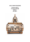
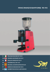
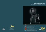
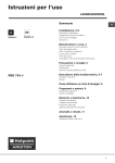
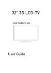
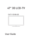
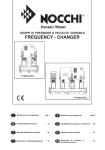
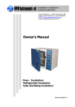
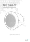
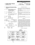
USE AND MAINTENANCE
Preziosa 80/12
Preziosa 80/16M
80/12 L
80/16M L
INDEX
1. Introduction . . . . . . . . . . . . . . . . . . . . . . . . . . . . . . . . . . . . . . . . . . . . . . . . . . . . . . . . 21
ATTENTION . . . . . . . . . . . . . . . . . . . . . . . . . . . . . . . . . . . . . . . . . . . . . . . . . . . . . . . . 21
1.1
1.2
1.3
Using the manual . . . . . . . . . . . . . . . . . . . . . . . . . . . . . . . . . . . . . . . . . . . . . . . . . . . . . . . . . . . . . 21
Warnings. . . . . . . . . . . . . . . . . . . . . . . . . . . . . . . . . . . . . . . . . . . . . . . . . . . . . . . . . . . . . . . . . . . . 21
Starting the coffee machine . . . . . . . . . . . . . . . . . . . . . . . . . . . . . . . . . . . . . . . . . . . . . . . . . . . . . 21
2. Technical characteristics . . . . . . . . . . . . . . . . . . . . . . . . . . . . . . . . . . . . . . . . . . . . . 22
2.1 SEMIAUTOMATIC . . . . . . . . . . . . . . . . . . . . . . . . . . . . . . . . . . . . . . . . . . . . . . . . 22
2.2 AUTOMATIC . . . . . . . . . . . . . . . . . . . . . . . . . . . . . . . . . . . . . . . . . . . . . . . . . . . . 22
3. Description of the machine . . . . . . . . . . . . . . . . . . . . . . . . . . . . . . . . . . . . . . . . . . . 23
4. Diagram of water feed system . . . . . . . . . . . . . . . . . . . . . . . . . . . . . . . . . . . . . . . . . 24
5. Installation . . . . . . . . . . . . . . . . . . . . . . . . . . . . . . . . . . . . . . . . . . . . . . . . . . . . . . . . . 25
5.1
5.2
5.3
5.4
5.5
5.6
Equipment provided . . . . . . . . . . . . . . . . . . . . . . . . . . . . . . . . . . . . . . . . . . . . . . . . . . . . . . . . . . .
Water mains set-up. . . . . . . . . . . . . . . . . . . . . . . . . . . . . . . . . . . . . . . . . . . . . . . . . . . . . . . . . . . .
Water softener (optional) . . . . . . . . . . . . . . . . . . . . . . . . . . . . . . . . . . . . . . . . . . . . . . . . . . . . . . .
Installation of water systems. . . . . . . . . . . . . . . . . . . . . . . . . . . . . . . . . . . . . . . . . . . . . . . . . . . . .
Drainage . . . . . . . . . . . . . . . . . . . . . . . . . . . . . . . . . . . . . . . . . . . . . . . . . . . . . . . . . . . . . . . . . . . .
Electrical connections . . . . . . . . . . . . . . . . . . . . . . . . . . . . . . . . . . . . . . . . . . . . . . . . . . . . . . . . . .
25
25
25
26
26
26
6. Operating . . . . . . . . . . . . . . . . . . . . . . . . . . . . . . . . . . . . . . . . . . . . . . . . . . . . . . . . . . 27
6.1
6.2
6.3
6.4
6.5
6.6
6.7
6.8
6.9
6.10
6.11
6.12
6.13
Filling the boiler. . . . . . . . . . . . . . . . . . . . . . . . . . . . . . . . . . . . . . . . . . . . . . . . . . . . . . . . . . . . . . .
Calibration of pump pressure . . . . . . . . . . . . . . . . . . . . . . . . . . . . . . . . . . . . . . . . . . . . . . . . . . . .
Calibration of water pressure in the boiler . . . . . . . . . . . . . . . . . . . . . . . . . . . . . . . . . . . . . . . . . .
Heating the water in the boiler . . . . . . . . . . . . . . . . . . . . . . . . . . . . . . . . . . . . . . . . . . . . . . . . . . .
Cup heater . . . . . . . . . . . . . . . . . . . . . . . . . . . . . . . . . . . . . . . . . . . . . . . . . . . . . . . . . . . . . . . . . .
Steam delivery . . . . . . . . . . . . . . . . . . . . . . . . . . . . . . . . . . . . . . . . . . . . . . . . . . . . . . . . . . . . . . .
Hot water delivery . . . . . . . . . . . . . . . . . . . . . . . . . . . . . . . . . . . . . . . . . . . . . . . . . . . . . . . . . . . . .
Preparation of ground coffee . . . . . . . . . . . . . . . . . . . . . . . . . . . . . . . . . . . . . . . . . . . . . . . . . . . .
Brewing coffee . . . . . . . . . . . . . . . . . . . . . . . . . . . . . . . . . . . . . . . . . . . . . . . . . . . . . . . . . . . . . . .
Draining the boiler. . . . . . . . . . . . . . . . . . . . . . . . . . . . . . . . . . . . . . . . . . . . . . . . . . . . . . . . . . . . .
Automatic operation - programming the coffee brewing cycles . . . . . . . . . . . . . . . . . . . . . . . . . .
Important information on daily maintenance. . . . . . . . . . . . . . . . . . . . . . . . . . . . . . . . . . . . . . . . .
Alarms. . . . . . . . . . . . . . . . . . . . . . . . . . . . . . . . . . . . . . . . . . . . . . . . . . . . . . . . . . . . . . . . . . . . . .
27
27
28
28
28
28
28
28
28
28
29
29
29
7. Instructions for authorized installer gas fired boiler (optional). . . . . . . . . . . . . . 30
7.1
7.2
7.3
7.4
Connection to gas supply . . . . . . . . . . . . . . . . . . . . . . . . . . . . . . . . . . . . . . . . . . . . . . . . . . . . . . .
Venting the combustion fumes . . . . . . . . . . . . . . . . . . . . . . . . . . . . . . . . . . . . . . . . . . . . . . . . . . .
Ignition . . . . . . . . . . . . . . . . . . . . . . . . . . . . . . . . . . . . . . . . . . . . . . . . . . . . . . . . . . . . . . . . . . . . .
Changing the calibration . . . . . . . . . . . . . . . . . . . . . . . . . . . . . . . . . . . . . . . . . . . . . . . . . . . . . . . .
30
30
30
30
8. Information for users in the european community . . . . . . . . . . . . . . . . . . . . . . . . 32
9. Guarantee. . . . . . . . . . . . . . . . . . . . . . . . . . . . . . . . . . . . . . . . . . . . . . . . . . . . . . . . . . 32
10. Declaration of Conformity . . . . . . . . . . . . . . . . . . . . . . . . . . . . . . . . . . . . . . . . . . . . 32
11. Problem solving . . . . . . . . . . . . . . . . . . . . . . . . . . . . . . . . . . . . . . . . . . . . . . . . . . . . 33
Codice manuale: 7770.039
Revisione 06/2008
1. Introduction
m
ATTENTION
• Before using the machine, carefully read all of the instructions contained in this machine.
1.1 Using the manual
m
• This manual contains all information required for the installation, use and maintenance of the
coffee machine.
1.2 Warnings
m
• Do not operate the machine or carry out routine maintenance before reading this manual
• This machine is designed and built for serving espresso coffee, hot water (for the preparation of
beverages and infusions) and steam (used to heat liquids). The use of the machine for any other than
its intended purposes is considered to be improper and unauthorized. The manufacturer declines
any liability for damage resulting from the improper use of the machine.
• The user must be a responsible adult, who is expected to comply with local safety rules and accepted
common sense procedures.
• The machine must never be used with the fixed and/or mobile guards removed or with the safety
devices cut off. The safety devices must absolutely never be removed or tampered with. The panels
covering the machine must not be removed, as the machine contains live parts (there is the risk of
electric shock).
• Strict compliance with the routine maintenance instructions of this manual is required for a safe
and efficient operation of the appliance.
• In the event of problems or breakage of any component of the espresso coffee machine, contact an
authorized service centre and insist on original spare parts from LA SAN MARCO SPA.
• If the power cord is damaged, it must be replaced by the manufacturer , the manufacturer’s technical service or a similarly qualified person so as to prevent any sort of risk.
• The user must never perform any operation for which he/she is unauthorized or lacks
training. Contact the manufacturer for any information, spare parts or accessories.
1.3 Starting the coffee machine
Ambient temperature:
Water pressure:
Water hardness:
5 ÷ 45°C (drain the water system in case of frost)
80 ÷ 800 kPa (0.8 ÷ 8.0 bar)
less than 5 °f H
21
2.Technical characteristics
2.3 SEMIAUTOMATIC
2.4 AUTOMATIC
POWER IMPUT (W)
MODEL
N°
GR.
BOILER
CAPACITY
(L)
CONNECTION MAINS
Monofase
Trifase
MOTOR
PUMP
WEIGHT
(kg)
WIDTH
(mm)
FUND
(mm)
HEIGHT
(mm)
80-PREZIOSA 12 - 2
2
12
3000-4500
3000-4500
-
80
780
530
855
80-PREZIOSA 12 - 3
3
19
5500-7000
5500-7000
-
89
970
530
855
80-PREZIOSA 16M - 2
2
12
3000-4500
3000-4500
-
80
780
530
855
80-PREZIOSA 16M - 3
3
19
5500-7000
5500-7000
-
89
970
530
855
Standard:
Hot water and steam delivery.
Steam powered coffee cup heater.
Voltages: 400 V - 3N threephase; 230 V - 3 threephase; 230 V
monophase.
Automatic level control (automatic charging of water in boiler).
External pump (300 W).
Optional accessories:
Gas firing.
Water softener (manual or automatic).
22
3. Description of the machine
18
18
5
3
12
2
1
13
4
14
11
15
17
16
6
7
8
9
10
23
4. Diagram of water feed system
26
25
28
27
24
23
31
14
32
34
33
22
21
29
30
36
35
38
37
Key to illustrations
1.
2.
3.
4.
5.
6.
7.
8.
9.
10.
11.
12.
13.
14.
15.
16.
17.
18.
21.
24
Main switch
Main switch indicator light
Steam spout
Cup warmer valve (steam)
Steam valve lever
Selection button for single strong coffee
Selection button for single normal coffee
Selection button for double strong coffee
Selection button for double normal coffee
Continuous servine push button
Hot water valve lever
Espresso coffee serving unit
Filter holding cup with handle
Manual boiler water filling lever
Hot water spout
Boiler pressure 3 bar
Visual level indicator
Manual servine push button
Boiler discharge valve
22. Automatic level control valve
23. Button valve
24. Automatic level control valve
25. Non return and safety valve
26. Automatic level solenoid
27. Pressure switch
28. Pressure switch setting screw
29. Grounds collecting tray
30. Drain pipe
31. Water softener
32. Water softener feeling pipe
33. Mains water supply tap
34. Mains water supply pipe
35. Pump feeding pipe
36. Machine feeling pipe
37. Motor pump
38. Pump pressure 20 bar
5. Installation
m
• The installation must be carried out by authorized La San Marco technical personnel.
• The coffee machine is delivered in a suitable packing. The packing contains the machine and its accessories, the user manual and the conformity declaration. After opening the packing, check the proper
condition of the coffee machine and its components. In case of doubt, do not use the appliance, and
contact La San Marco S.p.A.
• All of the packaging must be carefully conserved in case the machine needs to be transported in the future.
• The machine should be placed on a perfectly horizontal plane sufficiently sturdy to support the weight of the
machine, with a sufficient clearance around it to dissipate the heat generated during its operation.
• Do not install the espresso coffee machine in places where cleaning is likely to be carried out with jets of
water. Do not immerge the unit in water to clean it.
• For safety against hazards related to electrical currents, keep the machine away from sinks, tubs, aquariums,
taps, and areas that are wet or where water may splash.
• The machine creates heat. Therefore it needs to be placed in a room that is sufficiently ventilated to ensure heat
dissipation. Keep the machine away from sources of direct heat.
• Make sure that the voltage of the power socket does not differ from that indicated on the technical data
and on the identification tag on the machine. If the voltage is different, do not connect the machine. This may
be dangerous and may damage the unit.
5.1 Equipment provided
The machine packing contains the equipment kit, which includes the following items:
- FIlter cups with filter restraint ring
- Filters for filter cups (single and double doses)
- blind filter for filter cup
- spouts for filter cups (single and double doses)
- press for ground coffee
- braided 900mm with stainless steel tube for water connection (water supply - water softener)
- rubber drain hose with steel coil for water drain
- 3/8” nipples for hose connection to water supply tube
- cleaning brush for serving units
- Pump suction filter (on request).
- braided 600mm with stainless steel tube for water connection (pump inflow - water softener)
- braided 1600mm with stainless steel tube for water connection (pump outflow – coffee machine)
5.2 Water mains set-up
FEEDING LINE
Bring the water feeding tube (of at least 3/8” diameter) up to the machine and install an on-off valve (preferably
of 3/8” ball type) that allows a rapid opening and closing operation.
DRAIN LINE
Provide an inspectable drainage pit on the floor connected with the sink drainage line, suitable for receiving the
machine gravity drainage tube. The drain tube must be positioned so that the water ~ ows out freely, without
possibility for the pipe to clog up during the operation.
5.3 Water softener (optional)
The water softener for softening the mains water can be manual or automatic, depending on customer’s request.
m
Before connecting the water softener to the coffee machine, the resins contained in it should be
washed off as described in the user’s manual supplied with the appliance.
Note:
The water softener is considered an essential device to guarantee a proper operation of the espresso coffee machine. A water softening system should be provided in order to guarantee the efficiency, performance and duration
of the components in the machine.
25
5.4 Installation of water systems
y
32
35
Figure 1
Figure 2
1. Use the braided 900 mm stainless–steel tube 32 to connect the water supply on-off valve to the water softener inflow valve 1 (figure 3).
2. Use the braided 600 mm stainless–steel tube 35 to connect the pump intake with the water softener valve
(figure 3-4).
3. Use the braided 1600 mm stainless–steel tube 36 to connect the pump outflow with the nipple 5 of the water
system on the machine (figure 4-5).
36
Figure 3
35
35
Figure 4
36
Figure 5
5.5 Drainage
Connect the drainage tube to the grounds collecting tray and to the water drainage system.
5.6 Electrical connections
Instructions for a proper electrical connection of the espresso coffee machine:
• Before connecting the unit to the electrical mains, make sure that the data on the data plate corresponds to the electrical mains.
• The tag is located on the left side of the machine (and can be accessed by removing the lower
tray).
• The electrical system provided by the client must comply with current standards. The power socket
must be equipped with a working earth connection. LA SAN MARCO SPA will not in any way be
held liable if legal requirements are not met. An improper installation can cause injury or damage
for which the manufacturer cannot be held liable.
• For the electrical connection, it is necessary to install an omnipolar main switch upstream of the
power supply; this switch should be rated according to the electrical characteristics (power and
voltage) shown on the rating tag. The omnipolar switch must disconnect the power supply with a
contact gap of at least 3 mm.
• If it is necessary to use adapters, multiple plugs and extensions, only products meeting applicable
safety standards must be used.
• To avoid any overheating of the power cable, unwind it completely.
m
• The coffee machine must be started by qualified technical personnel approved by La San Marco.
• Once the electric and hydraulic connections are completed, the user is urged to start the espresso
coffee machine with the following procedure in order to avoid damaging the appliance.
26
• Connect the power cord to the electrical mains as shown in the attached diagram:
LEVA 2/3/4
Note:
NOTE:
*The power
La potenza
absorbed by electric
assorbita delle
heating elements
resistenze elettriche
can be reduced to
può essere ridotta a
2/3 by eliminating
2/3 eliminando uno
one of the black
dei
due fili NERI.
wires.
N
230V MONOFASE
BLU
NERO
NERO
MARRONE
GI / VE
L
L3
N
L3
L2
L1
400V-3N TRIFASE
BLU
NERO
NERO
MARRONE
GI / VE
230V-3 TRIFASE
L2
L1
BLU
NERO
NERO
MARRONE
GI / VE
3 RESISTENZE
BLU
NERO
NERO
MARRONE
GI / VE
BLU
NERO
3 RESISTENZE
MARRONE
NERO
GI / VE
6. Operating
6.1 Filling the boiler
Checking the position of the taps in the water system
a) Remove the coffee ground collection tray with grille. Now, check for the following configuration :
Boiler drain tap 21 closed
Tap on the automatic level control 24 open
Tap on the automatic level control 22 open
b) Install the coffee ground collection tray with grille
c) Open the main water fill tap 33
d) Open a steam delivery lever 5 to allow air to escape from the system as the boiler is filled.
Machine mod. 80– 12/16M - 2-3
a. Make sure that the main switch 1 is in position “zero”
b. Press and hold down the button 14 until the sight glass 17 is ¾ full.
6.2 Calibration of pump pressure
a. Once the boiler is filled, turn the main switch to position 2 (the heating elements start to heat the water).
b. Press the continuous-feeding push button 18 for the manual serving machines or the push button 10 for
the electronic machines with automatic serving, so that the water flows out of the unit corresponding to the
pressed button.
c. Read the water pressure value on the pressure gauge
38. The optimum pressure is 9 bar. The pressure is
PUMP SCREW
adjusted to the desired value by operating on the pump
screw: the pressure is increased by turning clockwise;
it is decreased by turning counter clockwise. As shown
in the figure, there are three different cases for adjusting this screw, depending on the pump installed on the
machine:
- adjust only the screw
- adjust the screw and lock it with the lock nut
- unscrew the cap nut and adjust the screw.
27
6.3 Calibration of water pressure in the boiler
a. After having filled the boiler to the proper level, turn the main switch to position 2 (the heating elements will
start to heat the water).
b. Open the lever-controlled steam valve 5 to vent the air during the heating phase. Close the valve as soon as
the steam phase is reached. The steam pressure in the boiler can be read on the upper scale of the pressure
gauge 18 from 0 to 3 bar. The pressure rises to the calibration value of the pressure switch 27 in the range
from 0.9 to 1.1 bar. To vary the steam pressure, turn the screw 28 on the pressure switch 27. The pressure
is decreased by turning the screw clockwise and it is increased by turning the screw counterclockwise. The
screw is adjusted by means of a screwdriver inserted into the hole on the lid of the pressure switch. The
pressure switch can be reached from the upper tray and grill.
6.4 Heating the water in the boiler
a. Rotate the main switch to position 2
b. Hold down a steam delivery lever 5 to allow air to escape from the system as the machine heats up. Release
the lever as soon as steam escapes from the delivery pipe. Boiler pressure is indicated on the 0- to-3-bar scale
on the pressure gauge 16 (suggested value: 0.9-1.2 bar).
6.5 Cup heater
The cup heater is used to increase heating of the upper cup support surface. Use the tap 4 to activate or deactivate the cup heater.
6.6 Steam delivery
This function is used to deliver steam from the boiler to heat liquids, or to foam milk for cappuccinos. Lower or
raise the lever 5 to obtain the maximum flow of steam. Move the lever sideways to the left of right to obtain a
reduced steam flow.
6.7 Hot water delivery
The lever-operated tap 11 is used to deliver hot water from the boiler for making tea, camomile herb tea, etc.
This lever operates in the same way as the steam delivery lever.
6.8 Preparation of ground coffee
Make sure that the filter with the desired capacity has been installed in the filter holder. After the coffee has
been loaded and pressed into the filter, the coffee level in the filter must just touch the spray head on the brewing unit. To check for correct coffee level, install the full filter holder onto the brewing unit and then remove the
holder. Now, look at the surface of the coffee: if the level is correct, the coffee will contain the imprint of the
central mounting screw on the spray head of the brewing unit.
6.9 Brewing coffee
Semiautomatic models: 80–Preziosa 12
Once the filter holder has been installed onto the machine, simply press the switch 18 to actuate the pump and
solenoid valve. When the coffee in the cup has reached the desired level, move the switch.
Automatic models: 80–Preziosa 16M
Once the filter holder has been installed onto the machine, press one of the five brewing buttons. The first two
buttons 6 and 7 are used to select the two pre-programmed single portions of coffee. The second two buttons
8 and 9 are used to select the two pre-programmed double portions of coffee. The fifth button 10 immediately
shuts down brewing if pressed during a coffee brewing cycle. Button 10 can also be used to brew the desired
quantity of coffee manually: press this button to start brewing, and presse the button a second time to stop
brewing when the desired quantity of coffee has been obtained.
6.10 Draining the boiler
If the boiler must be emptied, shut off the power to the machine by moving the main switch 1 to the “zero” position. On gas-fired machines, extinguish the flame by closing the gas feed valve. Open the drain tap 21 until the
boiler has been completely drained.
Important: be sure to close the tap before refilling the boiler.
28
6.11 Automatic operation - programming the coffee brewing cycles
Automatic models: 80–Preziosa 16M
a. Entering the programming mode
Set the main switch 1 on the machine to position “zero” (machine switched off).
Hold down the fifth button 10 on the first brewing unit. Now, rotate the main switch 1 to position 1 (machine switched on).
After a few seconds, release the button 10. The indicator led for the button will now begin to flash, as will the same led
on all the other brewing units. The machine is now ready for programming.
b. Programming
To program the four portions on brewing unit I, proceed as follows: place the single-portion filter into the single-portion
filter holder. Use the coffee dispenser to dispense a single portion of coffee into the filter. Mount the filter holder
onto brewing unit I.
Place an espresso cup under the spout on the filter holder.
Press the first button 6 whose portion is to be programmed. When the coffee in the cup reaches the desired
level, press the fifth button 10 to stop brewing.
Follow the same procedure to program the other portions on each group. Once the four portions on brewing unit I
have been programmed as desired, the relative data can be transferred to the other brewing units by pressing
the fifth button 10 on each unit. When each button 10 is pressed, the indicator led for the button will stop flashing
and remain steadily lit. This shows that the data on brewing unit I has been transferred successfully.
c. Exiting from the programming mode
After you have finished programming the machine, press the button 10 (with flashing led) on brewing unit I and
all the leds will turn off. The programmed quantity of coffee will now be delivered when an automatic brewing
button is pressed.
6.12 Important information on daily maintenance
To keep your espresso machine in top operating condition and obtain maximum performance, the following cleaning
operations must be performed on the brewing units at the end of the work day:
a. Install the blank filter (without holes) into the filter holder. This filter is provided with the machine.
b. Install the filter holder with blank filter onto the brewing unit to be cleaned but do not tighten the holder, thus
allowing water to overflow at the sides. Push the continuous brewing button and let the water run for about a
minute. This will clean the spray head and the water delivery pipe in the unit.
c. Tighten the filter holder onto the brewing unit so that water can no longer overflow at the sides. Manually run the
unit once again for around 5 seconds, and then shut the unit down. Repeat this operation 5 or 6 times to clean
the solenoid valve and the drain pipe on the unit.
Note: To clean the brewing units more thoroughly, the blank filter can be filled with one of the special detergents that
are available on the market.
6.13 Alarms
Led on the first button of pushbutton array indicates a malfunction on the flow meter.
A flashing Led on the second button of all the pushbutton arrays indicates a malfunction on the automatic boiler
refill A flashing system (jammed solenoid valve, insufficient water from the main water system, etc.). After 1 ’30”, the
pump motor will shut down.
Note: If the machine shuts down as described above, call your local service technician.
m
• Do not use water sprays, steam or similar cleaning methods. Before cleaning or maintenance operations, DISCONNECT THE CABLE IF POSSIBLE; OTHERWISE, SHUT OFF THE OMNIPOLAR
MASTER SWITCH INSTALLED AHEAD OF THE MACHINE.
• If power cable is damaged, it must be replaced with the specially prepared, original equipment
replacement part which conforms to safety regulations.
• Special maintenance, parts replacement, long-term shutdown and displanting operations must be
performed by LA SAN MARCO service personnel.
29
7. Instructions for authorized installer
gas fired boiler (optional)
Read the instructions before installing and using the appliance.
m
This appliance can only be installed and used in permanently ventilated places according to UNICIG 7129 and UNI-CIG 7131 Standards.
7.1 Connection to gas supply
Position the appliance as described in the Use and Maintenance Manual, remove the control panel as described
in the same handbook, and connect the appliance to the gas supply mains, or LPG bottle (G30/G31), using
rigid metal pipes or flexible metal tubes according to UNI-CIG 9891 Standards. Check that the appliance is
prearranged for the type of gas actually being used; the corresponding setting is shown on the settings tag.
If the appliance is prearranged for a different type of gas, change the arrangement as described in the paragraph “Changing the calibration”.
The gas infeed, consisting of an on-off valve (51), includes a G 1/8” threaded connection (thread is not gastight)
according to ISO 228-1 Standard.
If using rigid metal pipes for connection to the gas supply, place an appropriate fitting between the valve and
the rigid metal pipe, which should be provided with a G 1/8” female thread (thread is not gas-tight) according
to ISO 228-1 Standard.
If using flexible metal tubes for connection to the gas supply, interpose an appropriate G 1/2” female nipple
(gas-tight thread) according to ISO 7-1 Standard and a G 1/2” male nipple (thread is not gas-tight) according
to ISO 228-1 Standard; interpose a suitable gas-tight gasket.
When the connection is completed, open the gas flow upstream of the appliance and, using a soapy solution
(never a free flame), check the perfect tightness of the connection.
7.2 Venting the combustion fumes
In relation to the venting of the combustion fumes, the appliance is of Type A1: i.e., it draws in the air required
for combustion from the room and discharges the fumes in the same environment.
Place particular attention to the volume of the room where the appliance is to be installed: this should be at
least 12 m3.
If the room has a smaller volume, it will be necessary to install the appliance directly under a suction hood, and
also to provide a combustion air intake with a free-flow cross section of al least 100 cm2.
7.3 Ignition
Press and turn the gas valve knob (51) counterclockwise to the position of the flame symbol, as shown in Fig.
B. While holding the knob pressed, push a few times the burner ignition button, marked with the star symbol
(53) to ignite the burner (piezoelectric ignition).
When the flame is lit, check through the relative hole (54), while keeping the gas knob pressed for 5-10 seconds. After this period, if the flame does not remain lit, repeat the ignition operation again.
7.4 Changing the calibration
The appliance is prearranged to operate with the gas indicated in the relative settings tag attached to the appliance. The information regarding the air setting, injector, rated and reduced heat flow are shown in Tables
1 and 2. The data that correspond with each model are indicated by the next-to-last character of the code for
the relative model. For example, the model code shown on the tag for the gas part characteristic 80-16M-3-G
shows number 3 in the next-to-last digit.
In this case, refer to the data shown in Tables 1 and 2, respectively, in the column headed “3 Units”. If
you wish to change the calibration of the appliance, proceed as follows:
Unscrew the primary air adjusting ring nut (55 - Fig. C) to expose the nozzle (56). Using the relative wrench,
unscrew the nozzle (56) and replace it with the proper one indicated in Table 2, checking that the diameter
marked on the same nozzle corresponds to the right diameter.
30
Screw on the new nozzle (56), and position the primary air adjusting ring nut (55 - Fig. C) according to the
indications of Table 1, using a gauge or equivalent instrument to set the distance “L”, and tighten the screw
provided to fasten the nozzle.
Turn the main switch (1) to position 1, so as to connect a single heating element (50% of the boiler’s electric
power for single-phase heating element with 2 elements and 1/3 of power for heating elements with 3 elements
with three-phase connection), and ignite the burner as in the procedure described above. When the water
contained in the boiler reaches the preset temperature, the gas flow regulator will automatically decrease the
flow to the value corresponding to the reduced rated heat flow. At this point, turn the flow regulation screw
(58) so as to have a steady flame licking the sensitive thermocouple element (52), and turn the screw (57)
to obtain the maximum desired pressure value in the boiler.
After having verified the proper operation, replace the settings tag on the appliance with the one for the new
type of gas that is provided with the standard kit containing the newly installed gas nozzle. Safety devices
on appliance (manually reset).
The appliance is provided with two safety devices that shut off the gas flow if the flame accidentally goes out.
1 - Thermocouple (52): The thermocouple operates on the valve (51), whose probe (52) must be licked by
the flame from the burner (50). If the probe is not enveloped by the flame, the gas flow will be automatically
shut off.
2 - Thermostat (59): The thermostat, placed in contact with the boiler, operates on the valve (51); when the
thermostat sensor on the boiler reads 140˚C, the gas flow will be automatically shut off.
The burner can be re-ignited with the procedure described above only after the boiler body has cooled to
110˚C. Following the activation of one of the two safety devices, try re-igniting the burner with the procedure
already described.
If the malfunction persists, and the burner consequently continues to go off, contact the nearest authorized
Service outlet, which will provide to eliminate the cause of the malfunction.
31
8. Information for users in the european
community
Pursuant to European Directive 2002/96/EC on electrical waste (WEEE), users in the European
community are advised of the following.
• The symbol with the crossed-out dustbin on the appliance or its packaging indicates that at the end of the
product’s life cycle, it must be collected separately from other waste.
• Suitable separate collection of the equipment for subsequent recycling, treatment and disposal contributes
to preventing possible negative consequences for the environment and health, and favours the recycling of
materials that the unit is made of.
• In accordance with European Directive 2002/96/EC, abusive disposal of the product by the user will result in
application of penalties as set forth by local law.
9. Guarantee
The warranty becomes void if:
• The instructions in this manual are not complied with.
• The scheduled maintenance and repairs are carried out by unauthorized personnel.
• The machine is used for any other than its intended purposes.
• The original parts are replaced with parts from different manufacturers.
• The warranty does not cover damage caused by neglect, use and installation not in compliance with the
recommendations of this manual, improper operation, abuse, lightning and atmospheric phenomena, over
voltage, over current, or insufficient or irregular power supply.
10. Declaration of Conformity
The manufacturer:
La San Marco S.p.A.
34072 Gradisca d’Isonzo (GO) Italy – Via Padre e Figlio Venuti, 10
phone (+39) 0481 967111 – fax (+39) 0481 960166 – http://www.lasanmarco.com
declares under its own responsibility that the espresso coffee machine described in this manual and identi~ ed
by the data on the tag located on the machine, is compliant with directives 98/37/EC, 73/23/EC, 89/336/EEC,
89/109/EEC. For verification of compliance with said directives, the following harmonized standards have been
applied: EN 121 00-1, EN 121 00-2, EN 60335-1, EN 60335-2-75
Gradisca d’Isonzo, June 2007
Managing director
Mr Roberto Marri
32
11. Problem solving
PROBLEM
CAUSE
SOLUTION
1. The boiler is full of water and
the water flows out of the
safety valve.
• One of the outflow lines from the • Check the autolevel circuit, the manual charging
boiler or from a circuit of the unit
button, and the boiler heat exchangers.
has a leak.
• Replace worn or damaged parts to eliminate
the leak.
2. The safety valve trips in
and vents the steam.
• Malfunction of electrical system • Check the wiring that feeds the heat-ing ele(the electrical heating element
ment and the pressure switch.
is always connected).
• In the machines with electronic temperature
• Pressure increase in the boiler
control, check the proper operation of the elec(the safety valve trips in at 1.9tronic control unit, the triac, the level probe, and
2.5 bar).
the elettrical wiring.
3. The machine was started prop- • The electric heating element is • Check if the heating element is con-nected to
erly but the water in the boiler
defective or is not connected.
the power supply.
does not warm up.
• Check if the heating element safety thermostat
has tripped in and check its proper operation.
• In the machines with electronic temperature
control, check the proper operation of the electronic control unit, the triac, the level probe, and
the elettrical wiring
4. There is no water flowing from • Coffee ground too fine or ex- • Adjust the grinding coarseness and/or the quana serving unit.
cessive quantity for type of filter
tity of ground coffee.
used.
• Check that the injector, the upper circulation
tube, the spray nozzle and the solenoid of the
• Clogged water circuit.
unit are not clogged.
• Defective solenoid.
• In the machines with electronic metering, check
the displacement meter and its valves.
• Check the solenoid of the unit, its wiring and
the fuse in the electronic control unit.
5. The programmed servings of • Abnormal operation of the elec- • Program the serving quantities separately on
espresso coffee are not contronic control unit or of the diseach serving unit. If the problem persists, restant or vary on the dif- ferent
placement counters.
place the displacement meter of the serving
units.
unit affected.
• Leak from serving unit solenoid
• Replace the solenoid valve of the serving
valve.
unit.
6. It is not possible to pro- gram • Abnormal operation or defective • Check the control unit-displacement meters
the serving quantities on unit 1
displacement meter of unit 1.
electrical wiring.
and to copy them on the other
• Replace the displacement meter.
units.
7. Displacement meters alarm.
• Displacement meters jammed • Replace the displacement meter.
• Check the wiring and its connections, the conor defective.
trol unit and the fuses.
• Defective wiring.
8. Autolevel alarm.
• Lack of water in the autolevel • Check the hydraulic circuit of the autolevel.
circuit.
• Check if the on-off valve on the water supply
is open.
• Main water supply valve
• Replace the autolevel solenoid.
closed.
• Faulty autolevel solenoid.
9. The machine is switched on • The electric wiring of the elec- • Check the electrical wiring, the electronic con(the main switch is in position
tronic control unit is defective.
trol unit and its components.
1 or 2 and the signal light is lit) • The electronic control unit is • Replace the electronic control unit.
but the electronic control is out
defective.
of order.
33
PROBLEM
CAUSE
SOLUTION
10. The machine feeds water from • Solenoid and/or pump fed continu- • Short-circuited control unit relay.
one serving unit although the
ously.
• Replace the electronic control unit.
serving has not been selected.
11. 85 S models: one unit serves • Electric circuit of unit improp- erly • Check the connection and correct it (see
water continuously.
connected.
wiring diagram).
12. The steamer discharges only • Worn gasket on tap.
small quantities of steam or
water droplets.
• Replace the gasket.
13. Small drops flow out of the • Worn gasket on tap.
water tap.
• Leak from solenoid.
• Replace the gasket.
• Check the solenoid and if necessary replace
it.
14. The unit emits a whistle after • Faulty operation of expansion • Check the expansion valve and if necessary
serving the coffee.
valve.
replace it. Calibrate the valve at 12 bar.
• High pump pressure.
• Check the pump operating pressure. Calibrate the pump at 9 bar.
15. The filter cup comes off the • Worn gasket under the filter cup.
serving unit.
• Replace the gasket.
• Clean the serving unit and the filter cup.
16. When coffee is being served, • Worn gasket under the filter cup.
some of it drips out of the edge
of the filter cup.
• Replace the gasket.
• Clean the serving unit and the filter cup.
17. Water leaking from the drain of • Malfunctioning unit solenoid.
• Check the unit solenoid.
the serving unit solenoid.
• Water leaking from unit cooling sys- • Check the plunger on the solenoid and
clean the solenoid.
tem.
• Replace the solenoid.
• Check the cooling tube and the seal rings
inside the unit.
18. Light cream (the coffee flows a. Coarse grinding.
out of the spout rapidly).
b. Low pressing pressure.
c. Small quantity of ground coffee.
d. Water temperature below 90°C.
e. Pump pressure above 9 bar.
a. Sprinkler filter on unit clogged.
g. Filter holes widened (filter cup).
a.
b.
c.
d.
e.
a.
19. Dark cream (the coffee drips a.
out of the spout).
b.
c.
d.
Fine grinding.
High pressing pressure.
Large quantity of ground coffee.
High percolation water temperature.
e. Pump pressure below 9 bar.
a. Sprinkler filter on unit clogged.
g. Filter holes clogged (filter cup).
a.
b.
c.
d.
e.
a.
20. Presence of grounds in coffee a. Coffee ground too fine.
cup.
b. Worn grinders in grinder-dis- penser unit.
c. Pump pressure above 9 bar.
d. Sprinkler filter on unit clogged.
e. Filter holes widened (filter cup).
a.
b.
c.
d.
21. Coffee with too little cream in • Sprinkler filter on unit clogged.
cup (spurts out of spout).
• Check and clean with blind filter or replace.
34
Finer grinding.
Increase the pressure.
Increase the quantity of ground coffee.
Increase the pressure in the boiler.
Decrease the pump pressure.
Check and clean with blind filter or replace.
g. Check and replace the filter.
Coarser grinding.
Reduce the pressure.
Decrease the quantity of ground coffee.
Decrease the boiler pressure.
Increase the pump pressure.
Check and clean with blind filter or replace.
g. Check and replace the filter.
Coarser grinding.
Replace the grinders.
Decrease the pump pressure.
Check and clean with blind filter or replace.
e. Check and replace filter.
PROBLEM
CAUSE
SOLUTION
22. The cream in the cup is too • Coffee extraction takes a long time • Clean or replace the filter.
• Clean or replace the sprinkler filter.
thin (it disappears after a few
due to clogged filter.
seconds).
• Coffee extraction too fast due to • Lower the temperature in the boiler.
clogged sprinkler filter.
• Water temperature too high.
23. Presence of depressions in the • Sprinkler filter partly clogged.
• Clean or replace the sprinkler filter.
coffee grounds (looking inside • Low amount of ground coffee for the • Adjust the amount of ground coffee.
the filter cup).
fiter used.
Note: If it is not possible to solve the problem as described above, or if other malfunctions develop, contact
the authorized La San Marco service centre.
35