1
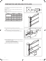
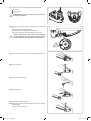
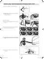
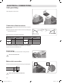
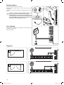
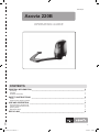
www.somfy.fr Axovia 220B Installation guide 5101723A 5101723A_Axovia-220B.indd 1 10/05/2011 15:37:50 5101723A_Axovia-220B.indd 2 10/05/2011 15:37:50 CONTENTS General information____________________________________________________ 2 Safety_ _________________________________________________________________ 2 Safety instructions 2 Product Description____________________________________________________ 3 Exploded diagram of the product Size of motor (in mm) Installation type Technical specifications Description of operation of the indicators 3 4 4 4 5 Pre-installation checks_ _______________________________________________ 5 Gate Pillars Reinforcements Area of application 5 5 5 5 Preparation and drilling of pillars____________________________________ 6 Mounting and fixing of the motors_ ____________________________________ 7 Installing the integrated opening end stop_ ___________________________ 9 Electrical connections_ ______________________________________________ 10 Cable guide fitting Connection of the two motors Aerial wiring Mains cable connection Locking the arms 10 10 10 10 11 Quick commissioning_ __________________________________________________ 12 Storing the remote controls Auto-programming the travel 12 12 operation______________________________________________________________ 13 Advanced parameter setting_ _________________________________________ 13 Activating the Automatic Closure mode Switching to sequential mode after activating Automatic Closure mode Adding and removing remote controls 13 13 13 Connecting additional devices_________________________________________ 14 Connecting the photoelectric cells Photoelectric cells - 1 set Photoelectric cells - 2 sets Orange light Key lock Interphone Exterior aerial Backup battery Area lighting Digicode 14 14 14 15 15 15 15 16 16 16 DIAGNOSTIC AND repairs_________________________________________________ 17 1 5101723A_Axovia-220B.indd 1 10/05/2011 15:37:50 General information This Somfy product must be installed by a professional motorisation and home automation installer, for whom this guide is intended. This product, installed in accordance with this guide, complies with EN 12453 and EN 13241-1 standards. It is the installer's responsibility to ensure that the automatic installation and its operation are compliant with the standards in force. The use of any safety components not approved by Somfy remains the sole responsibility of the installer. The selected safety accessories for the installation must comply with the current standards and regulations in force in the country in which the product is being installed. Moreover, the installer must comply with current standards and legislation in the country in which the product is being installed, and inform his customers of the conditions for use and maintenance for the product. Any use outside the sphere of application specified by Somfy is forbidden. This invalidates the warranty and discharges Somfy of all liability, as does any failure to comply with the instructions given herein. Hereby, Somfy declares that this product is in compliance with the essential requirements and other relevant provisions of Directive 1999/5/EC. A declaration of conformity is available on the website at www.somfy.com/ce (AXOVIA 220B), usable in UE, CH and NO. Safety Safety instructions Important safety instructions. Follow all the instructions as incorrect installation can lead to serious injury. This device is not designed to be used by persons (including children) whose physical, sensory or mental capacity is impaired, or persons with little experience or knowledge, unless they are under supervision or have received instructions on using the device by a person responsible for their safety. Check that the temperature range marked on the motors is suited to the location where the motors are to be installed. Before installing the motor, ensure that the driven part is in good mechanical condition, that it is correctly balanced and that it opens and closes correctly. The motor cannot be used with a driven part incorporating a small gate (unless the motor is inhibited when the small gate is opened). Ensure that there are no danger zones (risk of crushing, cutting, trapping) between the gate and the surrounding fixed elements caused by the opening movement of the gate. Watch the gate while it is moving. Place the fixed control devices and remote controls out of the reach of children. Any switch without a locking device must be installed in direct view of the gate and away from any mobile parts. Unless it is key-operated, it must be installed at a minimum height of 1.5 m and must not be accessible to the public. During installation of the motorisation: -- Remove any jewellery (bracelets, chains, etc.). -- For drilling and welding operations, wear special glasses and sufficient protection. -- Use the appropriate tools. -- Do not connect to the power source until installation is complete. -- Be careful when handling the motorisation system to prevent any risk of injury. After installation, ensure that the mechanism is correctly adjusted and that the protection system and any manual release mechanism operate correctly. Regularly check the condition of the gate. Gates in poor condition must be repaired, reinforced or even replaced. Check that the various motorisation component's screws and fittings are correctly tightened. Before carrying out work on the installation, switch off the power supply. In order to operate, the motor must be supplied with 230 V -50 Hz. The electric line should: - solely be used for the motor, - have a minimum cross section of 1.5 mm², - be equipped with protection (10 A fuse or breaker) and a differential device (30 mA), - be equipped with an all-pole disconnection device, - be installed in accordance with the current electrical safety standards. It is recommended that the installation be fitted with a lightning conductor (in compliance with standard NF C 61740, maximum residual voltage 2 kV). All 230 V lighting connected to the “zone lighting” output must be connected to earth or be of the double isolation type. 2 5101723A_Axovia-220B.indd 2 10/05/2011 15:37:50 Product Description Exploded diagram of the product 1 2 3 4 5 6 7 8 9 10 11 12 13 14 15 Motor Motor arm Gate leaf arm Gate leaf bracket Electronic unit Motor cover Motor cover bolt Information card Enclosure cover O-ring Cover bolt Cover key Electronic unit bolt Grommet Cable clip x2 x2 x2 x2 x1 x2 x4 x1 x2 x2 x2 x2 x1 x2 x4 16 17 18 19 20 21 22 23 24 25 26 27 28 29 30 Cable clamp bolt Earth bolt Earth washer 12x27 clamp washer Shaft bolt / motor arm HM 10x40 End stop cover bolt End stop cover End stop bolt End stop (upper part + lower part) Motor arm / gate leaf arm short shaft Gate leaf arm / bracket long shaft Gate leaf arm ring Gate leaf arm damper Aerial Cell strap x8 x1 x1 x8 x2 x4 x4 x6 x2 x2 x2 x4 x2 x1 x1 12 11 10 9 8 7 6 29 13 16 30 5 17 18 15 14 19 26 27 4 28 21 22 1 25 2 20 23 24 3 3 5101723A_Axovia-220B.indd 3 10/05/2011 15:37:51 Size of motor (in mm) 30.5 309.9 297.5 166.12 175 245 938.83 Installation type Technical data Power supply Standby power consumption Max. power consumption Average frequency of movements per day Max. thrust force at 1.25 m Operating temperature Thermal protection Index protection rating Integrated radio receiver Number of storable remote controls Motor feed outputs Power per motor Output for orange light Area lighting output Accessories supply output Backup battery input Photoelectric cell input Dry contact input 230 V - 50/60 Hz 4.5 W 600 W 20 cycles/day < 15 kg EN 12453 -20°C to +60°C Yes IP 44 Yes 16 24 V DC 120 W Flashing, 24 V, 15 W 500 W max. 24 V DC / 200 mA Yes Yes (1 or 2 sets) Yes 4 5101723A_Axovia-220B.indd 4 10/05/2011 15:37:53 Description of operation of the indicators Led 1 (On/Off) Off: On continuously: Slowly flashing: Flashing quickly: Electronics off Electronics on Gate heavy Motor thermal cut-out or short circuit on motor output Led 2 (Auto) Off: On continuously: Slowly flashing: Sequential mode Sequential mode + timed close Storing closing time Led 3 (Warning) Off: On continuously: No active input Cell or external command or radio transmission in process Led 4 (Prog) Off: On continuously: Slowly flashing: Nominal operation Initialisation Proximity sensor active Pre-installation checks Gate The gate must be in good condition: ensure that its structure is suitable for automatic control and that it conforms to the relevant standards. The gate must remain horizontal throughout its travel, and must open and close manually with ease. Ensure that the gate travels straight at ground level, and that there are no sticking points that may prevent it from sliding correctly. Pillars The pillars are untrue so require the use of an intermediate plate. Furthermore, when one of the motor clamp mounting holes is not resting on anything or is close to the angle of the pillar or wall, it is essential to use the intermediate plate (ref. 2400485). Reinforcements If the gate has no reinforcements, prepare some metal reinforcement plates (e.g.: 15x15 cm and 4 cm thick). for mounting the brackets to the gate leaves. Area of application 2m H≤2m L≤ P≤ 200 Kg 5 5101723A_Axovia-220B.indd 5 10/05/2011 15:37:54 Preparation and drilling of pillars For the indicated values, the gate leaves and their hinge pins are taken to be on the same axis. If the hinge pins are offset, the maximum opening angle values will be reduced. [1]. Measure dimension A. [2]. Select dimension B in the table according to the required opening angle. A (mm) 0 50 100 150 200 250 α max. (°) 120 110 105 100 95 90 90 90 B (mm) 205 160 150 150 150 150 150 150 [3]. Trace axis AM on the pillar copying dimension B on the pillar. [4]. Check that dimension D is greater than or equal to 435 mm. There must be no obstacles to impede the movement of the arm in this area. [5]. Check that dimension L is between 800 mm and 2000 mm. If L < 1250, the installation of a set of photoelectric cells is essential. 65 mm [6]. Trace horizontal line AH in the middle of the reinforcement, perpendicular to the rotational axis of the gate. If the gate has no reinforcements, place the motors approximately 1/3 of the way up the gate leaves from the bottom. Extend this line on the pillar until it intersects with AM. [7]. Place the template where the 2 lines intersect and drill. 6 5101723A_Axovia-220B.indd 6 10/05/2011 15:38:19 Mounting and fixing of the motors [1]. Open the upper cover using the specific key supplied. [2]. Unscrew the 2 bolts of the lower cover and remove. Info card: for improved legibility, use a permanent marker. me na me na tel tel [3]. Attach the motor, checking the level. [4]. Assemble: - the motor arm to the motor with an HM 10x40 bolt (19) - the gate leaf arm to the motor arm with the short shaft (24) Note: the gate arm can be fitted both ways. - the gate leaf bracket to the gate leaf arm with a damper (27), 2 rings (26) and a long shaft (25). 7 5101723A_Axovia-220B.indd 7 10/05/2011 15:38:21 [5]. Unlock the motor arms using the button located under the motor. : arms locked : manual operation In unlocked position, move the arms slowly to avoid damaging the motors. [6]. To ensure correct closing of the gate, push the motor arm and the gate firmly: - the gate arm must be completely unfolded, - the mounting tab must be flat against the reinforcement, - the gate arm marking must be lined up with the motor arm arrow. Ensure the markers on the motor arm and the gate arm are lined up to ensure the gate is properly closed and can withstand strong winds or external forces. [7]. Mark the centre-to-centre distances for mounting the bracket to the gate. [8]. Remove the gate arm. [9]. Drill the gate leaf reinforcement. [10]. Attach the bracket. [11]. Put the gate arm back into position. [12]. C heck that the position of the bracket on the gate is correct by manually opening the gate. If necessary, correct the position. 8 5101723A_Axovia-220B.indd 8 10/05/2011 15:38:24 Installing the integrated opening end stop [1]. Manually open the gate to the opened position α required. α max [2]. Install the end stop on the bracket side, flush against the shoulder of the motor arm. Do not tighten the end stop. [3]. Close the gate slightly. [4]. Move the end stop approximately 2 mm towards the motor arm shoulder. 2mm [5]. Tighten the end stop with a long Allen key for greater torque when tightening the end stop bolts (16 Nm). [6]. Install the end stop covers: screw the lower cover holding the shaft while performing this operation, then screw in the upper cover. A B C D E F 2 1 [7]. Permanently fix the gate leaf bracket using the central mounting hole. 9 5101723A_Axovia-220B.indd 9 10/05/2011 15:38:28 Electrical connections Cable guide fitting Fit the cable guides on the two motors. Connection of the two motors Motor M1 actuates the gate leaf that opens first and closes last, and opens for pedestrian access. OR OU [1]. With the gate closed, identify the location of motor M1 by identifying the gate leaf that will open first. M1 the left M1 is estto à gauche [2]. Connect the motors as indicated in the table below. If M1 is to the left and M2 to the right If M1 is to the right and M2 to the left connect the wire of ... connect the wire of ... M1 M2 to terminal ... blue 11 brown 12 brown 13 blue 14 M1 M2 M1 isM1 toest theà right droite to terminal ... brown 11 blue 12 blue 13 brown 14 To connect the motor without electronics to the electronic unit, use a terminal block, a connecting strip or a distribution box (not supplied) to be placed in the motor before refitting the cover. Aerial wiring For optimum performance, it is essential the aerial is correctly positioned. Do not cut the aerial wire Mains cable connection Connect the earth wire, then live and neutral according to the following table. Terminal Blue wire Neutral 17 Red/brown/black wire Live 18 Green and yellow wire Earth Ensure the wire colours are observed. 10 5101723A_Axovia-220B.indd 10 10/05/2011 15:38:30 Locking the arms [1]. Close the two gate leaves and lock the arms by pressing them. [2]. Turn the motor locking handles to the locked position . 11 5101723A_Axovia-220B.indd 11 10/05/2011 15:38:31 quick commissioning Storing the remote controls The remote controls can be programmed for full opening of the gate only or pedestrian or full opening: Full opening only: -- a brief or long press on the remote control will cause both gate leaves to open Pedestrian or full opening -- a brief press on the remote control will lead to a single gate leaf opening for pedestrian access -- a long press on the remote control will cause both gate leaves to open. To programme a remote control for full opening only [1]. Position the remote control on the target engraved on the cover. [2]. Press and hold the button to be programmed until indicator 4 light flashes slowly (indicator 3 comes on while it is pressed). [3]. Release the button; it is now programmed. To programme a remote control for pedestrian and full opening [1]. Position the remote control on the target engraved on the cover. [2]. Press and hold the button to be programmed until indicator 4 light flashes slowly (indicator 3 comes on while it is pressed). [3]. Release the button. [4]. Press the button to be programmed again (within 10 seconds) until indicator light 4 flashes slowly (indicator 3 comes on while it is pressed). [5]. Release the button; it is now programmed. Proceed in the same way for all the remote controls to be programmed. At the end of the programming cycle, only indicators 1 and 4 will be on. Auto-programming the travel Auto programming the gate's travel is essential when commissioning the motor. The gate must be closed before auto programming is started and at least one remote control must have been programmed. If the gate does not open, or moves in the direction of closing, check the motor wiring. [3]. Once both leaves of the gate are completely open, press and hold the programmed button on the remote control again. The gate closes, one gate leaf at a time. [4]. Initiate a second opening and closing cycle. This time, the two gate leaves will close at the same time. At the end of the second closing, indicator 4 will go out, which indicates the end of the auto programming phase. 11 12 133 ...... Auto-programming consists of making the gate perform two gate leaf opening and closing cycles. [1]. Move the remote control away from the receiver. [2]. Press and hold the programmed button on the remote control. The gate opens at slow speed. 14 Once both complete cycles have been carried out, save the parameter setting [1]. Press and hold the programmed button on the remote control. [2]. Press the programmed button again to stop the gate leaves halfway through their travel. [3]. Disconnect the power supply for 5 seconds then restore it. [4]. Press and hold the programmed button. The movement of the gate leaves during auto programming are always carried out at a reduced speed. The two opening/closing cycles must be complete for auto programming to take place. If the movement of the gate is interrupted during auto programming, the process is delayed and will resume next time the gate is fully opened. THE MOTOR IS READY TO OPERATE. It will operate in sequential mode by default. 12 5101723A_Axovia-220B.indd 12 10/05/2011 15:38:31 operation According to the programming of the remote controls, the gate will open either fully only (full opening only mode), or for pedestrian access or fully (pedestrian or full opening mode). The motor can operate in Sequential mode or Automatic Closure mode. Sequential mode: successive presses of the same remote control button will lead to the following movements: Open, Stop, Close, Stop, Open etc. Automatic closure mode: pressing the programmed button of the remote control will cause the gate to open. The gate will close automatically after a time delay. The length of the time delay before closing can be adjusted. The gate can be held in the opened position by giving a stop command during the time delay. To close the gate, press the remote control button again. For more information, refer to the user section. Advanced parameter setting Activating the Automatic Closure mode By default, the motor will be in Sequential mode. The automatic closure mode can only be activated if a set of photoelectric cells has been fitted, as well as an amber light and area lighting. [1]. Place a programmed remote control on the target engraved on the cover. Indicator light 2 is off. [2]. Press and hold the programmed button of the remote control until indicator 2 comes on. [3]. Release. Indicator 2 flashes. [4]. Initiate opening using the transmitter. [5]. Once the gate is completely open, wait the time required before automatic closure, then press the remote control button to send the close command. Indicator 2 will light up continuously. Switching to sequential mode after activating Automatic Closure mode [1]. Place a programmed remote control on the target. Indicator light 2 is on. [2]. Press and hold the programmed button of the remote control until indicator 2 goes out. [3]. Release. Indicator light 2 is off. Adding and removing remote controls To clear all the programmed remote controls Press the reset push button located above terminal 1 of the electronic unit for 7 seconds. when pressing the button, the 4 indicators will go out, and indicators 1 and 4 will come on again. All the programmed remote controls will be erased. To add a remote control after the first programming phase [1]. Proceed as with the initial programming phase of a remote control in full opening mode only or pedestrian and full opening mode (see page 12). [2]. Programme the gate travel again as programming a new remote control cancels the gate travel programming (see page 12). It is not possible to store more than 16 transmitters. Delete all the remote controls and resume programming. To change the operating mode of a remote control that is already programmed, Start the remote control programming procedure over again (see page 12). The most recent mode stored clears the previous mode stored. 13 5101723A_Axovia-220B.indd 13 10/05/2011 15:38:32 Connecting additional devices Connecting the photoelectric cells Photoelectric cells must be connected to use the motor in automatic closure mode. Before connecting the cells, remove the jumper between terminals 3 and 4. Photoelectric cells CE - 1 set 1 CR TC:1 Transmitter 2 3 4 5cell RC: Receiver cell 2 24 V 0 V AC/DC CE CR 24 V 0 V C NC NO AC/DC max. 20 cm 2 1 2 1 2 3 4 40 cm 5 10 m 24 V 0 V C NC NO AC/DC 24 V 0 V AC/DC Photoelectric cells - 2 sets TC: Transmitter cell RC: Receiver cell CE2 CE1 1 E2 CE1 1 2 24 V 0 V AC/DC 1 24 V 0 V AC/DC 2 2 24 V 0 V AC/DC CR1 1 2 1 24 V 0 V AC/DC 1 2 CR1 3 4 5 24 V 0 V C NC NO AC/DC 2 3 4 5 CR2 1 2 3 4 5 24 V 0 V C NC NO 24 V 0 V C NC NO AC/DC CR2 AC/DC 1 2 3 4 5 24 V 0 V C NC NO AC/DC 14 5101723A_Axovia-220B.indd 14 10/05/2011 15:38:33 Orange light Exterior aerial 5 mm 15 mm Key lock Interphone 15 5101723A_Axovia-220B.indd 15 10/05/2011 15:38:36 Backup battery Minimum charging time before first use: 48 hours Operation time: 10 continuous cycles or 24 hours with a gate in perfect working order Service life: 3 years (take worn batteries to the appropriate sites for proper disposal) If there is a power cut and the backup battery is not charged, you will not be able to open your gate. If your gate is the only entrance to your property, it is recommended you have a manual unlocking system fitted (ref 2400487). This will make it possible to enter the property and disengage the motors. Area lighting Area lighting comes on with the motor, and goes out 2 minutes after the motor has come to a complete stop. 500 W max with 230 V Digicode E E H – + H H P2 M P1 T3 C3 R3 T2 C2 R2 T1 C1 R1 V H P2 M P1 T3 C3 R3 T2 C2 R2 T1 C1 R1 V E – + H 5101723A_Axovia-220B.indd 16 + H V V H P2 M P1 T3 C3 R3 T2 C2 R2 T1 C1 R1 V 16 – H P2 M P1 T3 C3 R3 T2 C2 R2 T1 C1 R1 V E E – + H – + H V H P2 M P1 T3 C3 R3 T2 C2 R2 T1 C1 R1 V H P2 M P1 T3 C3 R3 T2 C2 R2 T1 C1 R1 V V V V 10/05/2011 15:38:40 DIAGNOSTIC AND repairs Indicators Led 1, Led 2, Led 3 and Led 4, located under the motor cover, are used to give fault finding indications. Problems Led 1 does not come on when switching on Led 3 remains on permanently Led 1 flashes slowly Led 1 flashes quickly The transmitter range is reduced Solutions -- Check the mains power supply. -- Check the supply cable. -- Check the fuse This signal indicates a cell fault. Check: -- the cell alignment -- the cell cables -- the cell power supply -- that the cells are recognised in automatic mode -- if there is no permanent control on inputs 5 or 6 of the circuit The force required of the Axovia is too much. Check the gate matches the area of application. -- Short circuit detected on the motor output. Rewire the motors to eliminate the short circuit. -- The electronics are overheating, wait 5 minutes before sending a new command. -- Check that the position of the original aerial is in line with the instructions given on p. 8. -- Check the transmitter batteries. -- Environmental disturbance (electric pylon, metal walls etc.). Use an outside aerial. -- For vehicles with air conditioning fitted with a metallic windscreen: point the remote control at the black strip on the windscreen or point through the untreated side windows, or through an open window. 17 5101723A_Axovia-220B.indd 17 10/05/2011 15:38:40 18 5101723A_Axovia-220B.indd 18 10/05/2011 15:38:40 www.somfy.fr Axovia 220B Operating guide CONTENTS GENERAL INFORMATION____________________________________________________ 2 About Somfy Assistance Declaration of Conformity 2 2 2 Safety instructions_ ___________________________________________________ 2 Caution Safety instructions relating to operation 2 2 Use and operation_ _____________________________________________________ 3 Default operation in sequential mode Operation in Automatic Closure mode Specific operation Manual back release 3 3 3 3 Recycling_______________________________________________________________ 4 5101723A_Axovia-220B.indd 1 1 10/05/2011 15:38:41 GENERAL INFORMATION Thank you for choosing a SOMFY product. This equipment has been designed and manufactured by Somfy in accordance with a quality policy complying with the ISO 9001 standard. About Somfy Somfy develops, manufactures and sells automatic control devices for domestic opening and closing systems. We offer alarm systems, automatic control devices for awnings, roller shutters, garages and gates. We guarantee all Somfy products will meet your expectations in terms of safety, comfort and time saving on a daily basis. At Somfy, the pursuit of quality is a continuous process of improvement. Somfy's reputation has been built upon the reliability of its products and the Somfy brand is synonymous with innovation and technological expertise worldwide. Assistance Getting to know our customers, listening to them, meeting their needs: this is Somfy's approach. For further information on how to choose, purchase or install Somfy systems, please ask your Somfy installer for advice or contact a Somfy advisor directly for help and assistance. As part of our policy of continuous innovation and improvement of our models, we reserve the right to make any modifications deemed necessary at any time. © SOMFY. Somfy SAS, with a capital 20.000.000 Euros, RCS Annecy 303.970.230 Declaration of Conformity Somfy declares that this product complies with the essential requirements and other relevant provisions of Directive 1999/5/EC. A Declaration of Conformity is available at www.somfy.com/ce (Axovia 220B). Product can be used in the European Union and Switzerland. Safety instructions Caution Important safety instructions. Always read this user manual and the attached safety instructions before using this Somfy product. The instructions cited in the product user manual will ensure that the safety requirements relating to property, persons, and the aforementioned standards, are met. Failure to comply with these instructions absolves Somfy of any liability resulting from damage that may be caused. Any use outside the sphere of application specified by Somfy is forbidden. This invalidates the warranty and discharges Somfy of all liability, as does any failure to comply with the instructions given herein. Safety instructions relating to operation This device is not designed to be used by persons (including children) whose physical, sensory or mental capacity is impaired, or persons with little experience or knowledge, unless they are under supervision or have received instructions on using the device by a person responsible for their safety. Watch the gate while it is moving. 1 – Never operate on a motor with a live power supply. 2–C heck the product regularly to detect any defects in balance in the gate or any signs of wear. Do not use the motor if it needs repairing or adjusting. Regularly check the condition of the gate. Gates in poor condition must be repaired, reinforced or even replaced before installation. Regularly check that the various components screws and fittings of the motor are correctly tightened. 3–N ever allow children to play near a moving gate. Do not allow children to play with the gate control devices. Remote controls must be placed out of sight and out of reach of children. 4 – Never clean the motor with high pressure water cleaning equipment. 5–D isconnect the installation from its power supply during cleaning operations or other maintenance operations. 6–B efore any maintenance operations, disconnect the electrical power supply and if necessary, remove the battery. 7–T ake care when using the manual back release. Activating the manual back release system could cause uncontrolled movement of the driven part due to mechanical faults or a loss of balance. 2 5101723A_Axovia-220B.indd 2 2 3 4 1 10/05/2011 15:38:41 Default operation in sequential mode By default, the gate will operate in sequential mode. Depending on the programming carried out by the installer, the gate can operate either in full opening mode only (systematic opening of both gate leaves), or in full or partial opening mode (pedestrian mode). In this case, a long press on the remote control button triggers full opening, and a brief press triggers partial opening of the gate. Long press Short press ppp •• "Full opening" operation (Fig. 1) 1 ppp ppp STOP ppp STOP ppp ppp •• "Partial opening" operation (Fig. 2) 2 •• Obstacle detection operation When an obstacle is detected during opening, the gate will stop. Pressing the programmed button on the remote control will make the gate move in the opposite direction. When an obstacle is detected during closing, the gate will stop and reopen automatically. If the obstacle is detected in the last 50 cm of travel, the gate will stop and not reopen. Operation in Automatic Closure mode If the Automatic Closure mode has been programmed during installation, the gate will operate as follows. Pressing the programmed button of the remote control will cause the gate to open. It will close automatically after a delay time that was defined when activating the Automatic Closure mode. It is possible to keep the gate in the open position by briefly pressing on the programmed button on the remote control during the time delay. Pressing the button on the remote control again will close the gate immediately. Specific operation Depending on the peripherals installed and the operating options programmed by your installer, the motor may have the following specific functions: •• Operation with safety cells Gate open: an obstacle placed between the cells will inhibit closing of the gate as the cells have detected a presence. Gate moving: If an obstacle is detected while the gate is opening, the gate will continue moving (cell status not recognised). If an obstacle is detected when closing, the gate will stop for 1 second and then reopen automatically. •• Operation with orange flashing light The orange light is activated during any movement of the gate with a 2 second warning. Manual back release In case of a power cut, the manual back release device makes it possible to open the gate. Unlock the motor arms by turning the button located underneath the motors. Padlock closed: arm locked; padlock open: arm unlocked, manual operation. In unlocked position, move the arms slowly to avoid damaging the motors. Use and operation 5101723A_Axovia-220B.indd 3 3 10/05/2011 15:38:43 Version 1 — 05/2011 Utilisable en UE, C Usable in EU,C Bruikbaar in EU, C Utilizable en la UE, C Nous nous réservons le droit à tout moment, dans un souci constant d’évolution et d’amélioration de nos modèles, de leur apporter toutes modifications que nous jugerons utiles. ©SOMFY. SOMFY SAS, capital 20.000.000 Euros, RCS Annecy 303.970.230 Recycling Do not throw away your scrapped equipment or used batteries with household waste. It is your responsibility to dispose of your electronic equipment in the relevant recycling points. 5101723A_Axovia-220B.indd 4 10/05/2011 15:38:43


![Notice_d``installation_Solar_Set[1] (3811 ko) - Domo](http://vs1.manualzilla.com/store/data/006325956_1-4c510b243905a1d5ce505f51f928dca7-150x150.png)