1
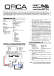
Thank you for choosing ORCA Q Products, and welcome to the power and convenience of Brushless RC. By purchasing the “SPARK” brushless Electronic Speed Control (“ESC”), you have chosen one of the most advanced speed controls. This speed control features are have simple integrated turbo. Please read this manual thoroughly to familiarize yourself with the installation, setup, operation, and limitations of this unit. By operating this product, you accept the ORCA Q Warranty Terms. SPECIFICATIONS System: Forward/Brake: Dimensions: Weight: Voltage Input: Brushless Yes (Factory preset) 34(L) x36(W) x 23(H) mm (excluding fan) 57g (Including wires) (4.8 – 9.9V DC) 4 – 6 Cells NiCD/NiMH 2Cell LiPO / 2-3 Cell LiFe 320A Yes Up to 5.5 Turns Sensorless / Sensored 540 sized brushless motors 6V / 2.0A Yes 1. Profile Select 2. Drag Brake 3. Brake Force 4. Running Mode 5. Battery Mode 6. Default Mode Peak Current: High Frequency: Motor Limit: Motor Type: B.E.C.: Multi Protection System: INSTALLATION & CONNECTORS Solder the wires to the battery pack and motor from ESC according to the following scheme : Red wire “+” post (Battery +ve) Black wire “-“ post (Battery -ve) Blue wire (A) “A” post (Motor A) Blue wire (B) “B” post (Motor B) Blue wire (C) “C” post (Motor C) (Warning: Use good quality solder and avoid soldering longer than 5 seconds per solder joint) BATTERY RED + BLACK - CH1 CH2 CH3 BAT ON OFF RADIO & ESC SET-UP Transmitter Settings: Throttle Travel Maximum / 100% Brake Travel Maximum / 100% Throttle Exponential Start with 0% Throttle Neutral Trim Center - 0 Throttle Servo Reverse Reverse (Futaba, KO, Sanwa) ※Refer to Quick User Guide if required Initial set-up of the throttle end-points of the ESC: Connect the power wires of the ESC to a fully charged battery set; making sure the polarity is correct. Bind your receiver and transmitter first if your radio requires you to do so. Turn on the transmitter Press and hold the “Set” Button using a thin stick before turning on the ESC. Release the button when the green LED lights up. PUSH the Throttle to the full brake position--- Press the “Set” Button, when hear 2 beep the LED will flash from “RED” to “GREEN” release the throttle to neutral LED will flash “RED”. PULL the Throttle to the full throttle position--- Press the “Set” Button, when hear 2 beep the LED will flash from “RED” to “GREEN” release the throttle to neutral LED will flash to “RED”. LEAVE the Throttle in the neutral position--- Press the “Set” Button, you will hear 4 beeps and the LED will flash from “RED” to “GREEN” then the LED flash to “GREEN” (if your punch is set not to Level 1, LED will change from “GREEN” to “RED”), the endpoints and neutral position of the ESC are set up successfully. There will be no need to recalibrate the ESC thereafter. After each run as long as the settings on the transmitter have not been changed. Note! If you do not hear the beeping sound as described above try reversing the throttle reverse setting in the transmitter. Motor must also be connected to hear the beeping sound. Customizing the ESC operations on the ESC Due to the different requirements of each type of racing, it is important to customize your ESC for a particular usage. Customization of the ESC is done BLUE . A BLUE . B BLUE . C A B C SENSOR WIRES Secure the on/off switch in a place where it will not be accidentally knocked to the “off” position during a crash. To avoid radio glitches, arrange for the placement of the ESC such that the power wires and the receiver antenna wires do not cross over each other. Try to arrange for the receiver placement such that the receiver plugs are easily accessible. Use supplied extension cable if plugs are not accessible – for ESC setup purposes. Position the ESC where it is protected in the event of a crash; and use the supplied double sided tape to secure the ESC onto the chassis. Install/Solder your favorite battery connector to the battery wires if you do not plan to direct solder your battery. RED to +ve and BLACK to – ve. (Warning! Reversing the battery polarity will destroy your ESC and void the warranty) Connect the 3 motor wires to the motor; you can either solder ther wires directly to the wires(A,B,C) to the labels of the taps on the motor when soldering. Avoid soldering longer than 5 seconds per solder joint and avoid shorting the motor by creating a wire bridge or a solder bridge in the solder tabs on the motor (Warning! If motor wires connected incorrectly, the wheel will move in the reverse direction.) Connect the supplied sensor cable from ESC sensor plug to the motor sensor plug. Connect the receiver plug to the CH2/throttle pin of the receiver. Connect the battery wires to a charged battery, turn the ESC switch in the Off position (Warning! Reversing the battery polarity will destroy your ESC and void the warranty) Turn on your transmitter Press the “Set” Button before turning on the ESC, hold for a few seconds until you hear a long beep and then release the button the red and green LED will flash, this is indicate that you have entered into the program menu, and press again to enter the next menu. (GREEN LED FLASH -- Indicates Program Mode, RED LED FLASH --- Indicate Value, Short Flash and beep – Indicates 1 step, Long Flash and beep – Indicate 5 steps ) When you are in the menu you want to adjust, hold the button till you hear long beep and then release, you can get into the sub-menu and see the red LED flashes and press the button to change the value. Hold the button till you hear 4 beeps that will indicate the selected parameter is confrimed on the ESC and return back to Main program menu. You can go to next main menu for setting different parameter. (Note: When confrimed the selected paramenter of vaule the program will return to main program) When all of selection is done, turn off your ESC and restart again. Multi Protection System – Other than the Low Voltage Protection and the Overheat Protection that were described above, the ESC has 2 more protections: Motor Lock Protection: The ESC is protected against damage when the motor is stuck and does not turn at all. Power will not be applied in this situation. Caution! Since the ESC relies on the feed back of the 3 motor wires to deploy this protection, it ONLY works if the motor does not turn AT ALL. If the rotor has any rotation, the ESC will consider the motor to be operational and the power to the motor will not be cut off. Fail Signal Protection: In case the radio signal to the ESC is interrupted for over 1 second during a run, the ESC will cut off until the signal resumes. Detailed Explanation of each ESC Menu items: 1. Profile Mode – Allows you to change the Profile of the ESC (PF 1 to PF 10): PF 1 is a mode dedicated for 0 Timing Class and a flashing green LED will indicate the zero timing being selected(Base on ROAR rules). PF 2 has the lowest punch and Level 6 has the highest punch. PF 2~6 will have timing but no turbo is introduced. PF 7~10 will have timing and turbo is introduced. Please note that increasing profile will also increase the heat generated to the ESC and motor. Always start with a milder setting and work your way up. Note: do not select PF10 when used 5.5T sensored motor, it may damage the ESC. 2. 3. 4. 5. 6. Drag Brake – Also know as trail braking - allows you to set the automatic brake force applied when the throttle returns to neutral position (8 steps ): 1>>>>>>>>>>>>>>>>>>>>>>>>>>>>8 (OFF>>>>>>>>>>>>>>>>>>>>>>Strong) Drag brake affects how a car handles off-throttle (entering a corner). With drag brake on, there will be more weight shift to the front tires thus increasing the front end grip when you let go the throttle. Experiment with different settings to find the setting that fits your driving style most. Brake Force – Allows you to set the maximum amount of brake during manual braking (8 steps): 1 >>>>>>>>>>>>>>>>>>>>>>>>>>>8 (Strong>>>>>>>>>>>>>>>>>>>>>>Soft) (You can also set your transmitter Brake “HI-Point” to reduce or increase your brake force.) Running Mode – there are 4 modes of operation (Forward/Brake, Forward/Brake/Reverse, Forward/Reverse, Forward/Hold/Reverse): Forward/Brake is the required for racing situation where reverse is not allowed. Both forward and brake are proportional to radio input. Forward/Brake/Reverse gives you 1 time proportional braking – i.e. when the throttle position goes from forward to brake, the ESC will apply proportional brake to the motor. Once the throttle returns to neutral from the brake position, braking again will be considered as reverse. If the motor is still moving forward at that time, an ESC preset brake force will be applied to the motor until the motor stops and reverse will be applied. Forward/Reverse does not give you control of brake force. When the throttle position goes from forward to reverse, the ESC will apply reverse to the motor. If the motor is still moving forward at that time, an ESC preset brake force will be applied to the motor until the motor stops and reverse will be applied. Forward/Hold/Reverse is similar to Forward/Brake/ Reverse. The difference is that you can brake as many times as you need. Reverse will not be applied until the motor stops. Battery Mode – Select which kind of battery you used and protected your ESC and Battery. Ni-xx 6Cell / 5Cell Li-xx 2Cell (Default) Life 2Cell / 3Cell No Cut-off protection. No protection is only recommended for serious racing application that requires every second of run time. Do NOT use this setting unless you are absolutely sure. You may ruin your battery packs in one run. Default Mode – Allows you to change all setting to factory the default 0º timing is tested to be the most efficient. OPERATING TIPS Misc. Tips: Connect the ESC to the battery pack only when you are ready to run. This will avoid draining the battery pack. Always disconnect the battery after your run. A small spark may occur at the connection when the battery is connected. This is normal and is due to the charging up of the capacitors. LIMITED WARRANTIES / REPAIR PROCEDURES All ORCA Q products are manufactured according to the highest quality standards. ORCA Q guarantees this product to be free from defects in materials or workmanship for 30 days from the original date of purchase verified by sales receipt. This limited warranty does not cover damage that are results of normal wear, misuse or improper maintenance of the product. To avoid unnecessary service and mailing charges, always eliminate all other possibilities and check all components for malfunctions before sending in your unit for repair. Products sent in for repair that operate perfectly will be charged a service fee. When sending in the product, always pack carefully and include the original sales receipt, a description of the problem encountered, your return address and contact information. Since we do not have control over the installation and use of this product, we cannot accept any liability for any damages resulting from the usage of this product. Therefore, using this product is at your own risk, and the user accepts all resulting liability from installing and using of the product. Troubleshooting Guide: SYMPTOM POSSIBLE CAUSE Continuous beeping once battery is connected (unit not turned on) Continuous Beeping once unit is turned on Motor running in reverse when accelerating forward Steering servo working, but motor not running ESC switches off frequently Radio glitches Broken signal wire to receiver Throttle setting reversed Transmitter setting changed after initial set-up; or steering/throttle moved during turn-on of ESC REMEDY Replace signal wire Reverse throttle setting Reset transmitter and recalibrate ESC Incorrect motor-wire connection Reconnect motor-wires correctly Wiring problem Check for wiring shortage at the motor tabs Overheating due to wrong motor selection or gear-mesh problem Transmitter battery too low; broken receiver antenna wire; or power wires too close to receiver ORCA Q Powered by ORCA [email protected] Change motor or check out gear-mesh Check for different causes and fix problem