1
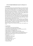
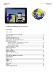
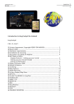
Lemon DSM2/DSMX protocol Telemetry Unit
Instructions
NOTE: These instructions are based on version 1.5 of the Lemon Telemetry unit, sales of which began
in December 2014. See “Variants” on page 11 for an overview of version differences.
These instructions are written by two users on RCGroups: jj604 and Daedalus66. We have no connection with Lemon.
Lemon and Orange are brand names. Spektrum, DSM2, DSMX, X-BUS, Airware, STi, and the Telemetry logo are Trade Marks
of Horizon Hobby. Deans and PowerBox are Trade Marks. These names are used here simply as descriptions of those items.
Overview The Lemon Telemetry unit will transmit telemetry data from the model when connected to the bind port of
most DSM2/DSMX-compatible receivers, whether Lemon, Spektrum or Orange. The unit has inbuilt
sensors for receiver voltage, temperature and altitude as well as external sensors for temperature, flight
battery current and voltage, and motor RPM.
Display of the data requires a suitable Spektrum or compatible transmitter that will show selected values
on the screen. At present the following Spektrum transmitters can receive and process the data from the
Lemon unit: DX6 (2014 version), DX7s, DX8, DX9, DX10 and DX18. In addition, the Lemon unit works
with the now-discontinued Spektrum STi Telemetry interface (SPMTR1000) for the iPhone/iPad. It may
become possible for other transmitters to display the telemetry data if equipped with a compatible
telemetry-capable module; such a unit is said to be under development by another manufacturer. The
focus here, however, is on using the Lemon unit with a Spektrum transmitter.
The first four pages of these instructions should give you what you need to get the telemetry unit up and
running. The rest of the document consists of various kinds of additional information likely to be of help
and interest to some users.
Getting Started – First Time Use Before starting you need to prepare your model, bind the receiver and set it up to work with your
transmitter as usual. Do all the normal setup of servos and mixes so that the model is ready for flight
before moving on to the telemetry setup. It is strongly recommended that you review the Telemetry section
of your transmitter manual in order to understand how the telemetry function and displays work.
This is what the basic connection to a Lemon
10ch receiver looks like.
Lemon Telemetry Instructions
And here is the same setup for a Lemon 7channel stabilized receiver.
11-Dec-14
1
Here is what it looks like with an Orange
RX3SM. Although the servo ports on this
receiver are Molex 1.25mm pitch Picoblade
connectors, the bind connector is a standard
0.1” header.
And finally, here is the Lemon unit connected
to a Spektrum AR8000 with satellite.
Connection and Binding With transmitter off and no power to the receiver, connect the telemetry unit to the receiver bind connector
using the included cable, as shown above. Orient the connector so the black wire connects to the pin
labeled “–” or “GND”.
Note that the Lemon unit does not have the equivalent of the X-BUS port found on the side of a Spektrum
TM1000 telemetry unit. You should also connect the receiver satellite(s) if used. Do not connect the
external V/I sensor or Temp/RPM sensor at this time.
Make sure you have a model memory set up in the transmitter for the receiver/telemetry unit.
You are ready to bind:
1. Put a bind plug on the telemetry bind connector.
2. Connect power to the receiver (maximum 7.2v) from either:
a. A separate receiver pack (4 or 5 cell NiMH, 2S LiFe); or
b. A separate 5V or 6V BEC; or
c. The throttle cable of an ESC with inbuilt BEC.
3. All red/orange LEDS should be flashing rapidly on the telemetry unit, receiver and satellite (if used)
to indicate bind mode. If not, locate the problem before proceeding.
4. Move the transmitter 3-6ft/1-2m away, select the appropriate model memory, place the throttle
stick in low and turn on in bind mode (see transmitter instructions for how to do this).
5. Wait until the bind is complete and the receiver and telemetry LEDs are steady.
6. Disconnect power from the receiver. Turn off the transmitter.
7. Remove the bind plug from the telemetry unit.
8. Repower the transmitter and then the receiver/telemetry unit.
Correct operation is shown by a solid red LED and flashing green LED (2x/second) on the telemetry unit.
Solid red/orange lights on receiver (and satellite) indicate a good radio link.
Lemon Telemetry Instructions
11-Dec-14
2
Configuring the Transmitter Screens – first steps The Telemetry screen on the Spektrum transmitter allows you to select which data items are recognized.
You cannot, however, choose where on a telemetry screen they appear – only whether they are there or
not. The placement is pre-programmed. Access to the transmitter’s Telemetry setup screen is from the
System Setup screen.1
Select one of the fields, then click and rotate the roller to
select the item you want displayed in that field. In the
example at right, the second field is selected and
configured to display Amps. When a field has an item
selected, clicking on that item will open a screen of options,
generally whether to display or not, alarm values if relevant
and some user variables.
Note that the FlightLog field alarms are not used by Lemon.
The Settings field allows you to set when the telemetry
screens are displayed, the units used, plus the name of
data logs and how they are started. In the Settings screen setting the Display to Roller means that you can
use the roller to scroll through the telemetry screens at any time from the normal main Transmitter display
screen; this is very convenient. Exit back to the MAIN screen when you are finished.
As explained under Signal Indicator on page 6, the “A” field under Flight Log will provide a basic measure
of signal reception.
If your receiver is powered up, properly bound, and the
telemetry unit is connected, you will see the bars logo
marked on the screen at right.
Congratulations, you have a fully functioning telemetry unit
linked to your transmitter. At a bit over an inch square
(38x26x12mm), with a total weight of 11g and only one
connection cable to the receiver, it’s a self-contained
package that’s hard to beat for convenience!
Most people, however, will want to add flight pack voltage
and current sensing capability, and that’s where we go next. Adding External Sensors The Voltage/Current sensor and/or the Temperature/RPM sensor
can now be connected to the appropriate sockets on the
Telemetry unit (with power off). The EXT socket is reserved for
future use.
After connecting an external sensor, the receiver and telemetry
unit must be re-bound to the transmitter, with the flight pack
connected in the case of the Voltage/Current sensor. Use the
same process as in Getting Started – First Time Use on page 2.
1
The examples show a DX8 transmitter. Other transmitters may have different displays, but the principles of setup are
similar.
Lemon Telemetry Instructions
11-Dec-14
3
The Voltage/Current sensor can be damaged if subjected to reverse voltage. Check the polarity of the
connections before plugging in the flight battery.
Displaying Data from External Sensors Configure the transmitter screens to show the values you are interested in from these additional sensors.
As we saw previously, there is little flexibility in the screens as they have been largely pre-configured. The
current/voltage sensor will display the instantaneous pack voltage in the Volts field and total current in the
Amps field. Alarms can be set for Min and Max values.
If the PowerBox (PBox) field is available on your transmitter, voltage can be shown to higher accuracy and
the cumulative number of mAh consumed can be displayed. If these values do not appear, check that you
have activated (Act) the PBox display in the transmitter Telemetry setup screen. Note that with the Lemon
unit there is only one set of battery voltage and capacity readings (the original PowerBox sensor unit
monitors two separate supplies) and there are NO alarms
available for PowerBox values, as these depend on the
presence of a PowerBox sensor unit. The practical outcome
is that no alarm is available for the percentage of pack
capacity used.
When plugged in, the external temperature sensor (shown at
right) automatically replaces the internal telemetry unit value
with the more accurate external probe value.
As shown, the RMP sensor uses the red wire that is included
with the temperature sensor, but not connected to it. See
“RPM” on page 7 for an explanation of the RPM indicator.
LED Signals on the Telemetry Unit Red LED
Solid = Correct data exchange with receiver. This means the telemetry unit is recognizing the transmitter
and has transferred the telemetry packet to the transmitter for display.
Flashing rapidly = The receiver is in bind mode.
Absent = No connection
Green LED
Solid = The Current sensor initialized correctly when using the hidden pot/switch. The Red LED will light
up if initialization fails (see page 8).
Flashing = The altimeter is set to provide height above ground level (AGL) data (the default). The green
LED also flashes while binding.
Absent = The altimeter is set to absolute barometric height (ASL) based on standard 101.325kPa as sealevel atmospheric pressure.
[In addition green and red flashes are used as confirmations during user calibration of Current and Voltage. See page 9. A
single quick flash of the green LED at power up identifies versions of the telemetry unit v1.5 and beyond.]
For most users a solid red LED and a flashing green LED indicate correct operation.
Lemon Telemetry Instructions
11-Dec-14
4
Additional Information Detailed information about the Lemon Telemetry Unit The Lemon Telemetry unit is not a copy of anything made by Spektrum, but an original design that
conforms to the Spektrum data transmission protocol and the DSM2/DSMX radio protocols.
The Lemon unit differs from the Spektrum TM1000 2 telemetry unit; both in construction and in the way it
provides certain data. Most obvious is that there is no display of the Fields H and F (Holds and Frame
loss), nor are there packet loss indicators for the four possible receivers: A, B, L and R. These features
are unique to Spektrum systems. In their place Lemon provide a general “Signal Indicator”, displayed in
the “A” field that provides roughly similar data on the strength and reliability of the radio link.
The unit is significantly smaller than the Spektrum one and about half the weight. It operates over an input
voltage range of 3.45 to 7.2v. (Despite the “5.5V max” written on the label.)
Specifics The Lemon Telemetry unit uses an ATmega 88PA microprocessor and a 2.4Ghz transmitter to send data
signals to your transmitter. It synchronizes with the receiver via the bind connector so that it cannot
interfere with the radio control link. It reads the receiver voltage and the number of data packets
successfully arriving at the receiver, combines those with its own data from sensors, and sends the whole
lot to be displayed on the transmitter telemetry screen. Without any additional sensors it will display
receiver voltage (RxV), signal indicator (A), accurate height above ground level (Alt), and the internal
temperature of the unit (Temp).
The unit is supplied with two plug-in sensors. The first is an accurate external temperature probe, which
automatically replaces the internal temperature when connected and can be used to monitor LiPo pack or
ESC temperature in flight.
The external temperature sensor also includes a sensor wire for measuring RPM from one of the motor
wires. Before using the RPM function, please review its limitations, as discussed on page 7.
The second plug-in sensor (available with either Deans-style T-connectors or XT60 connectors) measures
flight power pack current and voltage. The instantaneous readings are displayed on screen in the Amps
and Volts fields. In addition, on Spektrum transmitters that provide a PowerBox display, the cumulative
number of mAh drawn from the flight pack and the pack voltage at higher resolution are displayed. The
displays may vary depending on the fields chosen in Telemetry Setup in the transmitter menu and on the
capability of the transmitter itself (for example, the DX6 and DX7s do not display PowerBox).
The telemetry unit works with any Lemon DSM2 or DSMX protocol receiver that has bind connector pins.
This includes the 7-channel Stabilizer, as well as the 6-channel DSMX protocol compatible receiver, the
10-channel DSM2 protocol compatible receiver and most others. Various Spektrum and Orange receivers
have also been tested and found to work with the Lemon unit. Lemon also states that their satellites are
plug-compatible with Spektrum, but it is sensible to test the correct operation of receivers and satellites of
different brands.
The connection lead plugs into the data socket of the Lemon Telemetry unit (labeled “To Receiver Bind”)
and the bind port of the receiver, just as the Spektrum TM1000 unit does. A Y-cable can be used on the
bind pins of a Lemon stabilizer if that connector is also used for Aux2; the telemetry unit will not interfere
with the Aux2 output.
2
Spektrum also make a limited range TM1100 unit without an X-BUS port but the TM1000 is the closest comparable one to
the Lemon.
Lemon Telemetry Instructions
11-Dec-14
5
The Lemon unit does not have an X-BUS port and is not Spektrum X-BUS compatible. Nor are the threepin JST-ZH connectors (the four small white ones) wired like Spektrum. For this and other reasons,
Spektrum sensors are NOT interchangeable with Lemon sensors.
Do not interchange Lemon and Spektrum telemetry unit hardware and connectors, as the polarities
are different.
The unit has been designed on the assumption that most people will be using a 5V BEC power source.
However it will operate on a voltage of from 3.45 to 7.2V from the receiver. So in practice this power
source can be a 1S LiPo, a 4 or 5cell NiMH pack, a 2S LiFe pack, a separate 5 or 6V BEC or the internal
BEC of an ESC. It should not be used with a power supply over 7.2v, such as a 2s LiPo pack.
Accuracy and Limitations Signal Indicator The Lemon system does not report Frame Losses (F) and Holds (H) since this is data generated only by
Spektrum systems. Nor does Lemon report individual packet losses on up to four separate
receivers/satellites (A, B, L and R) as Spektrum does.
However the Lemon unit does use the “A” display for a
Signal Indicator value. This is calculated from the number
of packets lost in transmission. A reading of 100 means
that no packets have been lost in transmission, while
smaller numbers indicate losses.
The value is based on the number of packets received
about every half second. In versions of the Lemon unit to
date, it is of limited use and tends to give readings that
range between 85 and 100. Note that, as with some other
telemetry systems, if the data communication link is broken, the last known Signal Indicator value will stay
on the screen until data communication is restored.3
As noted previously, the B, L and R satellite receiver fields are not used by the Lemon system, nor are the
F (Frame loss) and H (Hold) fields. Receiver voltage is displayed on the same screen as the Signal
Strength indicator.
Height The unit includes a Bosch BMP180 integrated digital pressure and temperature sensor. Since this is used
to report altitude, the reading will vary with local barometric pressure. Accordingly, in order to display
height above ground level (AGL), which is what most people are looking for when they think of the height
of a model, the Lemon telemetry unit as delivered sets the
altitude reading to zero every time power is connected.
The Lemon altimeter is quite accurate by hobby standards. It
is ambient temperature compensated but will have small
errors due to internal noise, onboard heating of the
components, and natural variation of atmospheric pressure
during the flight. It is normal for the height reading to fluctuate
by up to 6ft/2m, and this variation may increase during
3
A forthcoming version of the telemetry unit will have an improved Signal Indicator function to give more useful and reliable
results that range from 0-100.
Lemon Telemetry Instructions
11-Dec-14
6
unusual weather conditions with rapidly changing conditions. This is an inherent behavior of a pressure
altimeter and not a fault of the unit. Display in meters or feet is chosen in the telemetry setup screen.
Flight battery current is displayed on the same screen if you have the V/I sensor connected.
Temperature The external temperature probe is accurate at room temperature to within 1˚F or better. The sensing
element is a 10kNTC thermistor, and maintains good accuracy at all temperatures. The internal
temperature reported by the unit when no external temperature sensor is plugged in may be a little higher
due to heat dissipation on the board. The reading can be displayed in ˚C or ˚F but is limited to whole
degree resolution in both.
RPM The RPM input is obtained via a single wire connected to any of the three wires of a brushless motor. The
unit detects voltage pulses from the motor wire and calculates RPM from their frequency, based on the
setting on the transmitter telemetry setup screen for the number of magnetic poles in the motor. The
display shows 1/10 of the actual RPM. That is, 1234 is actually 12,340 rpm.
If the number of poles is not available, it can be estimated by comparing RPM displayed with the reading
from an optical tachometer while the motor is running; the pole number can be adjusted to get agreement.
Lemon suggests that the gear ratio adjustment provided on the Spektrum transmitter can also be used to
match the RPM display to the tachometer reading.
It should be noted that the RPM circuit is just a simple voltage divider with some software filtering and an
adjustment for waveform that is not always reliable or accurate. Depending on the type of ESC and the
design of the brushless motor, different pulse widths may be produced for the same RPM. Hence the
display does not always give consistent results. Whether the RPM readout is useful will depend on the
ESC and motor you are using.4
[The RPM wire is also used for user calibration of voltage and current accuracy. See Advanced Adjustments on page 8]
Receiver and Flight Pack voltage The telemetry unit is accurate to +/- 0.1v and the resolution of
the Spektrum transmitter display is limited to one decimal
place. Accordingly a true voltage of 13.00 V may legitimately
display as 12.9, 13.0 or 13.1 V. This resolution is adequate
for tracking pack voltage during flight.
Either the internal or the external temperature sensor (if
connected) will display on this screen. As well, the RPM value
will display if the sensor wire is connected to a motor wire.
Current and mAh used The flight battery sensor is factory calibrated to the telemetry unit it ships with, but can be re-initialized if
used with another unit. Voltage limit is 30v and current 60 Amps.
Again, the Lemon telemetry unit is within the resolution of the Spektrum display, which reads only in full
Amps. However, the pack voltage can be displayed to higher resolution on the “PowerPowerBoxbox”
screen of the transmitter display, as well as the consumption from the flight battery in mAh.
4
A forthcoming version of the telemetry unit will have an improved RPM function with a comparator and trigger circuit to
give more reliable and accurate results.
Lemon Telemetry Instructions
11-Dec-14
7
Lemon claim better than 5% accuracy in mAh consumption
reporting, and in normal use, you can expect 2-3% accuracy.
This is quite good by hobby standards and is ample for
tracking the state of discharge of the battery.
The PowerBox display will show Voltage and Capacity for
only a single flight pack. Battery2 and Capacity2 will always
be zero.
Alarms Alarms can be set in the transmitter telemetry setup screen for Min and Max values of Pack Voltage,
Current, RPM, Temperature, Altitude and Receiver voltage.
Spektrum PowerBox and Flight Log alarms are not applicable to the Lemon unit.
Alarms and displays can be activated or inhibited. Alarms can be Tone, Vibration or both.
Telemetry Range Lemon claim that in terms of range their telemetry unit is in the same class as the Spektrum TM1000
system. It has slightly higher RF transmission power (Spektrum peaks at 17dB, while the Lemon telemetry
system peaks at 22dB). This higher RF transmission power is intended to give better RF transmission
reliability.
In a side-by-side comparison with a Spektrum full range telemetry unit, Lemon report that their telemetry
unit always has at least the same receivable range as the Spektrum TM1000.
Practical tests by users have shown that even with surrounding WiFi traffic a range of around 1000ft/300m
is routinely achievable. Under better conditions, about 1500ft/450m line of sight seems to be a reasonable
limit.
Advanced Adjustments The unit has a small hidden rotating
calibration pot that also acts as a 3-position
switch. This “pot/switch” is revealed by
peeling back a corner of the label and is
normally in the middle position. It can be
used to initialize a new current sensor,
change the altitude display and calibrate the
voltage and current readings for maximum
accuracy.
Current sensor calibration The current sensor is calibrated at the
factory and will not normally need attention.
If for any reason you swap current sensors
or replace one, then you need to re-initialize
it to remove any offset.
Expose the pot/switch and have a small screwdriver ready to adjust it.
1) Bind the telemetry unit to the transmitter with a suitable receiver, as explained earlier.
Lemon Telemetry Instructions
11-Dec-14
8
2) Upon successful binding, power off the telemetry/receiver unit but leave the transmitter turned on.
Remove the bind plug.
3) Turn the pot/switch fully clockwise (to the right).
4) Plug the V/I sensor (and Temperature/RPM sensor if required) into the telemetry unit.
5) Power on the telemetry with a flight pack attached to the sensor. The green LED should become
steady on within no more than 3 seconds. This indicates the current sensor's bias calibration is
completed successfully. If the red LED is on, the unit has failed to calibrate and you should try again
from the beginning. If bias calibration remains unsuccessful, the unit is faulty.
6) Turn off power to the receiver/telemetry unit. Adjust the pot/switch to approximately the middle
position and power on again to resume normal operation. The green LED should then flash twice a
second as usual.
Changing to absolute altitude readout As explained above, the unit as supplied shows height above ground level (AGL), as this is what nearly all
fliers understand by model height. A ground level of zero is set every time power is connected to the
telemetry unit.
If for any reason you want readout in absolute pressure altitude above sea level (ASL), rotate the
pot/switch fully anticlockwise with power off and leave it there. The green LED will now be absent rather
than flashing twice a second. Since the displayed height is based on a standard sea level pressure of
1013.25 kPa, for an accurate altitude reading you will need to apply a correction for current barometric
pressure at your location.
Calibration The unit is calibrated at the factory and most users will simply use it as delivered. However the firmware
allows the user to "fine tune" the span value of the battery voltage and receiver voltage to the absolute
correct level. The current and consumption values can also be calibrated against a known accurate
wattmeter or high current ammeter. By enabling "calibration" mode on the telemetry unit, you can use the
pot hidden under the label to adjust the value displayed on the telemetry screen in real-time to match that
of an accurate meter. Once calibrated, the span value will be saved in EEPROM, thus ensuring accurate
measurement. See the Appendix for a discussion of how the limited display resolution might affect this.
Unless you are sure you need to recalibrate your telemetry system it is advisable to leave the unit
as delivered. If you do not understand the process, and fail to follow the directions below carefully,
it is easy to introduce large errors in any one of the three values.
Calibrating flight battery voltage, receiver voltage and current First bind and calibrate as described under “Current sensor calibration” on
page 8. Then you can calibrate each sensor:
1. Flight Battery Voltage: After successful Current sensor calibration as
described above and without moving the pot (still fully clockwise) or
allowing the power to be interrupted, touch the RPM wire (red wire) briefly
to the middle pin of the bind connector. Be careful not to short the pins!
The green LED should now be flashing, which indicates that the battery
voltage is ready for tuning. Now turn the pot until the flight pack battery
voltage shown on the transmitter screen agrees with the value measured
using an accurate voltmeter.
Lemon Telemetry Instructions
11-Dec-14
9
2. Receiver Voltage: Again briefly touch the RPM wire to the middle pin of the bind connector. The
red LED should start to flash. Turn the pot until the receiver voltage shown on the transmitter
screen agrees with the value measured using an accurate voltmeter.
3. Flight Battery Current: Again briefly touch the RPM wire to the middle pin of the bind connector.
The green and red LEDs should start to flash. Turn on the motor with throttle stick while
measuring the current with an external meter. BEWARE of the spinning propeller! 5
For maximum accuracy, and because of fluctuations in the reading, it is advisable to calibrate the
unit at as high a current as you can reliably measure, or at least in the general range of current
you are interested in measuring. For instance a variation of 0.3 Amps at 3 Amps is an error of
10%, but at 30 Amps it is only 1%. Any error will be in both the current display and the mAh
consumption figure.
Go to the "PowerBox" page on the transmitter display6 and check the reading on "Capacity 1". The
numerical value shown as mAh is actually the reading for current in mA. The value will flicker as
the display toggles between minimum resolution output values. This is an inherent limitation of the
measuring circuit in the telemetry unit.
Note that if you connect to a load that draws more than about 4 Amps, the display may initially
appear as zero. This may be because the pot is still fully clockwise and at maximum sensitivity and
the display is off the scale.
Rotate the pot anticlockwise until the telemetry reading matches as closely as possible the value
shown by your meter. For example, if your current meter reads 22.0 Amps, turn the pot on the
telemetry unit to show as close as possible to 22000 on the transmitter PowerBox screen. Do not
expect to match more closely than about 0.2-0.3 Amps. In the example below the Emeter on the
left is reading 22.0 Amps while the closest steady reading was 22.223 Amps.
Shut down the motor and turn off the telemetry unit. Move the pot/switch to the middle position and
power on again to resume normal operation.
5
You can also use a power resistor load if you have access to one that can handle the large currents involved. It is safer
and a bit easier to get a steady reading.
6
Not available on DX6 and DX7s transmitters.
Lemon Telemetry Instructions
11-Dec-14
10
IMPORTANT: The calibration system will loop through the three states in turn, so if you skip one
by accident, just repeatedly touch the center bind pin with the wire until you reach the one you
want. However any time you enter a calibration (flashing LED) mode the range is set to that pot
position. The result is that you cannot just calibrate a single function by jumping to that function
without re-doing the others. For example, if you go to current calibration you will have gone
through Flight Battery Voltage and Receiver Voltage to get there and those voltages will have
been recalibrated to whatever the pot position had been for the current calibration.
Bottom line: If you do a calibration then the display must be actively set to the correct value for
each one of the three variables every time you select a variable (Flight Battery Voltage, Receiver
Voltage, Flight Battery Current). The telemetry unit stores the last calibration value it sees when
the LED(s) were flashing.
[Note for v1.0 units. This voltage and current calibration functionality is not available.]
Variants All versions of the Lemon Telemetry unit to date are externally identical. These instructions are based on
version 1.5, sold from December 2014. This version, which gives the user the ability to calibrate the
voltage and current readings, can be identified by a green LED flash on start up.
The initial version of the Telemetry unit (v.1.0) without span calibration capacity was produced in small
numbers prior to this date.
Due to a factory error, a few units of Version 1.0 were sold with resistors in the current sensor that were of
looser tolerance than specified. In a few cases this could lead to errors in the current reading of up to
10%. Purchasers with units that show more than the acceptable error of 5% should contact Lemon.
A very few early v1.5 units have a bug in the firmware that means the current value will not display over
30Amps. If you exceed 30 Amps the display resets to zero. If you have such a unit, contact Lemon. This
does not apply to v1.0 units.
Lemon Telemetry Instructions
11-Dec-14
11
Appendix: Calibration choices The effect of the options described below is small. Users can ignore this section unless looking for
maximum accuracy in setting alarms.
For greatest accuracy in alarm behavior, it is necessary when adjusting the display readout to choose how
you want the resolution limits to work. This is not a Lemon calibration issue but a consequence of the way
in which Spektrum transmitters display the numbers.
Current calibration is limited by display fluctuation at minimum resolution. The pack and receiver voltage,
however, are only displayed to a resolution of 0.1V which is greater than calibration accuracy.
Consequently, you need to choose between “mid point”
calibration and “lowest limit” calibration if you are
concerned about precision.
Mid-point calibration. The chart at right shows what is
normally understood by calibration and is technically the
truest representation of the voltage within the limit of the
display. The output follows the input accurately and the
display changes from one reading to the next at the
voltage half way between the two values.
Hence, with dropping voltage the display will change at
4.95 V from 5.0 to 4.9V.
Lower-limit calibration. This is what you may choose to set if you want the voltage alarm to trigger as
soon as that voltage is reached.
Using this approach, at 4.90 V the display will change
from 5.0 to 4.9V.
In practice, flight pack and receiver voltage alarms are
intended to alert you to when the voltage has dropped to
a critical level. Lower-limit calibration will do that;
whereas mid-point calibration will not trigger the alarm
until the voltage has dropped by another 0.05Volts.
Bottom line: Use lower limit calibration to achieve most
accurate alarms.
Setting lower-limit calibration is easy. For example, with a
known voltage of 5.00V, adjust the calibration until it is just flickering between 5.0 and 4.9V.
Mid-point calibration is set by putting the pot halfway between where the display flickers at the lower and
upper value.
The values used are just examples for illustration, and the principles above apply to whatever actual
voltage you are calibrating against.
Revised InstructionsA4.docx
Lemon Telemetry Instructions
11-Dec-14
12