1
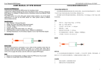
INSTRUCTION MANUAL
ECO RANGE
FAR INFRARED HEATER
Sold & Distributed in the UK & Ireland by:
Funkyheat Ltd.
The Carlile Institute
Huddersfield Road
Meltham
HD9 4AE
www.funkyheat.co.uk
This appliance complies with European Directives:
EN60335-1
EN60335-2-30
EN62233
CONTENTS
Introduction 3
Safety Instructions 4
Installation
6
Installing the thermostat receiver 7
Cleaning and Care
Disposal
8
Appendix
9
8
Introduction
In this manual there is important information for the installation of your
infrared heater. You have acquired an ecologic, economic heater and are
thereby making an effective contribution in saving the environment.
The infrared heating system proves itself through simple installation,
flexibility in the assembling and freedom from maintenance. So you can
enjoy long use of your infrared heater.
To ensure your safety, please carefully read the instructions before
installation.
Keep this manual at hand and never sell on or give this infrared heater to
anyone without the manual.
This infrared heater does not work on the principle of convection heat but
is a radiant heater. Therefore, it is possible when first switching on that
cold areas (furniture, walls, ceiling and floors) need to be warmed up first.
If you don’t immediately have a comfortable feeling of warmth, then let the
heater run for several hours, or even several days if necessary, until a
comfortable indoor climate has been reached.
As soon as the solid areas have warmed up, comfortable warmth will
spread throughout the room and then you can reduce the running time of
your heater to the minimum. The thermostat set (if supplied) will control
this for you. To enjoy the comfortable warmth to its fullest, we recommend
that you install a high-quality control (thermostat) – if you have not
purchased this already, then please contact a specialised dealer or service
company.
Safety Instructions
• The heating element must not be installed directly below a wall socket.
• The installation of an infrared heater in wet rooms (rooms with shower,
bathtub or swimming pool) as well as in public places may only be done
by a specialised installation company taking into account the
appropriate standards and norms of the country concerned.
• The infrared heater may only be connected to alternating current 230
Volt, 50Hz.
• The infrared heater must not be exposed to excessive moisture.
• Do not put objects on the infrared heater and do not cover the infrared
heater. This will cause a risk of overheating!!
• The infrared heater is equipped with a safety temperature limiting
device, which turns off the heater in case of overheating and then
automatically turns it on again after is has cooled.
• It must be possible to switch off the heater either by switch on the
socket or fused spur, or by the thermostat (if wired) at all times during
operation.
• The minimum distance to other objects should be 50cm from the front,
20cm to the sides and 10cm upward and downward.
• For the installation of an infrared heater on a brick or stone wall, only
the holding and fixing material provided should be used. On other types
of wall or masonry (e.g. plasterboard, wood) please use suitable holding
and fixing material.
• In case of possible disassembly or transport allow the infrared heater to
completely cool down before attempting to move.
• The infrared heater is not meant to be handled by persons (children
included) with reduced physical, sensorial or mental faculties or without
experience and/or knowledge, unless they are supervised by a person
responsible for their safety or receive instructions on how to use the
device.
• Children never see danger, which can occur when dealing with electrical
devices. So never leave children alone with electrical devices. Keep out
of reach of small children. If the device is installed in children’s rooms or
rooms accessible to children, make sure that the device is suspended at
a minimum of 1.2m above the ground.
• Do not try to repair the infrared heater, the power cable cannot be
replaced and must always be returned to the manufacturer for repairs. Installation Read these safety instructions and manual before use!
Check the infrared heater for visible damage and whether the main
voltage is in accordance with the voltage information on the type plate
(verso).
If you notice damage, do not install the heater – contact your specialist
dealer.
We recommend that you do not throw away the original package of the
device. Store the original package for possible transport.
Remove the existing EU plug by cutting this off, then proceed to install the
thermostat receiver, details below.
Installing the thermostat receiver
Please find below instructions for the thermostat set for your IR Heaters.
The thermostat set should only be connected by a competent person
and if you are in any doubt we recommend that this is done by a
qualified electrician. !
!
This thermostat is very advanced and will allow you to vary your
programmes for the heater throughout the day / week.!
!
The receiver needs to be connected to the power cable of the heater. !
!
!
!
1. Decide whether you want the receiver to be visible or hidden behind the
panel heater.!
!
2. Cut the power cable so that you have enough to feed through to the
receiver.!
!
3. Feed the power cable through the plastic grommet supplied with the
thermostat set and secure the grommet in place with the supplied nut.!
!
4. Connect the neutral and live wires from the heater to the connections
marked N (neutral) and L (Live) to the connectors indicated as LOAD
inside the receiver. Leave the earth cable disconnected.!
!
5. Taking the cable that you have cut off, feed the power cable through the
plastic grommet supplied with the thermostat set and secure the grommet
in place with the supplied nut. Connect the neutral and live wires to the
connections marked N (neutral) and L (Live) to the connectors indicated as
POWER inside the receiver. Leave the earth cable disconnected.!
!
6.
!
Connect the two earth wires together using an insulated connector block!
7. Replace the cover to the receiver and fix to the back of the heater if
desired. !
!
8. You now need to pair the heater. This is done automatically, but you must
ensure that the display shows a snowflake icon for this to happen. !
!
9. The wireless controller can be placed wherever in the room you feel most
appropriate and can be moved as you wish. It is sensible to try and place at
shoulder height and away from other heat sources (such as TV or
windows) since the temperature is measured by this unit and it will tell the
heater to switch on or off as required. !
The preparation of the heater can now be completed by fitting a 13amp
UK plug or hardwiring the heater to a fused spur (which must be done by a
qualified electrician).
The heater can now be paired with the wireless thermostat controller, full
details for the controller can be found in the appendix of this manual. Cleaning and Care
Before cleaning, always disconnect the main power plug.
To clean you should use a smooth and damp cloth and a little washing up
liquid detergent.
Never clean the infrared heating element and the power supply cables
under running water, nor submerse in water.
Do not use harsh, abrasive or easily inflammable detergents.
Disposal
The infrared heating element has to be disposed separately from general
household waste at municipal refuse service provided for this purpose. Y
You can obtain detailed information for disposal from your local authority.
Appendix
Sold & Distributed in the UK & Ireland by:
Funkyheat Ltd.
The Carlile Institute
Huddersfield Road
Meltham
HD9 4AE
www.funkyheat.co.uk
CC908-RF3 Wireless temperature controller
CC908-RF3 can replace most common residential thermostat and is designed to be used with
electric, gas or oil heating control system.
Unlike ordinary single unit design thermostat, this unit is a new type of thermostat separating
the thermostat function into two units. Receiver CC2010DE and Control Centre CC908-DF1. The
Receiver serves for wiring connections and heat on/off control. The Control Centre serves as user
interface and temperature sensing/control. User can put the control Centre nearby and can
read/control the temperature of really the living area while put the Receiver besides the heating
system.
SPECIFICATION
Power source ……………………….Control Centre 2 AA batteries
Receiver 220VAC±10% 50/60HZ
Frequency band………………….….868MHZ
Relay contact……………………….……16A/250VAC
Room temperature setting range………5℃-35℃(41℉-95℉)
Accuracy…………………………………..1℉or0.5℃
Dimensions……………………………Control Centre :115mm*90mm*28mm
Receiver:113mm*82mm*30mm
FEATURE
Can be placed anywhere in the home to detect and control the temperature of an area of the
user’s choice. Not limited by power control wiring locations.
Link with the Receiver via RF. Control distance 100M open site.
Large LCD display
The screen displays the set temperature and the room temperature also time simultaneously
Permanent user setting and program setting retention during power loss
Optional temperature display of Celsius or Fahrenheit scale
Both Vacation mode and hold duration mode available for comfort and energy saving
Optional programming Period: 7 individual day or Separate 5-day (weekday) and 1-day/1-day
(Saturday/Sunday) programming with 4 or 6 separate time/temperature periods per day.
Display temperature recalibrates
Low battery indication
Anti-freezing protection
Pump protection available
IMPORTANT SAFETY INFORMATION
Always turn off power at the main power source by unscrewing fuse or switching circuit
breaker to the off position before installing, removing, cleaning, or servicing this thermostat.
Read all of the information in this manual before installing this thermostat.
Only a professional contractor should install this thermostat.
All wiring must conform to local and national building and electrical codes and ordinances.
This thermostat has a removable fuse to protect the system from damage. If system is not
operating properly, check wiring and replace fuse if necessary.
Use this thermostat only as described in this manual.
1/8
Commissioning
Hold the
switch of the SAS2010DE over 3 sec,,LED of indicator lit up means for
commissioning。Hold the ④buutom of the
SAS908WHB-7-DF1 over 3 sec in standby mode, Begin
launching debug command,,Receiving part of code indicator lit up finish commissioning, Return code
value,LED of indicator lit up 4 times,;If the lights flashing said commissioning not succeed without.
Error Code
1) Low battery power alarm: When the battery power and the battery power low battery low-power
alarm,Battery alarm sign “
” blink。
2)Communication impassability alarm:When the thermostat launch stop output or start output,
Receiving no boot or not to receive signals can't return,Display section E1 flashing alarm。
E1Communication error alarm,Means to send data confiscated
E2 alarm means receiving module limited when temperature didn't answer the external temperature
probe
E3 alarm means that receive limited the temperature when no external temperature probe detection
limit temperature higher temperature than value
E4 alarm means that receive limited the temperature when no external temperature probe detection
temperature below the limit temperature value
Control centre install
1.
Remove 2 screws from the bottom of
thermostat. (See Figure 6) Gently pull the
control panel straight
off the base. Forcing or prying on the
mounting screw
thermostat will cause damage to the unit.
2.
Push power base into wall.
3.
Using two mounting screws mount the power
base
base to the wall. Place a level against bottom of
base, adjust until level, and then tighten screws.
(Leveling is for appearance only and will not
enclosure
affect thermostat operation.)
4.
Replace control panel on the power base and fix
screwed connection
power base and control panel by removed two
screws in item 1
1
Receiver install
2
P anel
B ase
R em ove the panel
3
4
2/8
Screws for mounting
thermostat to
conduit box
KEYBOARD, DISPLAY AND SWITCH DESCRIOPTION OF CONTROL CENTRE
(8) (9) (10)
(18)
(17)
(11)
(16)
(12)
(13)
(14)
(15)
①
②
③
④
⑤
⑥
Power on/ anti-freezing /off button
Time setting button
Program setting button
Program run confirmation button
Reset button
Raise Temperature setting button
⑦
⑧
⑨
⑩
Lower Temperature setting button
Shows current day or days being programmed.
Shows current time or times being programmed
Am:: Morning ,Pm:: Afternoon Days: Nr of days,Hours: Nr of hours
⑪ Shows setting temperature.
⑫ Low battery indicator
⑬ Shows temperature display in ℃ or ℉
⑭
time to get up,
morning
time to go out in the morning
time to go out in the afternoon
time to come back in the
time to return in the afternoon
time to go to bed Low battery indicator
⑮
System in Anti-freezing mode;
there is a call for heating;
System in heating mode;
Manual temperature overide operation;
Indicates a malfunction with the system;.
Vacation mode indication
⑱
Hold temperature indication
Program operation;
Program setting mode
⑯ Shows current readout temperature
⑰
Flashes when
3/8
接线图
SWITCH AND LED DESCRIPTION OF RECEIVER
Select Button
Indicator A (RED / GREEN LED)
Indicator B (GREEN LED)
Indicator C (YELLOW LED)
CHECK THERMOSTAT OPERATION
The unit will be controlled via air sensor in the Control Centre and the Control Centre will
determine to activate/deactivate heating system by comparing set temperature with room
temperature. Press ▲ to adjust Control Centre setting above room temperature 1℃ in fast
heating mode or 3℃ in slow heating mode, See configuration menu item 5. The Control Centre
will emit signals to the Receiver asking to turn on the heating device. Yellow LED on the Receiver
flashes means Receiver has received the signals. Green LED turns on means heating device is
energized. Press ▼ to adjust Control Centre setting below room temperature. The Control
Centre will emit signals to the Receiver asking to turn off the heating device. Yellow LED on the
Receiver flashes means Receiver has received the signals. Green LED turns off means heating
device is deactivated.
OPERATION
1.
Configuration Menu
The configuration menu allows you to set certain thermostat operating characteristics to
your system or personal requirements. Shortly press button ① to make sure the thermostat is in
anti-freeze mode. Hold button ③ for 3 seconds to enter the configuration menu. The display will
show the first item in the configuration menu. Press button ③ to shift to the next menu item. Use
▲ or ▼to select. To exit the menu , press button ① revert to the anti-freeze mode . Press button
④ revert to the program operation. If no buttons are pressed within 20 second the thermostat will
4/8
exit the menu. To revert to factory default setting , push ▲ or ▼ button in a same time for 3
seconds. Display will show “DEF” blinking 3 times and return to Menu item 1 indicates all the
configuration setting has reverted to factory default setting.
Step
Press buttons
Displayed(factory default) Press▲ or ▼to select
1
③
01 (0)
-3 --- +3
Select temperature display adjustment higher or lower
2
③
02 (35℃)
18℃(64℉)—35℃(95℉)
Select maximum setting temperature limitation.
3
③
03 (5℃)
5℃(41℉)—20℃(68℉)
Select minimum setting temperature limitation.
4
③
04 (℃)
℃/℉
Select temperature display to℃ or ℉
5
③
05 (FA)
FA/SL
Select fast heating or slow heating
6
③
06 (OO)
PP/OO
Select pump protection PP, Cancel pump protection OO
7
③
07 (24)
12 or 24
Selection of time scale
8
③
08 (7)
0/3/7
Programming day in one week option
9
③
09 (P6)
P4/P6
Programming period per day option
10
Press button ④ revert to the program operation
1)
Descriptions
Select temperature recalibrates Adjustment 3 LO to 3 HI –
You can adjust the room temperature display up to 3 higher or lower. Your thermostat was
accurately calibrated at the factory but you have the option to change the display temperature to
match your previous thermostat. The current or adjusted room temperature will be displayed on
the right side of the display.
2)
Select maximum temperature set point
This feature provides a maximum set point temperature f. The default setting is 35℃ (95℉),
It can be changed between 18℃ (64℉) to 35℃ (95℉).
3)
Select minimum temperature set point.
This feature provides a minimum set point temperature. The default setting is 5℃ (41℉), It
can be changed between 5℃ (41℉) to 20℃ (68℉).
4) Select ℉ or ℃ readout.
Changes the display readout to Centigrade or Fahrenheit as required.
5) Select fast heating or slow heating
Select FA to start heating immediately when the set point is 1℃ above the room temperature.
Select SL to start heating only when the set point is 3 ℃ above the room temperature.
6) Select pump protection mode
For hot water heating installation, it is recommended to activate the pump at least 15 second
every 24 hours in order to avoid any seizing. Select PP will activate pump protection mode.
Select OO will cancel the function, it shows heating out normally. When thermostat activating
15 in the display will blink..,Heating output will be automatic operated as your
the pump, ○
setting.
7) Time display
To select 12 hours or 24hours display.
8) There are 2 options for how to program the day in one week.
7: You can program in 7 individual days. Factory default is 7.
3: You can program in 5 weekday and 1Saturday and 1Sunday.
0:You can set up not programming model
9) Select separate time/temperature periods per day
P4 indicate 4 period programming per day; P6 means 6 period programming per day.
5/8
2. Manual Operation
1) On/Anti-freezing mode
You can press power button ① to activate the anti-freezing mode. The unit only displays
Clock time, Weekday and Room temperature.The default set temperature for anti-freezing mode is
5℃. During anti-freezing mode, if room temperature is below 5℃, the unit will activate the
heating system till room temperature reach to 9℃. For hot water installations, if PP had been
selected (See Configuration menu item 6), the unit will activate the pump at least 15 seconds
every 24 hours in order to avoid any seizing. Press power button ① again will terminate the
anti-freezing mode and return to normal operation mode.
2) Program operation and Hold temperature operation
Momentarily press ④ shift between program operation and hold temperature operation.
shows when thermostat is in program operation. Thermostat controls the heating system by
shows when thermostat is in
presetting program. See Planning your program section.
hold temperature operation. The thermostat will hold the room temperature at the selected
setting.
3) Temperature override
During program operation, Press ▲ or ▼ until the temperature you want is
displayed. shows in temperature override. The thermostat will override the current programming
and keep the room temperature at the selected temperature until the next program period begins.
Then the thermostat will automatically revert to the program.
4) Vacation Temperature hold
Continue pressing button ③ over 3 seconds until display will
show indicates
you have now entered into vacation hold, Use time key ② or ③ to select the number of the
days (from 1 to 99 days) during your vacation.,you can use ▲ or ▼to adjust the temperature
during your holiday. Push button ④ to revert to program operation.。To the end of vacation time,
it will automatically return to the program is running. In the vacation mode, Push button ④ to
revert to program operation.。Vacation factory set temperature is 10 ℃.
5) Reset operation
If the display is abnormal, press the Reset button by using a fine probe such as a straightened
paper clip to gently push the Rest button. This will reset the thermostat.
3. Set current day and time
1) Press ② button. The display will show the hour flashing.
2) Press and hold either ▲ or ▼ until you reach the correct hour and AM or PM designation.
(AM begins at night, PM begins at noon)
3) Press ② button once again. The display will only show minutes flashing
4) Press and hold either ▲ or ▼ until you reach the correct minutes
5) Press ② button once again. The display will show the day of the week flashing.
6) Press ▲ or ▼ until you reach the correct day of the week
Press button ④ once. The display will show the correct day of the week and the time. If no
keys are pressed within 20 seconds, the thermostat will revert to program operation.
4. Planning your program
6/8
Look at the factory preprogrammed times and temperatures shown in the sample schedule. If
this program will suit your needs, simply press the ④ button to begin running the factory preset
program. If you want to change the preprogrammed time and temperature, follow these steps.
Determine the times period and temperature for your program. You must program four periods for
each day. You can choose heating temperature and start time independently. (for example, you
may select 5:00 AM and 70℉ as the weekday 1st period heating start time and temperature and
also choose 7:00 AM and 76℉ and the weekday 1st period cooling start time and temperature)
Use the table to plan your program time periods and the temperatures you want during each period.
Fill in the complete table to have a record of your program
Heating Schedule Plan (Factory default program setting)
Wake up
6:00
21 ℃
Out
door
8:00
16.5℃
Back
home
12:00
21℃
Out
door
14:00
16.5℃
Back
home
18:00
21 ℃
Sleep
22:00
16.5℃
Enter Heating Program
1). Press ③ once. 1 (indicating Monday program) will appear in the display. Also be displayed
are the currently programmed start times for the 1st heating period and the currently programmed
temperature (flashing), icon indicates 1st program period (Get up) setting。If the display shows
1 2 3 4 5, indicating that the 5-day program will be modified, you have a 5+1+1 day model. (See
configuration menu item 8).
2). Press ▲ or ▼ to change the displayed temperature to your selected temperature for the 1st
heating program period.
3). Press ② once (the programmed time will flash). Press ▲ or ▼ until your selected time
appears. The time will change in 15-minute increments. When your selected time is displayed,
press TIME again to return to the change temperature mode.。
4). Press ③ once, icon 2nd
program period(Go out)display,the currently programmed
start time and set point temperature for the 2nd heating program period will appear
5). Repeat steps 3 and 4 to select the start time and heating temperature for the 2nd heating
program period.
6). Repeat steps 3 through 5 for the 3rd;4th;5th;6th heating program periods. If 4 period per day
selected in the configuration menu item 9, only 4 period can be programmed each day.
7). Press ③ once. “2” (indicating Tuesday program) will appear in the display, along with the
start time for the 1st heating period and the currently programmed temperature. If the display
shows 6, indicating that Saturday program will be modified in 5+1+1 day model.
8). Repeat steps 3 through 6 to complete Tuesday (7 day model) or Saturday (5+1+1 day model)
heating programming.
9). Continue entering each day’s programming until all heating periods time and temperatures
have been entered.
10). When you have completed entering your heating program, press ④.
7days program refer to above .
REVERT TO FACTORY DEFAULT PROGRAM SETTING
7/8
Press ③ button enter into program setting. Press ▲ or ▼ at the same time for 3 seconds.
Display will show DEF blinking for 3 times and back to program setting. Press the ④ button to
begin running the factory preset program. If no keys are pressed within 20 sec, the thermostat will
revert to program operation.
CHECK YOUR PROGRAMMING
Follow these steps to check your thermostat programming one final time before beginning
thermostat operation.
1. Press button ③ to view the 1st weekday heating period time and temperature. Each time you
press button ③, the next heating period time and temperature will be displayed in sequence
for weekday, then Saturday and Sunday program periods (you may change any time or
temperature during this procedure).
2. Press button ④ to begin program operation.
CUSTOMER ASSISTANCE
After reading this guide, if you have any question about the operation of your thermostat, please
contact your installer or service provider.
8/8