1
SCIMPI
(Simple Instrument for Measuring Parameters In Situ)
User Manual
version 1.0
Transcendev
Woods Hole
Marine Systems, Inc.
Acknowledgement: SCIMPI was developed for the Integrated Ocean Drilling Program
Management International (IODP-MI) under the sponsorship of the U.S. National
Science Foundation.
Table of Contents
Handling and Storage Precautions .................................................................................................. 3 Overview .................................................................................................................................................. 4 Anatomy of a SCIMPI String...................................................................................................................................4 Anatomy of a SCIMPI Measurement Module ..................................................................................................6 Measurement Supervisor ............................................................................................................................. 7 Anatomy of a SCIMPI Command Module..........................................................................................................8 Master Controller............................................................................................................................................. 8 SCIMPI Communication, Control, and Power Architecture......................................................................9 SCIMPI Physical Block Diagram.............................................................................................................. 11 SCIMPI Sensors.....................................................................................................................................12 Temperature Sensor ...............................................................................................................................................12 Pressure Sensor.........................................................................................................................................................12 Electrical Resistivity Sensor ................................................................................................................................12 Temperature Effects .................................................................................................................................... 12 Sensor Calibration ...................................................................................................................................................13 Power Requirements .........................................................................................................................14 Power Management ..................................................................................................................................... 14 Internal Battery Packs ................................................................................................................................ 14 Serial Communications .....................................................................................................................15 Configuring SCIMPI .............................................................................................................................16 Editing Instruction Sets.............................................................................................................................. 17 Deployment ...........................................................................................................................................19 Pre-Deployment Preparation .............................................................................................................................19 SCIMPI Deployment Procedure..........................................................................................................................19 Power and Communications During Deployment .....................................................................................20 Appendix A ............................................................................................................................................22 SCIMPI Internal Wiring Key ................................................................................................................................22 Appendix B ............................................................................................................................................23 SCIMPI Interface to ERS and MFTM ................................................................................................................23 SCIMPI User Manual, version 1.0
Page 2 of 25
Handling and Storage Precautions
Do not allow anything electrically conductive to come in contact with pin 1 of the Seacon
Metal Shell Series (MSS-L) connector at either end of a SCIMPI Measurement Module.
Pin 1 is identifiable by its alignment with a mechanical keyway on the inside surface of
the connector barrel. SCIMPI modules that contain internal battery packs provide live
voltage (+14.4 VDC) to pin 1. Shorting this pin to any other connector pin or with
anything on the stainless steel surface of the pressure housing, including the electrical
resistivity sensor contacts, can result in damage to the internal electronics as well as
possible fire or explosion hazard.
If it is discovered that pin 1 of any
module has been electrically shorted to
any other conductive surface on the
module for long enough to significantly
discharge the internal battery, caution
should
be
exercised
when
disassembling the module because high
pressure or toxic gases may have built
up inside as a result of rapid battery
discharge.
SCIMPI User Manual, version 1.0
Page 3 of 25
Overview
The acronym SCIMPI stands for Simple Cabled Instrument for Measuring Parameters In
situ. SCIMPI is a permanently emplaced borehole monitoring system for unconsolidated
sediment that provides a relatively inexpensive alternative to straddle-packer based
systems. Emplaced in the seafloor via drill ship, the modular SCIMPI system provides
flexibility in both the number of modules and the spacing between them. It can be
connected to cabled observatory infrastructures or powered by internal batteries and
serviced via ROV to retrieve logged data.
SCIMPI is designed for hydrogeological conditions in which the borehole will collapse
around the device once the drill string through which it is emplaced is withdrawn.
Borehole relaxation occurs because of two different processes: slower, creep-dominated
deformation in fine-grained clays and shales and immediate collapse in uncemented
coarse-dominated sediments.
A SCIMPI string consists of multiple Measurement Modules and a Command Module
connected by varying lengths of cable. It is powered and controlled via wet-mateable
connection to either a ROV-replaceable Command Module or to cabled observatory
infrastructure. The physical arrangement of modules is serial, but the two-wire RS-485
communications and 12-48 VDC power interfaces are bus-oriented.
SCIMPI is modular at multiple levels of the system hierarchy. At the highest level, a
SCIMPI's modular design enables sensor emplacement at custom depth intervals, to
intersect and monitor any stratigraphic horizons the user chooses to target.
SCIMPI is deployable through an IODP drill string directly into the borehole without reentry or a ROV. Thus, no re-entry cone, casing hangers, or other heavy borehole
infrastructure is required. Eventual borehole collapse provides intimate contact between
SCIMPI and the formation. SCIMPI is therefore suitable only in sediments in which an
unlined borehole will eventually collapse. SCIMPI can be powered via either connection
to cabled observatory infrastructure or from modular internal battery packs. When not
connected to a cabled observatory, data are retrieved and power supply is replenished via
ROV.
SCIMPI was developed with funding from IODP-MI by a team led by University of
Rhode Island Graduate School of Oceanography (URI-GSO) and which included
Transcendev, Woods Hole Marine Systems, Inc., Stress Engineering, and LamontDoherty Earth Observatory.
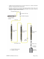
Anatomy of a SCIMPI String
From the bottom up, a SCIMPI string typically consists of:
o
A 500-lb ballast weight to maintain cable tension and provide a sensible decrease
in tension to the deployment winch operator when target depth is reached.
o
A length of structural cable between the ballast weight and the bottom
measurement module.
o
Any number of Measurement Modules with Intervening Buoyant Cable and
syntactic foam floats attached to the cable.
o
A topmost length of Bouyant Cable with an integral ROV-serviceable wet-mate
connector
SCIMPI User Manual, version 1.0
Page 4 of 25
o
Additional cable extending from the wet-mate connector to a seafloor Command
Module or cabled observatory infrastructure
o
Buoyancy provided by the syntactic foam beads maintains cable tension and
keeps the wet-mate connector and Command Module above seafloor while the
drill pipe is “stripped” from the borehole.
SCIMPI User Manual, version 1.0
Page 5 of 25
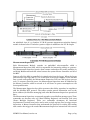
Anatomy of a SCIMPI Measurement Module
Measurement Modules and Command Modules are themselves modular and, in addition
to including sensors, can include battery packs connected in parallel to the DC power bus
in any number and combination. Pressure housings for SCIMPI modules can be
constructed modularly and all consist of a small number of distinct parts that are
interchangeable. These include tubes, end caps, and couplers that are either passive or
instrumented. Most Measurement Modules have two chambers (one for batteries and
another for sensors), consisting of two tubes, an instrumented coupler (providing for
sensor contact with the environment), and two end caps (with connectors for intramodule cabling). The first SCIMPI pressure housing components were made of 17-4 PH
stainless steel, hardened to condition H1025. However, they can be made of alternate
materials (titanium, etc.) depending on site and deployment requirements.
Cutaway views of a P-T-R (Pressure-Temperature-Resistivity) Measurement Module and
a T-R-B (Temperature-Resistivity-Battery) Measurement Module are shown below. Both
use substantially the same 2-chamber housing configuration, except that the T-R-B
module uses a temperature-resistivity coupler that differs from the P-T-R coupler by the
absence of a pressure sensing port.
SCIMPI User Manual, version 1.0
Page 6 of 25
An unlabeled view of a 3-chamber P-T-R-B (pressure-temperature-resistivity-battery)
module is shown below. It includes a passive coupler in addition to the P-T-R coupler.
Measurement Supervisor
Each Measurement Module contains an embedded microcontroller called a
Measurement Supervisor (MS), which is responsible for interacting with up to 4 sensors.
The Measurement Supervisor queries these sensors and makes the results available via
an RS485 Modbus network that exists between the system Master Controller and all of
the MSs.
Power to all of the MSs is controlled via a single wire from the logger. When the logger
pulls this line logic high (Bus V+) via a GPIO, all of the power supplies on the bus will
turn on and consequently the Measurement Supervisor will boot and begin to process
code. To conserve electrical power, the Measurement Supervisor must be addressed by
the Master Controller within 2 seconds or it will lower its power consumption to the
lowest possible state.
The Measurement Supervisor has table structures that define operation in compliance
with the ModBus RTU protocol. The tables contain general information such as the
device address (for Modbus messaging) and other Measurement Supervisor operational
data.
The Measurement Supervisor accepts and responds to two Modbus message types. These
commands are function code 0x3 (Read Holding Registers) and function code 0x10
(Preset Multiple Registers). These two commands encompass all functional
requirements. Function 0x10 can be used to write a single register, used to trigger sensor
interaction. A Master Controller that understands the protocol for writing and reading
table entries that trigger the needed Measurement Supervisor interactions with sensors
SCIMPI User Manual, version 1.0
Page 7 of 25
and report results must be used to acquire data. The Master Controller may be physically
contained within a Measurement Module but typically is in a separate Command
Module, as described below.
Anatomy of a SCIMPI Command Module
The SCIMPI Command Module is the ROV service-cable component that lies on the
seafloor when SCIMPI is deployed in a borehole. It always contains a SCIMPI Master
Controller. To log data from a SCIMPI that is not connected to cabled observatory
infrastructure the embedded Master Controller is always required. When placed in-line
with a cabled SCIMPI deployment, the Master Controller provides an easy way to acquire
data from SCIMPI's Measurement Modules and provide an ASCII-formatted stream to
the cabled observatory via RS-485 serial communication. A see-through view of a basic
Command Module is shown below. The Command Module can optionally contain one or
more battery packs and/or a Measurement Supervisor board as well as sensors in
additional chambers using modular SCIMPI pressure housing parts. Multi-chamber
SCIMPI modules are shown in the Anatomy of a SCIMPI Measurement Module section
of this manual.
Master Controller
The Master Controller is the main processing and data storage component in the SCIMPI
system. It consists of a Datalogger based on the GHI EMX single board computer module
with 72Mhz processor running Microsoft Micro Framework and a Supervisor based on a
TI MSP430. The operational schedule for the Datalogger is mainly controlled by the
Supervisor. The Supervisor is responsible for waking and shutting down the Datalogger.
The Datalogger is responsible for telling the Supervisor when it is to be shut down,
specifically when it has completed an acquisition and logging cycle. The Datalogger is
SCIMPI User Manual, version 1.0
Page 8 of 25
also responsible for sending data to the surface during deployment, communication with
all Measurement Supervisors, communication with the Supervisor, and managing data
for the entire system.
Upon boot the Datalogger determines the state of the deployment signal. If in
deployment mode (connected to external power through the Command Module's upline
interface) the Datalogger will continuously poll all of the sensors on the bus and relay
that information in ASCII format to the upline RS-485 serial bus connected to a drill ship
or cabled observatory.
If the deployment line is low, the logger will wake the SCIMPI power bus and begin
executing the user-defined Instruction Set. When the logger is done querying it writes
the next sleep duration to the Supervisor and initiates the next sleep cycle.
SCIMPI Communication, Control, and Power Architecture
The SCIMPI logical architecture of Measurement and Command Modules is highly
modular to maximize flexibility in the physical configuration and combination of
modules, and minimize overall power consumption by optimizing the pattern of
components that must be powered on at any given time. The modularization also renders
the architecture highly scalable and distributable, to support future additional
measurement functions, single-module datalogging, and tight integration with the
emerging architecture of the Ocean Observatories Initiative (OOI) Cyber Infrastructure
(CI).
Whether embodied in several Measurement Modules under the control of a single
Command Module, or as is a stand-alone single-module with embedded master
controller/datalogger, the SCIMPI architecture includes functional units for the
following logical processes:
1. Smart Sensor Controller (SSC) – component of a smart sensor that makes a
transducer it "smart." Typically a SSC interfaces to the sensor transducer
circuitry, controls electrical excitation of the transducer, performs digital-toanalog conversion of the transducer output, maintains and applies calibration
coefficients or other metadata necessary to convert transduction output to
relevant physical units, and handles communication with a host via a defined
serial messaging protocol. Each smart sensor is composed of a transduction
mechanism paired with to a SSC. A SCIMPI will include three discrete SSCs. They
are communicated with via serial ASCII over an internal RS-485 bus confined
within each Measurement Module.
2. Measurement Supervisor – aggregates the logical functions of three or more
third party smart sensors, each with its own power requirements and serial
messaging protocol, into a single logical address and messaging protocol
(message normalization), controls power individually to the smart sensors,
communicates individually with the smart sensors and with a single master
(either a Master Controller process or PC application).
3. Master Controller – controls one or more Measurement Supervisors, determines
the wake/sleep status of all Measurement Supervisors at once, remembers the
addresses of and communicates with multiple Measurement Supervisor to
acquire measurements, and reads and writes entries in the Modbus tables of the
Measurement Supervisor via the external RS-485 serial data bus. The Master
Controller is capable of acquiring, time-stamping, and logging data from the MSs
on a programmable schedule. The Master Controller includes a real-time clock,
implements an ultra low power sleep mode, and include removable media storage
to both manage overall SCIMPI energy consumption and function as a
SCIMPI User Manual, version 1.0
Page 9 of 25
programmable datalogger. The Master Controller's functions are divided between
a Microsoft .NET Micro Framework (.NET MF) single-board computer and a TI
MSP430 ultra low power microcontroller. The .NET MF Datalogger implements
the datalogging and external communications functions, and shuts down entirely
between measurement cycles, informing the MSP430 Supervisor of its next
waking time and state. The MSP430 acts as an alarm clock for switching on
power to the .NET MF datalogger, and informs the datalogger of its (post-boot)
waking state when asked. In a Regional Cabled Observatory (RCO) deployment
scenario, the resources and process represented by a SCIMPI Master Controller
may be embodied in a RCO Data Acquisition node.
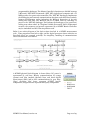
Below is an activity diagram of the basic actions involved in a SCIMPI measurement
cycle. Time progresses from left to right, and the logical processes whose activities are
described above are arranged vertically. For simplicity, handling of communications
errors and timeouts is not shown.
A SCIMPI physical block diagram is shown below. DC power is
represented by red lines, RS-485 communications by orange
(system) and blue (module internal) lines, and direct digital
input/output (DIO) and/or SPI communications by gray lines.
Large, enclosing blue boxes represent SCIMPI specific
components, and green boxes represent third party components.
SCIMPI User Manual, version 1.0
Page 10 of 25
SCIMPI Physical Block Diagram
There is a one-to-one correspondence between a Measurement Supervisor process and a
physical Measurement Module. Each Measurement Module appears to a Master
Controller process as a single Measurement Supervisor having a single logical address.
All MSs utilize the same messaging protocol. A Master Controller can be embedded in a
Command Module as described in the Anatomy of a SCIMPI Command Module section
of this manual, or the SCIMPI Config Windows desktop application can serve as a Master
Controller.
SCIMPI User Manual, version 1.0
Page 11 of 25
SCIMPI Sensors
Temperature Sensor
SCIMPI Measurement Modules that are equipped for temperature, integrate a modified
SBE-38
precision
oceanographic
thermometer
from
Seabird
Electronics
(www.seabird.com). The stock Sea-Bird pressure housing has been discarded to mount
the thermometer in the SCIMPI module. This process requires unsoldering the
thermometer leads from the unit's electronics and re-soldering the connections after
mounting the thermometer in a SCIMPI part. No other modifications are made.
The SBE-38 has a range of -5 to +35 ºC. Users are referred to the SBE-38 Users Manual
for more detailed information on operation of the SBE-38.
Pressure Sensor
SCIMPI Measurement Modules that are equipped for pressure, integrate a Paroscientific
410K-101 DigiquartzTM transducer and a 1764-001 Intelligent Interface card by default
(www.paroscientific.com). The 410K-101 has a range of 0-10000psi. Digiquartz
transducers in other pressure ranges are also available at the time of new system
specification.
Users are referred to the Paroscientific user documentation for more detailed
information on operation of the pressure sensing subsystem.
Electrical Resistivity Sensor
SCIMPI Measurement Modules that are equipped for electrical resistivity integrate a
Transcendev ERSS (Electrical Resistivity Smart Sensor) (www.transcendev.com). The
ERSS is a compact, low power smart sensor that acquires readings from any 4-electrode
galvanically coupled (Wenner-style) array supplied by the integrator. A user configurable
parameter stored in ERSS memory accounts for the electrode geometry. In SCIMPI, the
electrodes are 0.25 in (10mm) in diameter and separated by 0.75 in (30mm).
ERSS in SCIMPI is configured for a default measurement range of 0.1-100 ohm-m and to
alternate the polarity of the signal applied to the outer electrodes at a rate of 100 Hz.
Other configurations are available at time of SCIMPI system specification. Users are
referred to the ERSS Users Manual for more detailed information on configuration,
calibration, and operation of the ERSS.
Temperature Effects
The electrical conductivity (inverse of resistivity) of seawater and other materials,
including marine sediments, varies with temperature. The chart below shows the
magnitude of the temperature effect for seawater.
SCIMPI User Manual, version 1.0
Page 12 of 25
The ERSS measures and reports resistivity at the prevailing ambient temperature, which
should be independently ascertained if the user desired to compute a temperature
compensated resistivity value. The ERSS does not provide on-board temperature
compensation because the relationship of resistivity to temperature varies as a function
of the medium. Since the ERSS does not know what medium it is deployed in, it is up to
the user to perform temperature corrections of the reported electrical resistivity for the
given medium.
Sensor Calibration
All sensors in SCIMPI are factory calibrated by the individual sensor manufacturers.
SCIMPI User Manual, version 1.0
Page 13 of 25
Power Requirements
SCIMPI Measurement Modules are powered by connection to the common DC power
bus, which may be fed by any battery pack present inside any connected module. All
measurement modules are simultaneously signaled to power up and power down via a
DC signal voltage on a separate power conductor as needed to acquire measurements.
Power-up occurs gracefully in response to changes in signal state. Modules will handle
input voltages from 9 to 48 volts.
Power Management
SCIMPI power management is fairly straightforward yet highly efficient. When a reading
is desired, a voltage controlled wake signal from the Command Module activates a power
latching circuit embedded in each Measurement Module. This provides power to boot
the Texas Instruments MSP430 ultra-low power microcontroller embedded in each
Measurement Module that executes the functions of a logical process known as the
Measurement Supervisor. The Measurement Supervisor monitors the RS-485
communications bus for data requests and responds accordingly. The Master Controller
process running on the datalogger itself shuts down between measurement events,
leaving on only a real-time clock (which is button cell battery backed for shelf life) and an
ultra low power MSP430 that acts as a supervisor to keep time between acquisition
intervals and wake the datalogger as needed.
Internal Battery Packs
Each T-R-B or P-T-R-B module contains one internal battery pack. P-T-R modules do
not contain batteries. ("B" in the module designation stands for "battery".) Each original
equipment battery pack comprises 12 C-sized primary lithium thionyl chloride cells in 3
parallel stacks of 4 cells in series to provide 26 amp hours at 14.4 volts DC (nominal).
The batteries are not rechargeable.
If SCIMPI modules are stored for more than one year, their internal battery packs should
be replaced or, at a minimum, thoroughly tested prior to deployment. Replacement
battery packs can be obtained from Transcendev (www.transcendev.com), or from any
custom battery pack manufacturer from which cell chemistries with sufficient energy
density are available.
SCIMPI User Manual, version 1.0
Page 14 of 25
Serial Communications
Serial communications between Measurement and Command Modules (or between
Measurement Supervisors and a Master Controller) utilize a Modbus RTU compliant
protocol over a RS-485 two-wire bus at 9600 baud, no parity, with one stop bit. The
Modbus protocol is visible in the sensor data monitoring window of the SCIMPI Config
Windows desktop application.
SCIMPI User Manual, version 1.0
Page 15 of 25
Configuring SCIMPI
SCIMPI is configured via a Windows personal computer application called SCIMPI
Config that is compatible with Windows XP, Vista, and Windows 7.
SCIMPI Config enables the user to develop and test Master Controller Instruction Sets
that are executed each time the Master Controller wakes to acquire data from a SCIMPI
string. These Instruction Sets can be stored on the computer's hard drive or other media
and downloaded to a SCIMPI Master Controller via serial interface to the computer.
Instructions sets can also be fed to the Master Controller by saving or transferring to a
Secure Digital (SD) memory card and inserted into the Master Controller's SD card slot.
Four types of instructions can be included in Instruction Sets or executed individually
against serially connected modules from within SCIMPI Config. An addressed
measurement module can be instructed to:
o
Turn power on or off to individual sensors within a module,
o
Issue a serial command to an individual sensor,
o
Acquire and parse a serial response string from an individual sensor, and
o
Wait a specified number of milliseconds before executing the next of the other
three instruction types.
Each execution of an Instruction Set results in the PC or Datalogger generating one
timestamped serial ASCII record in the data log. This record contains the system
timestamp in coordinated universal time (UTC) followed by the parsed responses from
all sensors read in the order in which they were read.
SCIMPI Config also allows the user to assign a logical address to a singularly connected
Measurement Module via serial communication, to specify the time that the Datalogger
sleeps between each execution of its Instruction Set in situ, and to specify the time
between executions of the Instruction Set when the Master Controller is receiving power
from a source external to the SCIMPI string through the IE4-BC connector on the
Command Module.
SCIMPI Config also provides several troubleshooting capabilities, including:
o
Reporting when a Measurement Module has not responded in a reasonable
amount of time.
o
Reporting when an illegitimate communication has been received from a
Measurement Module.
o
Recording a session log of all communications between the SCIMPI Config
program and a string of Measurement Modules.
Below is a screen shot showing the major components of the SCIMPI Config user
interface. The program setup toolbar is at the top of the screen and allows the user to
choose the COM ports to which the Master Controller (in Command Module) and/or
Measurement Supervisors (in Measurement Modules) are attached, set a Measurement
Module address, set the Datalogger (Master Controller) real-time clock to the computer's
system time, and set the sampling period (time between wake cycles) of the Datalogger
when it is in in situ mode (not powered from the upline interface).
Note: When connecting to a datalogger, a serial port (RS-485 interface) on
the PC must be connected to the Datalogger's upline interface. A separate
SCIMPI User Manual, version 1.0
Page 16 of 25
serial port is used to connect to Measurement Modules. Do not connect a
Datalogger to the same RS-485 bus as a PC and Measurement Modules since
data collisions will result from there being two Master Controllers (the
Datalogger and the PC) on the bus.
The activity-monitoring panel on the right half of the screen has several tabs that can be
selected to view the activity being written to various log files on the hard drive. The
application log contains information about execution of the SCIMPI Config program,
error codes, etc. The data log is a time stamped, comma separated list of parsed sensor
responses that is identical to the file that will be recorded by the Datalogger in the field
and the ASCII data stream echoed to the upline RS-485 bus during deployment. The
logger stream shows data being streamed from any connected Datalogger (Master
Controller) in deployment mode. And the sensor transport log shows the actual Modbus
traffic between the PC and any connected Measurement Modules.
Editing Instruction Sets
The Instruction Set Editor occupies the left half of the screen and includes at the top the
Instruction Set Editor Toolbar shown below.
The functions of the various buttons in the Instruction Set Editor Toolbar, from left to
right, are:
1. Load a saved Instruction Set
2. Create a new Instruction Set
3. Add a sensor power control instruction
4. Add a time delay instruction
SCIMPI User Manual, version 1.0
Page 17 of 25
5. Add a write to sensor instruction
6. Add a read from sensor instruction
7. Add a logger test instruction
8. Delete the highlighted instruction
9. Save the current Instruction Set to disk
10. Run the current Instruction Set
11. Download the current Instruction Set to a connected Datalogger
The name of the Instruction Set can be entered into the box below the Instruction Set
Editor Toolbar and will be the default name of the file when the Instruction Set is saved
to disk.
A user creates Instruction Sets by inserting instructions in the order in which they are to
be executed by the Datalogger.
Each instruction inserted displays user-editable fields for addressing the module to
which the instruction applies, checking sensors that are to be activated, entering serial
communications strings in the language of the individual sensor, etc. Sensor reading
instructions allow the user to select which bytes in the sensor's ASCII response to write
to the data log.
The order of instructions can be changed by clicking and dragging on the dimpled
pattern at the left side of each instruction, and instructions can be tested individually by
clicking the green triangle to the right of the user-editable description.
Once Instructions Sets have been created and tested against a collection of connected
Measurement Modules, they can be either uploaded to a connected datalogger where
they will be written to the datalogger's SD card as the default Instruction Set file to
execute during in situ logging, or saved to disk for later recall or direct transfer to a SD
card to be inserted into a datalogger thereby provide it the instruction set.
SCIMPI User Manual, version 1.0
Page 18 of 25
Deployment
SCIMPI is designed to be deployed into a borehole from the drill ship JOIDES
Resolution (JR). SCIMPI will be emplaced in an unlined borehole created by the JR, by
lowering it through the drill string while the JR remains on station. Instrument function
in situ is verified via communication through the JR’s Schlumberger wireline umbilical
prior to releasing the tool, recovering drill pipe, and vacating the station. Design
innovations have allowed for a small enough Command Module to deploy through the
drill pipe by distributing small battery packs in parallel throughout SCIMPI’s downhole
Measurement Modules rather than in a single pressure housing on the seafloor. Thus the
slim, attached Command Module can accompany the Measurement Modules through the
drill string during initial deployment, obviating the need for an ROV and crew on the
deployment cruise. The concept of operations is detailed below as sequences of steps
required for pre-deployment preparation and deployment (while on station).
Pre-Deployment Preparation
1. Verify proper function of SCIMPI sensors and communications using fully
assembled string prior to cruise,
2. Ship disassembled system to IODP port of call,
3. Receive and load unassembled SCIMPI onto drill ship (JR),
4. Conduct shipboard functional testing of SCIMPI modules en route to drilling
destination (optionally assembling/testing/disassembling system on deck if
schedule allows),
5. Stage SCIMPI components and deployment equipment on deck (before or during
drilling),
6. Deploy according to the procedure below.
SCIMPI Deployment Procedure
1. Drill borehole to target depth (use of drilling mud to keep borehole open is
discretionary) using a bit of diameter 9-7/8”
2. Optionally deploy re-entry cone
3. Drop bit downhole
4. Assemble SCIMPI sections on deck
5. Assemble SCIMPI on deck while feeding completed sections into the top of the
drill string, hanging alternately from makeup plate and overhead rigging as
assembly progresses
a. SCIMPI will hang in the makeup plate while each new grip on the cable is
established
b. Repeat until full SCIMPI string hangs from makeup plate, with command
module at top
6. Mate assembled MFTM and ERS overshot to pulling neck of SCIMPI command
module, hanging in Schlumberger makeup plate. MFTM and ERS will be
connected to 26,000-ft spooled armored Schlumberger wireline logging cable.
SCIMPI User Manual, version 1.0
Page 19 of 25
7. Test communications through wireline cable with all measurement modules in
fully assembled string
8. Lower SCIMPI through drill pipe to target depth, sensing TD attainment via
combination of wireline spool metering and tension spool
9. Verify communications through wireline cable with all measurement modules in
fully assembled string
10. Activate the SCIMPI release tool in the ERS (use DC current from shipboard to
drive the DC release motor)
11. Withdraw wireline cable
12. Strip drill pipe. After this point, the SCIMPI seafloor tether should be free
floating from the wellhead or, optionally – if the inline battery arrangement is
used – the Command Module should be attached and either free floating
(pending the syntactic foam distribution) or lying on the seabed.
13. Vacate Station
Power and Communications During Deployment
When not connected to cabled observatory infrastructure, SCIMPI utilizes battery packs
distributed throughout its Measurement Modules (or in a Command Module) for power.
This power is carefully conserved to last for deployment periods on the order of years.
SCIMPI therefore receives its power during deployment (when it is necessary to
frequently monitor SCIMPI's operational status) from the surface vessel via the wireline
umbilical to which it is tethered. SCIMPI automatically switches between a frequent
measurement and reporting mode and an infrequent measurement and recording mode
on the basis of whether or not power is present at the IE4-BC connector on the command
module. The sequence of physical events and corresponding SCIMPI mode and condition
changes are as follows:
o
The SCIMPI Measurement Modules will begin in a non-operating state. The
measurement modules will not operate except when signaled to wake via voltage
on the wake signal conductor of the downline interface. The battery packs within
them, however, still supply power to the power bus.
o
The Master Controller hosted within the SCIMPI Command Module will begin in
a deep sleep state in in situ mode, recording and non-echoing condition. Its
internal ultra low power supervisory microcontroller will be powered by an
internal lithium button cell, and will be executing the in situ mode
sleep/acquisition schedule. However, prior to awakening the internal .NET MF
system that hosts the Master Controller process, if the command module is no
connected to any outside power supply, the supervisor will sense the voltage level
of the internal power bus and, finding insufficient voltage on the bus, will not
wake the .NET MF system and will instead enter another sleep interval.
o
When the chain of SCIMPI Measurement Modules is assembled and suspended
in the drill string from the Schlumberger C-plate, there is no load on the
distributed battery power supply because no Datalogger is connected and
instructing the Measurement Modules to wake.
o
The SCIMPI Command Module will be the last module connected to the string; it
is attached above the Measurement Modules via a Seacon MSSL connector, with
a wet-mate connector in line between it and the rest of the string. At this time,
SCIMPI User Manual, version 1.0
Page 20 of 25
the Command Module and internally hosted Master Controller process will
power up from the battery power supply connected to the downline electrical
interface and, sensing no supplied power at the upline electrical interface (e.g.,
the IE4-BC connector in the pulling neck), will enter in situ mode, in which it
infrequently boot up, signal the connected Measurement Modules to wake,
acquire a round of measurements, then re-enter a deep sleep condition.
o
With the SCIMPI Command Module hanging in the C-plate, the ERS/MFTM will
be attached to the SCIMPI pulling neck and upline electrical interface. This action
will make electrical connection between the MFTM and SCIMPI, after which
12VDC power to SCIMPI’s upline electrical interface will be switched on from the
MFTM. This power will cause the Command Module’s upline interface isolation
circuit to complete the power and communications circuits with the SCIMPI
Master Controller host, which will awaken the Master Controller from its deepsleep condition. The Master Controller will sense the presence of power supplied
at the upline interface and will execute frequent measurement and reporting
using power supplied to the upline interface which it also provides to the internal
power bus to power the Measurement Modules at higher voltage than the
internal battery packs to prevent them from discharging.
o
The entire SCIMPI and ERS/MFTM are then lowered down the drill string on the
Sclumberger wireline umbilical, during which time power to the SCIMPI from
MFTM remains on and SCIMPI remains in frequent measurement and reporting
mode, taking measurements at intervals of 2 to 10 seconds and echoing them to
surface diagnostic equipment via the upline interface and MFTM. During this
time, the Master Controller will also continually sense the power supplied to the
Command Module’s upline interface, and if an insufficient power condition is
sensed it will switch to infrequent measurement and recording. If power is again
restored, it will wake the Master Controller into frequent measurement and
reporting mode.
o
When target depth is achieved and a drop in cable tension is sensed by the
MFTM, the MFTM will be commanded from the surface to switch off power being
supplied to the SCIMPI via the command module upline interface. This action,
necessary to avoid exposing powered conductors to seawater upon release of the
SCIMPI, will cause the SCIMPI Command Module and internally hosted Master
Controller to switch to infrequent measurement and recording. The loss of power
at the upline interface will open the upline interface isolation circuit and sever
electrical contact between the upline interface and the Datalogger and
measurement modules.
o
Power will be delivered to the ERS motor through the umbilical from the surface
to actuate the release mechanism, and SCIMPI will separate from the ERS,
unplugging the now inactive IE4 connector.
o
ERS/MFTM will be retrieved and drill pipe will be stripped, leaving SCIMPI in
situ until serviced by an ROV.
SCIMPI User Manual, version 1.0
Page 21 of 25
Appendix A
SCIMPI Internal Wiring Key
Resistivity Leads
(26 AWG stranded copper)
Molex C-Grid Connector Pin
SL 70066/70634
Excitation+: Orange (toward battery/pressure end)
1
Sense+: Purple
2
Sense-: Brown
3
Excitation-: Gray (toward temperature/Measurement Supervisor end)
4
Sensor Bus (module internal)
Hirose DF3 Connector Pin
+V (Power): Red 22 AWG stranded
1
Common: Black 22 AWG stranded (U11/U22)
2
RS-485 + (A): White 24 AWG stranded
3
RS-485 - (B): Green 24 AWG stranded
4
Power Bus
Seaconn MSSL Connector Pin
+V (Power): Red 22 AWG stranded (U6/U18)
1
Return (Common): Black 22 AWG stranded (U11/U22)
2
+V Wake: Green/yellow 24 AWG stranded (U10/U21)
3
RS-485 (24 AWG, 3 twists per inch)
Seaconn MSSL Connector Pin
+(A) White (U9/U20)
4
-(B) Green (U7/U19)
5
Command Module Up-hole End
Impulse IE-4-BC Connector Pin
+V (Power): Red 22 AWG stranded
2 (White)
Return (Common): Black 22 AWG stranded
4 (Green)
RS-485 + (A): White 24 AWG stranded
1 (Black)
RS-485 - (B): Green 24 AWG stranded
3 (Red)
SCIMPI User Manual, version 1.0
Page 22 of 25
Appendix B
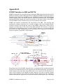
SCIMPI Interface to ERS and MFTM
SCIMPI is deployed into a borehole using a customized ERS release mechanism from the
IODP tool inventory below a Multi-Function Tool Module (MFTM) developed by Lamont
Dougherty Earth Observatory (LDEO) on the JIODES Resolution's (JR) Schlumberger
wireline logging string. The MFTM mediates shipboard communications with SCIMPI
through the wireline system and controls activation of a DC electric motor in the ERS to
release SCIMPI from the wireline string once into position in the borehole.
SCIMPI will interface mechanically and electrically to the ERS. The electrical and
mechanical coupling components are co-axially arranged, with a male Impulse IE4-BC
electrical connector up through the center of the SCIMPI “pulling neck” (male) that is
engaged by locking dogs in the barrel of the ERS (female). The interface is depicted
conceptually in the drawings below. A female IE4-BC connector is recessed within the
lower end of the ERS. Dimensions shown are notional. The wiring key for the IE4-BC
connector appears in Appendix of this manual.
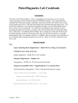
The pulling neck of the SCIMPI, depicted below, is cylindrical with a mushroom shaped
head and a circumferential groove for engaging with the ERS locking dogs. It includes an
axially aligned notch that must align with a pin on the interior of the ERS barrel to
assure correct mating of the Impulse IE4-BC connector pair and to prevent random
torque being applied to the electrical connector during deployment. The orientation
reference direction for alignment is based on the IE4-BC connector guide pin. The design
SCIMPI User Manual, version 1.0
Page 23 of 25
of the SCIMPI pulling neck assembly allows the user to control alignment of the IE4-BC
pins with the slot in the next to match the mating ERS. The IE4-BC is threaded into a
cylindrical cartridge that is inserted into the top of the pulling neck and held in place by a
retaining nut. This allows the user to control alignment of the IE-4 pin pattern relative to
the slot in the pulling neck that controls alignment between SCIMPI and the ERS. Slots
in the cartridge provide access to the hex flange on the IE4-BC so that is can be tightened
into place. The right hand drawing is a cutaway of the left hand drawing revealing the
form of the cartridge and retainer nut. The cartridge includes both face and bore seals to
ensure integrity of the command module pressure housing.
The SCIMPI pulling neck is ordinarily made of 17-4 PH stainless steel, hardened to
condition H1025. Like other housing components, the neck can be made of alternate
materials (titanium, etc.) depending on site and deployment requirements.
The Impulse IE4 is a two-pin, 4-conductor wet connector. The bulkhead IE4 connector
on the SCIMPI housing is male, as the female connector of this model is not open-face
pressure qualified. This requires the in-line connector on the ERS to be female, which is
a reversal of the usual convention for exposed live conductors in a submerged marine
environment. The SCIMPI command module automatically severs its electrical
connection to the exposed male IE4 once it loses power from the ERS. This is
accomplished by the use of a photo-coupled solid state relay (SSR) so there are no
moving parts. Mating the SCIMPI to the ERS provides power through the IE4-BC that
will is conditioned within the command module to provide a low voltage signal to the
internal LED of the SSR. This LED activates an internal photo-sensitive diode connected
to the gate of a MOSFET (metal–oxide–semiconductor field-effect transistor) that
connects the main power conditioning circuit to the ERS-supplied power. It performs a
DC-to-DC conversion that keeps the output voltage on the SCIMPI unswitched power
bus above the nominal internal battery pack voltage so that all current comes from the
ERS rather than the batteries whenever SCIMPI is powered from the ERS. The MFTM
and ERS are powered through the 7-conductor Schlumberger wireline cable and 31-pin
connector. DC power at 12 or 24 volts is provided to SCIMPI from the MFTM, through
SCIMPI User Manual, version 1.0
Page 24 of 25
the ERS. The SCIMPI command module can accept DC power from 9 to 40 volts through
the IE4-BC and draws less than 1 amp at 12 volts.
SCIMPI User Manual, version 1.0
Page 25 of 25