1
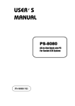
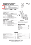
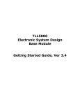
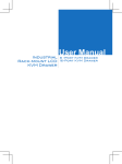
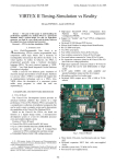
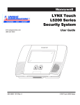
TLL5000 v1.1 documentation – User Manual
TLL5000
Electronic System Design
Base Module v1.1
User Manual
Copyright © 2008
The Learning Labs, Inc
UM-1
TLL5000 v1.1 documentation – User Manual
Copyright Notice
The Learning Labs, Inc. (“TLL”)
All rights reserved, 2008
Reproduction in any form without permission is prohibited.
Disclaimer
Information in this document is subject to change without notice and does not represent a
commitment on the part of TLL.
TLL provides this document as is, without warranty of any kind, expressed or implied, including,
but not limited to, the particular purpose. TLL may make improvements and/or changes in this
manual or in the products(s) and/or the program(s) described in this manual at any time.
Information in this manual is intended to be accurate and reliable. However, TLL assumes no
responsibility for its use, or for any infringements of rights of other parties, which may result
from its use.
This document could include technical or typographical errors. Changes are periodically made to
the information herein; these changes may be incorporated in new editions of the publication.
This manual is provided solely and exclusively for educational use,and this information or
related products should not be used nor relied upon for any purpose except for education and
training.
Technical Support
Please contact your local TLL authorized product representative for questions regarding
hardware, software or applications issues. Any updates or patches will be sent to you
automatically as long as your registration is current. The TLL products are designed to be
supported remotely by allowing viewing of the user’s desktop. It is highly recommended that
the PC from which you are using TLL products is connected to an Internet link that allows Web
browser access. In this way our technical support staff can view your desktop and work with
you to understand and solve technical issues.
Copyright © 2008
The Learning Labs, Inc
UM-2
TLL5000 v1.1 documentation – User Manual
Table of Contents:
1.
TLL5000 Electronic System Design Base Module .............................................................6
1.1. Features ...............................................................................................................6
1.2. General Description................................................................................................7
1.2.1. Block Diagram ................................................................................................7
1.2.2. Board Components ..........................................................................................8
1.2.3. Spartan3 FPGA................................................................................................8
1.2.4. ARM Housekeeping Processor ..........................................................................9
1.2.5. Power Supplies ...............................................................................................9
1.2.6. FPGA Configuration .........................................................................................9
1.2.7. System RAM ...................................................................................................9
1.2.8. System Flash ..................................................................................................9
1.2.9. Ethernet interface ...........................................................................................9
1.2.10.
Serial interfaces ......................................................................................... 10
1.2.11.
User LEDs, Switches, and Push Buttons ....................................................... 10
1.2.12.
VGA Output ............................................................................................... 10
1.2.13.
Video decoder ........................................................................................... 10
1.2.14.
Video encoder ........................................................................................... 10
1.2.15.
AC97 Audio CODEC .................................................................................... 10
1.2.16.
Expansion Connectors ................................................................................ 10
1.2.17.
SD-CARD interface ..................................................................................... 11
2. Using the System ....................................................................................................... 12
2.1. Power and Clock Distribution ................................................................................ 12
2.2. Configuring the FPGA ........................................................................................... 14
2.3. Using the SDRAM................................................................................................. 19
2.4. Using the System Flash ........................................................................................ 20
2.5. Using the XSGA output ......................................................................................... 21
2.6. Using the Video Encoder ...................................................................................... 22
2.7. Using the Video Decoder ...................................................................................... 23
2.8. Using the AC97 Audio Codec................................................................................. 24
2.9. Using the LEDs, Switches and Buttons ................................................................... 25
2.10.
Using the LCD Display....................................................................................... 26
2.11.
Using the Serial Port ......................................................................................... 26
2.12.
Using the Ethernet Network Interface ................................................................ 27
2.13.
Using the SD-Card ............................................................................................ 27
2.14.
Using the Mezzanine Expansion Connectors ........................................................ 28
2.15.
Enabling TLL5000 Board in the Base System Builder Wizard ................................. 31
3. Document history ....................................................................................................... 31
Copyright © 2008
The Learning Labs, Inc
UM-3
TLL5000 v1.1 documentation – User Manual
Figures:
Figure
Figure
Figure
Figure
Figure
Figure
Figure
Figure
Figure
Figure
Figure
Figure
1.1: TLL5000 Block Diagram .....................................................................................7
1.2: TLL5000 Board Photo ........................................................................................8
2.1: TLL5000 Monitor/Controller Initial Screen........................................................... 12
2.2: TLL5000 Monitor/Controller Power On Screen..................................................... 13
2.3: Operation Mode Selection: Prepare Configuration Files ........................................ 14
2.4: Selecting PROM file .......................................................................................... 15
2.5: Selecting a PROM with Design Revisioning Enabled ............................................. 15
2.6: Selecting an XCF32P PROM with 3 Revisions ..................................................... 16
2.7: Adding a device file .......................................................................................... 16
2.8: Adding the design file to revision 0 .................................................................... 17
2.9: Selecting configuration file for XCF32P ............................................................... 18
2.10: PROM programming options ............................................................................ 19
Copyright © 2008
The Learning Labs, Inc
UM-4
TLL5000 v1.1 documentation – User Manual
Tables:
Table 1.1: XC3S1500 Features .............................................................................................9
Table 2.1 FPGA revisions ................................................................................................... 14
Table 2.2 SDRAM to FPGA connection................................................................................. 19
Table 2.3 Flash to FPGA connection.................................................................................... 20
Table 2.4 VGA DAC connections to FPGA ............................................................................ 21
Table 2.5 Video encoder connection to FPGA ...................................................................... 22
Table 2.6 Video Decoder Schematic Connection .................................................................. 23
Table 2.7 AC97 codec connection with the FPGA ................................................................. 25
Table 2.8 Pushbutton connections ...................................................................................... 25
Table 2.9 LED connected to the FPGA................................................................................. 25
Table 2.10 DIP switches connected to the FPGA .................................................................. 26
Table 2.11 LCD connection with FPGA ................................................................................ 26
Table 2.12 RS232 connection to the FPGA ......................................................................... 27
Table 2.13 Jumper settings for the Ethernet interface .......................................................... 27
Table 2.14 SD-card interface connection to FPGA ................................................................ 27
Table 2.15 Mezzanine A connections with the FPGA ............................................................. 28
Table 2.16 Mezzanine B connection with the FPGA .............................................................. 29
Copyright © 2008
The Learning Labs, Inc
UM-5
TLL5000 v1.1 documentation – User Manual
1. TLL5000 Electronic System Design Platform (ESDP)
1.1. Features
•
•
•
•
•
•
•
•
•
•
•
•
•
•
•
•
•
•
•
•
•
•
•
Xilinx Spartan3 FPGA
ARM LPC2144 Housekeeping Processor
16MB SDRAM on-board
16MB FLASH on-board
High-speed SelectMAP FPGA configuration from Platform Flash In-System
Programmable Configuration PROM
On-board 10/100 Ethernet PHY device
Silicon Serial Number for unique board identification
SD/MMC card slot
RS-232 DB9 serial port
Two PS-2 serial ports
Eight LEDs connected to Spartan3 I/O pins
LCD 16 x 2 character display with backlight
Eight switches connected to Spartan3 I/O pins
Five push buttons connected to Spartan3 I/O pins
Two high-speed mezzanine board connectors joined to 80 Spartan3 I/O pins
AC-97 audio CODEC with audio amplifier and speaker/headphone output and line
level output
Microphone and line level audio input
On-board VGA output, 640 x 480 at 60 Hz supported by software) with added signal
generator capability
On-board video decoder with CVBS (composite), Y/C (S-video) and YPrPb
(component) video input support
On-board video encoder with with CVBS (composite), Y/C (S-video), YPrPb
(component) and EuroSCART RGB video output support
On-board power supplies
Power-on reset circuitry
Copyright © 2008
The Learning Labs, Inc
UM-6
TLL5000 v1.1 documentation – User Manual
1.2. General Description
The TLL5000 Development System provides an advanced hardware/software platform
that consists of a high-capacity Spartan3 Platform FPGA surrounded by a
comprehensive collection of peripheral components that can be used to create a
complex digital system.
1.2.1. Block Diagram
Figure 1.1 shows a block diagram of the TLL5000 Development System.
Figure 1.1: TLL5000 Development System Block Diagram
Copyright © 2008
The Learning Labs, Inc
UM-7
TLL5000 v1.1 documentation – User Manual
1.2.2. Board Components
This section contains a concise overview of several important components on the
TLL5000 Development System (see Figure 1.2).
Figure 1.2: TLL5000 Development System Board Photo
1.2.3. Spartan3 FPGA
U1 is a Xilinx Spartan3 XC3S1500 FPGA device packed in 676-lead fine-pitch ball grid
array package. All XC3S1500 key features can be seen in Table 1.1.
Copyright © 2008
The Learning Labs, Inc
UM-8
TLL5000 v1.1 documentation – User Manual
Table 1.1: XC3S1500 Features
Feature
Value
Equivalent Logic Cells
29952
Array Size
64 x 52
Distributed RAM
208 Kbits
Block RAM
576 Kbits
Dedicated Multipliers
32
DCMs
4
1.2.4. ARM Housekeeping Processor
ARM Housekeeping processor takes care of power up sequencing and monitoring of the
supply regulators. It also sets up and manages communications with host computer via
high USB connection.
1.2.5. Power Supplies
The TLL5000 Development System is powered from a DC 18Volt/3.5Amp regulated
power supply. On-board switching power supplies generate 5V, 3.3V, 2.5V, 1.8V and
1.2V for the FPGA and peripheral components.
ARM housekeeping processor is powered all the time and it has control over power
distribution to the rest of the board. All generated voltage levels are constantly
monitored by the housekeeping processor.
1.2.6. FPGA Configuration
FPGA can be programmed directly using the JTAG chain or indirectly using the onboard
Platform Flash. The Platform Flash device (XCF32PVO48C) can contain up to 4 FPGA
code revisions.
1.2.7. System RAM
The TLL5000 Development System has on board mounted Micron 1Meg x 32 x 4 Banks
SDRAM module.
1.2.8. System Flash
The TLL5000 Development System has on board mounted 128Mbit Spansion
S29GL128N Flash module.
1.2.9. Ethernet interface
The TLL5000 Development System provides an IEEE-compliant Fast Ethernet
transceiver that supports both 100BASE-TX and 10BASE-T applications. It supports full
duplex operation at 10 Mb/s and 100 Mb/s, with auto-negotiation and parallel
detection. The PHY provides a Media Independent Interface (MII) for attachment to
the 10/100 Media Access Controller (MAC) implemented in the FPGA. Each board is
equipped with a Silicon Serial Number that uniquely identifies it with a 48-bit serial
Copyright © 2008
The Learning Labs, Inc
UM-9
TLL5000 v1.1 documentation – User Manual
number. This serial number is retrieved using the “1-Wire” protocol. This serial number
can be used as the system MAC address.
1.2.10. Serial interfaces
The TLL5000 Development System provides three serial ports: a single RS-232 port
and two PS/2 ports. The RS-232 port supports hardware handshake and it uses a
standard DB-9 serial connector. This connector is typically used for communications
with a host computer using a standard 9-pin serial cable connected to a COM port. The
two PS/2 ports could be used to attach a keyboard and mouse to the TLL5000
Development System.
1.2.11. User LEDs, Switches, and Push Buttons
A total of eight LEDs are provided for user-defined purposes. Turning the LED on is
done by setting a logic 0 to the corresponding FPGA pin. Eight-position separate slideswitches and five push-button switches are provided for user input. The middle push
button is used as FPGA reset button.
1.2.12. VGA Output
The TLL5000 includes a video DAC and 15-pin high-density D-sub connector to support
XSGA output. The video DAC can operate with a pixel clock of up to 180 MHz. Only
VESA-compatible output of 640 x 480 at 60 Hz refresh is supported by software. It can
also be used as a 3-channel signal generator.
1.2.13. Video decoder
The TLL5000 includes an Analog Devices ADV7180 video decoder with CVBS
(composite), Y/C (S-video) and YPrPb (component) video input support. It supports
NTSC/PAL/SECAM video standards with additional video standard autodetection
feature.
1.2.14. Video encoder
The TLL5000 offers composite, Y/C (S-video) and YPrPb (component) video output
support provided by Analog Devices ADV7173 video encoder.
1.2.15. AC97 Audio CODEC
An audio CODEC and stereo power amplifier are included on the TLL5000 to provide a
high-quality audio path and provide all of the analog functionality in a PC audio system.
It features a full-duplex stereo ADC and DAC, with an analog mixer, combining the linelevel inputs, microphone input, and PCM data.
1.2.16. Expansion Connectors
The includes two 80 pin (2 x 40) mezzanine board connectors. Every connector
provides 40 Spartan3 I/O pins, JTAG signals, two differential clocks synchronized to the
on-board 100Mhz master clock, and 3.3V/3.5A and 18V/0.5A power supply lines.
Copyright © 2008
The Learning Labs, Inc
UM-10
TLL5000 v1.1 documentation – User Manual
1.2.17. SD-CARD interface
The TLL5000 system includes a header for SD and MMC cards which enable users to
store their data on a removable media.
Copyright © 2008
The Learning Labs, Inc
UM-11
TLL5000 v1.1 documentation – User Manual
2. Using the System
2.1. Power and Clock Distribution
Before starting TLL5000 Monitor/Controller application the TLL5000 should be
connected to the PC using ARM USB port. TLL5000 Monitor/Controller application initial
screen is shown in Figure 2.1.
Figure 2.1: TLL5000 Monitor/Controller Initial Screen
First TLL5000 Development Board device should be selected using circled drop-down
box. After that board can be powered up using Power button. After powering up, the
TLL5000 Monitor/Controller screen should look like it is shown in Figure 2.2.
Copyright © 2008
The Learning Labs, Inc
UM-12
TLL5000 v1.1 documentation – User Manual
Figure 2.2: TLL5000 Monitor/Controller Power On Screen
1. Power Values Monitor shows current power supply levels with their valid ranges.
2. FPGA (R/W) provides FPGA OPB read/write functionality. It can be used for debug
purposes.
3. CPLD (R/W) provides CPLD registers read/write functionality. It can be used for
debug purposes.
4. AD9510 Clock Divider input clock selection. External clock (Clk 1) or on-board
generated 100MHz clock (Clk 2) can be selected as Clock Divider input clock.
5. AD9510 Clock Divider manual register access. It should be used if desired clock
distribution can not be obtained using controls 6 and 7.
6. Four LVPECL Clock Divider outputs settings. Divide value and phase offset can be
individually adjusted for each channel. Channel setting is implemented by pressing
the corresponding set button.
7. Two selectable CMOS/LVDS and two CMOS Clock Divider outputs settings. Divide
value and phase offset can be individually adjusted for each channel. For
Mezzanine clock outputs LVDS or CMOS signal standards can be selected. Channel
setting is implemented by pressing the corresponding set button.
Copyright © 2008
The Learning Labs, Inc
UM-13
TLL5000 v1.1 documentation – User Manual
2.2. Configuring the FPGA
The FPGA is programmed from Xilinx ISE or EDK software during FPGA software
development. This is done by selecting menu entry Device configuration/ Download
bitstream.
During power-up of the board, the FPGA can be programmed by one of four available
revisions inside Xilinx Platform flash XCF32P. To enable multiple revisions, place switch
1 from DIP switch pack S1 to position “1”. To select the desired revision, use switches
2 and 3 from the same pack
Table 2.1: FPGA revisions
Position of
switch 2
1
0
1
1
Position of
switch 3
1
1
0
1
Revision number
Default function
0
1
2
3
Peripheral tests except video and Ethernet
Memory tests
Video and Ethernet tests
No default function
To prepare a PROM file with multiple revisions, proceed as follows:
The .bit file created by the Xilinx implementation tools must be converted to an .MCS
file before it can be programmed into the Platform FLASH PROM.
1. Start iMPACT and select Prepare Configuration Files as shown in Figure 2.3.
Figure 2.3: Operation Mode Selection: Prepare Configuration Files
2. Click on Next and select PROM File in the Prepare Configuration Files option menu
shown in Figure 2.4.
Copyright © 2008
The Learning Labs, Inc
UM-14
TLL5000 v1.1 documentation – User Manual
Figure 2.4: Selecting PROM file
3. Click on Next and then select Xilinx PROM with Design Revisioning Enabled using
the MCS PROM File Format.
Figure 2.5: Selecting a PROM with Design Revisioning Enabled
4. Give the PROM File a name of your choice in the location of your choice as shown in
Figure 2.5.
Note: Do NOT select Compress Data, because the TLL5000 development System
hardware does not support this option.
Copyright © 2008
The Learning Labs, Inc
UM-15
TLL5000 v1.1 documentation – User Manual
Figure 2.6: Selecting an XCF32P PROM with 3 Revisions
5. Click on Next to bring up the option screen where the type of PROM is specified.
6. Select the XCF32P PROM from the drop down men. Click on the “Add” button and
specify “3” from the Number of Revisions drop down menu as shown in Figure 2.6.
7. Click on Next twice to bring up the Add Device File screen shown in Figure 2.7.
Figure 2.7: Adding a device file
8. Click on Add File and navigate to your design directory and select the .bit file for
your design as shown in Figure 2.8.
Copyright © 2008
The Learning Labs, Inc
UM-16
TLL5000 v1.1 documentation – User Manual
Figure 2.8: Adding the design file to revision 0
9. Click on Open and answer No when prompted to add another design file to Revision
0.
10. Note that Revision 0 is highlighted in green; this is where the “known” configuration
will be placed in the PROM. By selecting your design file for Revision 0, you are just
reserving space in the PROM for the known configuration.
If the design file was created with the Startup Clock set to JTAG, iMPACT will issue
a warning that the Startup Clock will be changed to CCLK in the bitstream
programmed into the PROM. This warning can be safely ignored.
11. Once you answer No when prompted to add another design file to Revision 0, the
green revision highlight will move to Revision 1. You will be prompted to add your
design file to Revision 1. By selecting your design file for Revision 0, you are just
reserving space in the PROM for the known configuration.
12. Click on Open and answer No when prompted to add another design file to Revision
1.
13. Once you answer No when prompted to add another design file to Revision 1, the
green revision highlight will move to Revision 2. You will be prompted to add you
design file to Revision 2.
14. Click on Open and answer No when prompted to add another design file to Revision
1. Click on Finish to start the generation of the MCS
15. After iMPACT successfully creates the MCS file, select Configuration Mode from the
Mode menu.
16. Make sure that TLL5000 is powered up and that a PC4 cable connects the board to
the PC that is running the iMPACT software.
17. Select the Initialize Chain command. The iMPACT software then interrogates the
system and reports that there are three devices in the JTAG chain. The first device
is the XCF32P PROM; the second device is the CPLD; and the third device is the
Spartan 3 FPGA.
Copyright © 2008
The Learning Labs, Inc
UM-17
TLL5000 v1.1 documentation – User Manual
18. Select the MCS file that you created earlier as the configuration file for the XCF32P
PROM and click Open, as shown in Figure 7.
19. Select BYPASS as the configuration files for the CPLD and the Spartan 3 FPGA.
20. Right mouse click on the icon for the XCF32P PROM and select Program from the
drop down menu as shown in Figure.
21. The iMPACT software responds with a form that allows the user to specify which
design revisions are to be programmed and the programming options for the
various revisions. De-select Design Revision Rev 0 and Rev 1 and all of the options
for these revisions to minimize the programming time.
Figure 2.9: Selecting configuration file for XCF32P
Copyright © 2008
The Learning Labs, Inc
UM-18
TLL5000 v1.1 documentation – User Manual
Figure 2.10: PROM programming options
22. Select Design Revision Rev 2, and set the Erase (ER) bit to erase any previous
“User” design. Make sure that the Write Protect (WP) bit is not set.
23. Verify that the Operating Mode is set to Slave and the I/O Configuration is set to
Parallel Mode as shown in Figure 2.10.
24. Click on OK to begin programming the PROM
2.3. Using the SDRAM
The TLL5000 board is equipped with a single 16Mb SDRAM IC, Micron
MT48LC4M32B2P which is connected directly to Bank 3 of the FPGA. FPGA to SDRAM
connection list is shown in Table 2.2.
Table 2.2: SDRAM to FPGA connection
FPGA
BALL
P26
P25
P24
P23
P22
P21
P20
P19
R26
R25
SCH Net
Name
RAM_IO0
RAM_IO1
RAM_IO2
RAM_IO3
RAM_IO4
RAM_IO5
RAM_IO6
RAM_IO7
RAM_IO8
RAM_IO9
Copyright © 2008
The Learning Labs, Inc
Interface
Signal Name
DQ1
DQ0
DQ13
DQ12
DQ14
DQ15
DQ2
CLK
DQ4
DQ3
FPGA
BALL
V25
V24
V23
V22
U20
V20
W26
W25
W24
W23
SCH Net
Name
RAM_IO28
RAM_IO29
RAM_IO30
RAM_IO31
RAM_IO32
RAM_IO33
RAM_IO34
RAM_IO35
RAM_IO36
RAM_IO37
Interface
Signal Name
CS#
DQ29
DQ28
A0
A6
DQM3
BA1
A11
DQ27
DQ26
UM-19
TLL5000 v1.1 documentation – User Manual
R24
T23
R22
R21
R20
R19
T26
T25
T22
T21
T20
T19
U26
U25
U24
U23
U22
U21
RAM_IO10
RAM_IO11
RAM_IO12
RAM_IO13
RAM_IO14
RAM_IO15
RAM_IO16
RAM_IO17
RAM_IO18
RAM_IO19
RAM_IO20
RAM_IO21
RAM_IO22
RAM_IO23
RAM_IO24
RAM_IO25
RAM_IO26
RAM_IO27
DQ11
DQ9
DQ10
DQ5
A8
CKE
DQ7
DQ6
RAS#
DQM0
A7
A9
CAS#
WE#
DQ8
DQM1
BA0
A5
V21
W22
Y26
Y25
W21
W20
AA26
AA25
Y23
Y22
AA24
AA23
AB26
AB25
Y21
Y20
AC26
AC25
RAM_IO38
RAM_IO39
RAM_IO40
RAM_IO41
RAM_IO42
RAM_IO43
RAM_IO44
RAM_IO45
RAM_IO46
RAM_IO47
RAM_IO48
RAM_IO49
RAM_IO50
RAM_IO51
RAM_IO52
RAM_IO53
RAM_IO54
RAM_IO55
A4
DQM2
A11
A10
A3
DQ31
DQ16
A2
DQ25
DQ18
DQ25
DQ23
DQ19
DQ17
DQ21
DQ30
DQ22
DQ20
The memory has 1 Meg x 32 x 4 banks. It uses 12 address lines (A0-A11) for row
addressing and 8 address lines (A0-A7) for column addressing. It has 4 banks,
maximum operating frequency of 143MHz and CAS latency CL=3. A generic Xilinx
SDRAM controller (OPB_SDRAM) IP is used to enable access to SDRAM in the design.
2.4. Using the System Flash
The TLL5000 board is equipped with a Spansion S29GL-N MirrorBit™ Flash Family
device. The Flash IP enables access to the flash with the following commands: read,
erase sector, erase chip, write word, write buffer.
The connection between the Flash and the FPGA is given in Table 2.3.
FPGA
BALL
F6
F5
E4
E3
D2
D1
G7
G6
E2
E1
F4
F3
SCH Net
Name
FLASH_IO0
FLASH_IO1
FLASH_IO2
FLASH_IO3
FLASH_IO4
FLASH_IO5
FLASH_IO6
FLASH_IO7
FLASH_IO8
FLASH_IO9
FLASH_IO10
FLASH_IO11
Copyright © 2008
The Learning Labs, Inc
Table 2.3: Flash to FPGA connection
Interface Signal
FPGA
SCH Net
Name
BALL
Name
WE#
H3
FLASH_IO23
A21
H2
FLASH_IO24
A0
H1
FLASH_IO25
CE#
J7
FLASH_IO26
DQ2
K7
FLASH_IO27
DQ9
J5
FLASH_IO28
A22
J4
FLASH_IO29
RESET#
J3
FLASH_IO30
DQ3
J2
FLASH_IO31
DQ10
K6
FLASH_IO32
OE#
K5
FLASH_IO33
DQ0
K4
FLASH_IO34
Interface Signal
Name
A5
DQ6
DQ13
A14
A10
A18
A4
A3
DQ14
A11
A17
A2
UM-20
TLL5000 v1.1 documentation – User Manual
G5
G4
F2
F1
H7
H6
G2
G1
H5
J6
H4
FLASH_IO12
FLASH_IO13
FLASH_IO14
FLASH_IO15
FLASH_IO16
FLASH_IO17
FLASH_IO18
FLASH_IO19
FLASH_IO20
FLASH_IO21
FLASH_IO22
WP#
DQ8
DQ4
DQ11
A15
A13
DQ5
DQ12
RY/BY#
A12
DQ1
K3
K2
K1
L8
L7
L6
L5
L2
L1
M8
M7
FLASH_IO35
FLASH_IO36
FLASH_IO37
FLASH_IO38
FLASH_IO39
FLASH_IO40
FLASH_IO41
FLASH_IO42
FLASH_IO43
FLASH_IO44
FLASH_IO45
A1
DQ15/A_1
DQ7
A19
A9
A6
A7
A16
BYTE#
A20
A8
2.5. Using the XSGA output
The TLL5000 board is equipped with a triple 8-bit DAC ADV7125 (U402), a high density
15-pin D-Sub connector (CON203B), and IP placed in the FPGA. The data inputs and
control signals are converted into analog current outputs that can drive 25Ω to 37.5Ω
loads, corresponding to a doubly-terminated 50Ω to 75Ω load. The BLANK input
overrides the RGB inputs and blanks the display output.
The provided FPGA IP enables reading the desired output pattern from a memory area
inside the SDRAM and outputting it to the D-Sub connector. The connections with the
FPGA are given in Table 2.4.
Table 2.4: VGA DAC connections to FPGA
Table 2.4: VGA DAC connections to FPGA
FPGA
BALL
W1
V6
U7
V5
V4
V3
V2
U6
U5
U4
U3
U2
U1
T8
T7
T6
T5
T2
T1
Copyright © 2008
The Learning Labs, Inc
Schematic Net
Name
VDAC_IO0
VDAC_IO1
VDAC_I02
VDAC_IO3
VDAC_IO4
VDAC_IO5
VDAC_IO6
VDAC_IO7
VDAC_IO8
VDAC_IO9
VDAC_IO10
VDAC_IO11
VDAC_IO12
VDAC_IO13
VDAC_IO14
VDAC_IO15
VDAC_IO16
VDAC_IO17
VDAC_IO18
Interface Signal
Name
B1
#SYNC
#BLANK
G0
R6
R5
B2
G2
G1
R4
R3
B3
B4
G6
G7
G3
R1
B5
B6
UM-21
TLL5000 v1.1 documentation – User Manual
R8
R7
R6
R5
T4
R3
R2
R1
P8
VDAC_IO19
VDAC_IO20
VDAC_IO21
VDAC_IO22
VDAC_IO23
VDAC_IO24
VDAC_IO25
VDAC_IO26
VDAC_IO27
G5
R7
G4
#PSAVE
R2
R0
B7
CLOCK
B0
2.6. Using the Video Encoder
The board has an ADV7173 video encoder. It is an integrated Digital Video Encoder
that converts digital CCIR-601 4:2:2 8-bit component video data into a standard analog
baseband television signal compatible with world wide standards.
There are six DACs available on the ADV7173. In addition to the Composite output
signal there is the facility to output S-VHS Y/C Video, RGB Video and YUV Video. The
on-board SSAF (Super Sub-Alias Filter), with extended luminance frequency response
and sharp stopband attenuation, enables studio quality video playback on modern TVs,
giving optimal horizontal line resolution. An additional sharpness control feature allows
extra luminance boost on the frequency response. A PC’98-Compliant autodetect
feature has been added to allow the user to determine whether or not the DACs are
correctly terminated. If not, the ADV7173 flags that they are not connected through
the Status bit and provides the option of automatically powering them down, thereby
reducing power consumption. The ADV7173 also supports both PAL and NTSC square
pixel operation. The parts also incorporate WSS and CGMS-A data control generation.
The output video frames are synchronized with the incoming data Timing Reference
Codes. Optionally the encoder accepts (and can generate) HSYNC, VSYNC, and FIELD
timing signals. These timing signals can be adjusted to change pulsewidth and position
while the part is in the master mode. The Encoder requires a single two times pixel rate
(27 MHz) clock for standard operation. Alternatively the Encoder requires a 24.5454
MHz clock for NTSC or 29.5 MHz clock for PAL square pixel mode operation. All internal
timing is generated on-chip.
HSO/CSO and VSO TTL outputs, synchronous to the analog output video, are also
available. A programmable CLAMP output signal is also available to enable clamping in
either the front or back porch of the video signal. A separate teletext port enables the
user to directly input teletext data during the vertical blanking interval.
Table 2.5 shows the connection list between the FPGA and the video encoder. The
provided FPGA IP enables reading out a region of SDRAM memory containing CCIR-601
data stream and sending it to the encoder circuitry. The video encoder can be used
stand-alone or together with the video decoder circuit.
Table 2.5: Video encoder connection to FPGA
FPGA
BALL
Copyright © 2008
The Learning Labs, Inc
Schematic Net
Name
Interface Signal
Name
UM-22
TLL5000 v1.1 documentation – User Manual
AB2
AB1
Y7
Y6
AA4
AA3
Y5
Y4
AA2
AA1
Y2
Y1
W7
W6
W5
V7
W4
W3
W2
VENC_IO0
VENC_IO1
VENC_IO2
VENC_IO3
VENC_IO4
VENC_IO5
VENC_IO6
VENC_IO7
VENC_IO8
VENC_I09
VENC_IO10
VENC_IO11
VENC_IO12
VENC_IO13
VENC_IO14
VENC_IO15
VENC_IO16
VENC_IO17
VENC_IO18
P1
P2
TTX
#CSO/#HSO
P0
#VSO
FIELD/#VSYNC
#RESET
P3
P4
P5
P6
TTXREQ
#HSYNC
#BLANK
SCRESET/RTC
PAL/#NTSC
CLAMP
P7
2.7. Using the Video Decoder
The TLL5000 contains a video decoder circuitry, ADV7180, enabling conversion from
standard analog PAL/NTSC video signal to CCIR-601 data.
The ADV7180 automatically detects and converts standard analog baseband television
signals compatible with worldwide NTSC, PAL, and SECAM standards into 4:2:2
component video data compatible with the 8-bit ITU-R BT.656 interface standard.
External HS, VS, and FIELD signals provide timing references for LCD controllers and
other video ASICs, if required The accurate 10-bit analog-to-digital conversion provides
professional quality video performance for consumer applications with true 8-bit data
resolution. Three analog video input channels accept standard composite, S-video, or
component video signals, supporting a wide range of consumer video sources. AGC and
clamp-restore circuitry allow an input video signal peak-to-peak range up to 1.0 V.
Alternatively, these can be bypassed for manual settings.
The provided IP core enables setting ADV7180 registers using I2C and receiving CCIR601 data and storing it to SDRAM memory from where it can be read by the video
encoder or a user application. Connections to the FPGA are given in Table 2.6.
Table 2.6: Video Decoder Schematic Connection
FPGA
BALL
AD2
AD1
AB4
AB3
Copyright © 2008
The Learning Labs, Inc
Schematic Net
Name
VDEC_IO0
VDEC_IO1
VDEC_IO2
VDEC_IO3
Interface Signal Name
#RESET
P1
P2
LCC
UM-23
TLL5000 v1.1 documentation – User Manual
AC2
AC1
AA6
AB6
AD5
AC6
AD6
AC7
AC8
AD8
AC9
VDEC_IO4
VDEC_IO5
VDEC_IO6
VDEC_IO7
VDEC_IO8
VDEC_IO9
VDEC_IO10
VDEC_IO11
VDEC_IO12
VDEC_IO13
VDEC_IO14
P0
#PWRDWN
P3
P4
P5
P6
P7
SFL
HS
#INTRQ
VS/FIELD
2.8. Using the AC97 Audio Codec
The TLL5000 has an AC97 rev 2.3 compliant IC, AD1981BL. It can be used to record
and play audio, but also for basic signal acquisition and generation at audio
frequencies.
AD1981BL characteristics include:
•
•
•
•
•
•
•
•
•
•
•
•
•
•
•
•
•
•
•
•
•
•
•
S/PDIF output, 20-bit data format, supporting 48 kHz and 44.1 kHz sample rates
Integrated stereo headphone amplifier
Variable sample rate audio
External audio power-down control
>90 dB dynamic range
Stereo full-duplex codec
20-bit PCM DAC
3 analog line-level stereo inputs for line-in, AUX, and CD
Mono line-level phone input
Dual MIC input with built-in programmable preamplifier
High quality CD input with ground sense
Mono output for speakerphone or internal speaker
power management support
Stereo MIC preamplifier support
Built-in digital equalizer function for optimized
speaker sound
Full-duplex variable sample rates from 7040 Hz to
48 kHz with 1 Hz resolution
Jack sense pins for automatic output switching
Software-programmed VREFOUT output for biasing
microphone and external power amplifier
Low power 3.3 V operation for analog and digital supplies
Multiple codec configuration options
The provided IP is a Xilinx IP enabling access to the registers of AD1981BL. Additional
software functions enable the user to record a 10sec long recording to the SDRAM
memory and play it back through the headphones, as well as set input and output
gains.
Copyright © 2008
The Learning Labs, Inc
UM-24
TLL5000 v1.1 documentation – User Manual
Table 2.7: AC97 codec connection with the FPGA
FPGA
BALL
P7
P6
P5
P4
P3
P2
P1
Schematic Net
Name
AC97_IO0
AC97_IO1
AC97_IO2
AC97_IO3
AC97_IO4
AC97_IO5
AC97_IO6
Interface Signal
Name
SDATA_IN
BIT_CLK
SDATA_OUT
#ID_1
#ID_0
SYNC
#RESET
2.9. Using the LEDs, Switches and Buttons
The TLL5000 board has 8 surface-mounted LED diodes, 5 push-button switches and 8
slide-switches.
The LED diodes are illuminated when the user outputs a logical “1” to the appropriate
pin of the FPGA (Table 2.9), and they are off when a logical “0” is outputted to a pin.
Series resistors limit the current to about 4mA when the Led is illuminated.
5 pushbuttons are in placed on tips of an imaginary diamond-form shape, giving the
user the form of a gamepad. When a button is pressed, it generates a logic “0” o the
pin of the FPGA, while logic “1” is generated when a button is not pressed. Table 2.8
shows which pins of the FPGA are connected to which push-button.
Table 2.8: Pushbutton connections
FPGA
BALL
AF13
AB24
AB23
AA22
AA21
Schematic Net
Name
UI_JOY0
UI_JOY1
UI_JOY2
UI_JOY3
UI_JOY4
Interface Signal Name
UI_JOY0
UI_JOY1
UI_JOY2
UI_JOY3
UI_JOY4
Table 2.9: LED connected to the FPGA
FPGA BALL
AB7
AB8
AB9
AA9
AA10
AA11
AD12
Y13
Schematic Net
Name
UI_LED0
UI_LED1
UI_LED2
UI_LED3
UI_LED4
UI_LED5
UI_LED6
UI_LED7
Interface Signal Name
UI_LED0
UI_LED1
UI_LED2
UI_LED3
UI_LED4
UI_LED5
UI_LED6
UI_LED7
8 slide-switches are placed in line on the board. When the switch is on, it generates
logic “0” on the pin of the FPGA to which it is connected, while logic “1” is generated
Copyright © 2008
The Learning Labs, Inc
UM-25
TLL5000 v1.1 documentation – User Manual
when a switch is off. Table 2.10 shows which pins of the FPGA are connected to which
DIP switch.
Table 2.10: DIP switches connected to the FPGA
FPGA
BALL
Y8
Y9
Y10
Y11
Y12
W11
W12
W13
Schematic Net
Name
UI_SW0
UI_SW1
UI_SW2
UI_SW3
UI_SW4
UI_SW5
UI_SW6
UI_SW7
Interface Signal Name
UI_SW0
UI_SW1
UI_SW2
UI_SW3
UI_SW4
UI_SW5
UI_SW6
UI_SW7
A generic Xilinx IP core, opb_gpio is used to access all these peripherals.
2.10. Using the LCD Display
The LCD display onboard TLL5000 consists of a Display electronic GmbH LCD module
SYH 16216 SYH-LY which uses a Hitachi HD44780 LCD controller in 4 bit mode. A Xilinx
IP core, opb_gpio_v3_01_b is used to access this peripheral, while additional software
functions are given which enable resetting the LCD controller and writing on line or
line 2 of the LCD.
Table 2.11 shows FPGA to LCD connection list.
Table 2.11: LCD connection with FPGA
FPGA
BALL
J22
K22
K21
L21
M21
N21
M20
N20
Schematic Net
Name
LCD_IO0
LCD_IO1
LCD_IO2
LCD_IO3
LCD_IO4
LCD_IO5
LCD_IO6
LCD_IO7
Interface Signal
Name
LCD_D3
LCD_D2
LCD_D1
LCD_D0
LCD_EN
LCD_R/#W
LCD_RS
LCD_L+
2.11. Using the Serial Port
The TLL5000 Development System has a single RS-232 port. The RS-232 port is
configured as a Data Communication Equipment (DCE) with hardware handshake using
a standard DB-9 serial connector. Considering the +/-12V logic levels on RS232
connectors, a ADM3202 high speed RS232/v.28 interface from Analog Devices is used
for coupling.
The FPGA IP core which is used for RS232 is Xilinx opb_uartlite_v1_00_a core.
Functions are provided which enable sending messages from the TLL5000 to the PC,
but also receiving user input from the PC.
Copyright © 2008
The Learning Labs, Inc
UM-26
TLL5000 v1.1 documentation – User Manual
Table 2.12: RS232 connection to the FPGA
FPGA
BALL
M1
M2
N1
M6
Schematic Net
Name
RS232_RX
RS232_TX
RS232_CTS
RS232_RTS
Interface Signal
Name
RS232_RX
RS232_TX
RS232_CTS
RS232_RTS
2.12. Using the Ethernet Network Interface
The Ethernet interface on TLL5000 is based on Intel’s PHY LXT972A chip. It’s a singlePort 10/100 Mbps PHY Transceiver which directly supports both 100BASE-TX and
10BASE-T applications. It supports full-duplex operation at 10Mbs and 100Mbs.
Operating conditions for the LXT972A Transceiver can be set using auto-negotiation,
parallel detection, or manual control. The transceiver requires only a single 2.5 or 3.3 V
power supply with 2.5 V MII interface support.
The Ethernet interface uses a standard Xilinx IP core, opb_ethernetlite which ships with
Xilinx EDK software with a hardware evaluation license. Additional functions are given
which enable verifying the interface functionality using the TLL5000 desktop software.
There are a number of jumpers around the Ethernet PHY, the explanation is given in
Table 2.13.
Table 2.13: Jumper settings for the Ethernet interface
Jumper designator
JS200
JS201
Default position
Open
Open
JS202
Open
JS203
Connected to GND
Description
TX output slew rate setting
TX output slew rate setting
Pause capability advertising
during negotiation
Device address setting
2.13. Using the SD-Card
The TLL5000 Development Board has a single SD Card slot directly connected to the
FPGA. Electrical interface specification along with communication SPI (serial bus
standard established by Motorola) access protocol for SD cards is accomplished with
“SD Card Physical Layer System Specification, Version 1.01” defined by SD Card
Association.
Communication is implemented with Xilinx SPI IP core opb_spi_v1_00_d. Additional
functions are provided which enable initializing the card, reading it’s size and block read
and write. The connection to the FPGA is given in Table 2.14.
Table 2.14: SD-card interface connection to FPGA
FPGA BALL
Schematic Net Name
Interface Signal Name
J21
K20
MMC_IO0
MMC_IO1
DI/CD/CMD
SW_CI
Copyright © 2008
The Learning Labs, Inc
UM-27
TLL5000 v1.1 documentation – User Manual
H21
J20
L19
L20
M19
N19
MMC_IO2
MMC_IO3
MMC_IO4
MMC_IO5
MMC_IO6
MMC_IO7
CD/DAT3
DAT2
Do/DAT0
CLK
DAT1
SW_WP
2.14. Using the Mezzanine Expansion Connectors
The TLL-5000 is able to accept two Mezzanine expansion modules (80 pins/module),
and these are intended to provide the expansion capability to allow for complementary
processing (RISC, DSP, …) and interface (analog, power, wireless, …) modules needed
for prototyping advanced electronic systems. For that purpose two pairs of high speed
Samtec connectors (for mezzanine board A and B) are implemented on the board. Each
of the interface consist of 80 bits wide bus connected to FPGA, I2C bus, +3.3V and
+18V power, two differential (or selectable one single ended and one LVPECL) clocks
from clock generator subsystem, and dedicated JTAG lines.
The connectors are symmetrical both in electrical and physical sense, giving the
opportunity to use both pair of connectors equally.
The 18V and 3.3V power supplies are brought to connectors for powering up the
mezzanine boards. The 80 bit interface is routed as high speed 50ohm lines, with
equalized line length to achieve signal integrity for a wide range of possible mezzanine
boards.
High speed connectors QTE-40-02-L-D-A-K from Samtec are used for the mezzanine
boards interconnecting. Mating connectors on the mezzanine boards should be QSE-4001-L-D-A-K. Please refer to manufacturer resources for more detailed information on
the connectors.
FPGA to mezzanine connectors A and B connection list is shown in Table 2.15 and
Table 2.16 respectively.
Table 2.15: Mezzanine A connections with the FPGA
FPGA
BALL
AF15
AE15
AF16
AE16
AF17
AE17
AE18
AF19
AE19
AF20
AE20
SCH Net
Name
MZ_IO_A0
MZ_IO_A1
MZ_IO_A2
MZ_IO_A3
MZ_IO_A4
MZ_IO_A5
MZ_IO_A6
MZ_IO_A7
MZ_IO_A8
MZ_IO_A9
MZ_IO_A10
Copyright © 2008
The Learning Labs, Inc
Interface Signal
Name
CON900.25
CON900.27
CON900.31
CON900.33
CON900.35
CON900.37
CON900.41
CON900.43
CON900.45
CON900.47
CON900.51
FPGA
BALL
AD22
AC21
AD21
AC20
AC19
AD19
AC18
AD18
AC17
AD17
AC16
SCH Net
Name
MZ_IO_A40
MZ_IO_A41
MZ_IO_A42
MZ_IO_A43
MZ_IO_A44
MZ_IO_A45
MZ_IO_A46
MZ_IO_A47
MZ_IO_A48
MZ_IO_A49
MZ_IO_A50
Interface Signal
Name
CON901.21
CON901.23
CON901.25
CON901.27
CON901.31
CON901.33
CON901.35
CON901.37
CON901.41
CON901.43
CON901.45
UM-28
TLL5000 v1.1 documentation – User Manual
AF21
AE21
AF22
AE22
AF23
AE23
AF24
AE24
AD25
AB20
AA20
W15
W16
Y16
Y17
Y18
AA18
AA19
Y19
AC22
AD23
AB21
AB22
AA15
AA16
AA17
AB17
AB18
AB19
MZ_IO_A11
MZ_IO_A12
MZ_IO_A13
MZ_IO_A14
MZ_IO_A15
MZ_IO_A16
MZ_IO_A17
MZ_IO_A18
MZ_IO_A19
MZ_IO_A20
MZ_IO_A21
MZ_IO_A22
MZ_IO_A23
MZ_IO_A24
MZ_IO_A25
MZ_IO_A26
MZ_IO_A27
MZ_IO_A28
MZ_IO_A29
MZ_IO_A30
MZ_IO_A31
MZ_IO_A32
MZ_IO_A33
MZ_IO_A34
MZ_IO_A35
MZ_IO_A36
MZ_IO_A37
MZ_IO_A38
MZ_IO_A39
CON900.53
CON900.55
CON900.57
CON900.61
CON900.63
CON900.65
CON900.67
CON900.71
CON900.73
CON900.75
CON900.77
CON900.26
CON900.28
CON900.32
CON900.34
CON900.36
CON900.38
CON900.42
CON900.44
CON900.46
CON900.48
CON900.52
CON900.54
CON900.56
CON900.58
CON900.62
CON900.64
CON900.66
CON900.68
AB16
AD15
AB15
AB14
AC11
AB10
AD10
AC10
AD9
AA8
AA7
AF4
AD4
AE12
AF12
AE11
AF11
AE10
AF10
AE9
AE8
AF8
AE7
AF7
AE6
AF6
AE5
AF5
AE4
MZ_IO_A51
MZ_IO_A52
MZ_IO_A53
MZ_IO_A54
MZ_IO_A55
MZ_IO_A56
MZ_IO_A57
MZ_IO_A58
MZ_IO_A59
MZ_IO_A60
MZ_IO_A61
MZ_IO_A62
MZ_IO_A63
MZ_IO_A64
MZ_IO_A65
MZ_IO_A66
MZ_IO_A67
MZ_IO_A68
MZ_IO_A69
MZ_IO_A70
MZ_IO_A71
MZ_IO_A72
MZ_IO_A73
MZ_IO_A74
MZ_IO_A75
MZ_IO_A76
MZ_IO_A77
MZ_IO_A78
MZ_IO_A79
CON901.47
CON901.51
CON901.53
CON901.55
CON901.57
CON901.61
CON901.63
CON901.65
CON901.67
CON901.71
CON901.73
CON901.75
CON901.77
CON901.22
CON901.24
CON901.26
CON901.28
CON901.32
CON901.34
CON901.36
CON901.38
CON901.46
CON901.48
CON901.50
CON901.52
CON901.56
CON901.58
CON901.60
CON901.62
Table 2.16: Mezzanine B connection with the FPGA
FPGA
BALL
F21
F20
E21
E20
E19
E18
F18
F17
F16
F15
G14
G13
SCH Net
Name
MZ_IO_B0
MZ_IO_B1
MZ_IO_B2
MZ_IO_B3
MZ_IO_B4
MZ_IO_B5
MZ_IO_B6
MZ_IO_B7
MZ_IO_B8
MZ_IO_B9
MZ_IO_B10
MZ_IO_B11
Copyright © 2008
The Learning Labs, Inc
Interface Signal
Name
CON902.25
CON902.27
CON902.31
CON902.33
CON902.35
CON902.37
CON902.41
CON902.43
CON902.45
CON902.47
CON902.51
CON902.53
FPGA
BALL
B3
A3
B4
E5
E6
C4
D5
C5
D6
C6
D7
D8
SCH Net
Name
MZ_IO_B40
MZ_IO_B41
MZ_IO_B42
MZ_IO_B43
MZ_IO_B44
MZ_IO_B45
MZ_IO_B46
MZ_IO_B47
MZ_IO_B48
MZ_IO_B49
MZ_IO_B50
MZ_IO_B51
Interface Signal
Name
CON903.21
CON903.23
CON903.25
CON903.27
CON903.31
CON903.33
CON903.35
CON903.37
CON903.41
CON903.43
CON903.45
CON903.47
UM-29
TLL5000 v1.1 documentation – User Manual
G12
F13
F12
F11
F10
E10
E9
E8
E7
F7
G19
F19
G18
G17
G16
G15
H16
H15
H14
H13
H12
H11
G11
G10
G9
F9
F8
G8
MZ_IO_B12
MZ_IO_B13
MZ_IO_B14
MZ_IO_B15
MZ_IO_B16
MZ_IO_B17
MZ_IO_B18
MZ_IO_B19
MZ_IO_B20
MZ_IO_B21
MZ_IO_B22
MZ_IO_B23
MZ_IO_B24
MZ_IO_B25
MZ_IO_B26
MZ_IO_B27
MZ_IO_B28
MZ_IO_B29
MZ_IO_B30
MZ_IO_B31
MZ_IO_B32
MZ_IO_B33
MZ_IO_B34
MZ_IO_B35
MZ_IO_B36
MZ_IO_B37
MZ_IO_B38
MZ_IO_B39
Copyright © 2008
The Learning Labs, Inc
CON902.55
CON902.57
CON902.61
CON902.63
CON902.65
CON902.67
CON902.71
CON902.73
CON902.75
CON902.77
CON902.26
CON902.28
CON902.32
CON902.34
CON902.36
CON902.38
CON902.42
CON902.44
CON902.46
CON902.48
CON902.52
CON902.54
CON902.56
CON902.58
CON902.62
CON902.64
CON902.66
CON902.68
C8
D9
C9
D10
C10
D11
E11
C12
E12
C13
D13
E13
A4
B5
A5
B6
A6
B7
A7
B8
A8
B9
B10
A10
B11
A11
B12
A12
MZ_IO_B52
MZ_IO_B53
MZ_IO_B54
MZ_IO_B55
MZ_IO_B56
MZ_IO_B57
MZ_IO_B58
MZ_IO_B59
MZ_IO_B60
MZ_IO_B61
MZ_IO_B62
MZ_IO_B63
MZ_IO_B64
MZ_IO_B65
MZ_IO_B66
MZ_IO_B67
MZ_IO_B68
MZ_IO_B69
MZ_IO_B70
MZ_IO_B71
MZ_IO_B72
MZ_IO_B73
MZ_IO_B74
MZ_IO_B75
MZ_IO_B76
MZ_IO_B77
MZ_IO_B78
MZ_IO_B79
CON903.51
CON903.53
CON903.55
CON903.57
CON903.61
CON903.63
CON903.65
CON903.67
CON903.71
CON903.73
CON903.75
CON903.77
CON903.22
CON903.24
CON903.26
CON903.28
CON903.32
CON903.34
CON903.36
CON903.38
CON903.46
CON903.48
CON903.50
CON903.52
CON903.56
CON903.58
CON903.60
CON903.62
UM-30
TLL5000 v1.1 documentation – User Manual
2.15. Enabling TLL5000 Board in the Base System Builder Wizard
For enabling LL-5000 BOARD to be visible among the other boards such as the
predefined Xilinx and other vendor boards its necessary to copy Board Definition File
NIT_LL5000_v2_2_0.xbd in the proper directory. Generally the position of those files
must be in board subdirectory of the EDK working folder. Typical example is:
c:\EDK\board\Xilinx\boards\NIT_LL5000\data\ NIT_LL5000_v2_2_0.xbd. That
practically means that user first must create directory NIT_LL5000 in
c:\EDK\board\Xilinx\boards. The next step is to create data subfolder in NIT_LL5000
folder and finally xbd file from installation CD must be copied to it. After completion of
this procedure LL-5000 is prepared to be chosen from Base System Builder Wizard in
which automated instantiation of board peripherals is enabled.
3.
Document history
Date
23.10.2006.
03.11.2006
Version
1.0
1.1
20.03.2007.
1.2
DM-RTRK
06.01.2008
1.3
MR/MM-TLL
Copyright © 2008
The Learning Labs, Inc
Author
DM-RTRK
NP-RTRK
Remarks
Initial version.
How to use xbd file explained
Board layout and schematic connections updated to
match board revision 1.1
Minor edits and correction of VGA signal out section
UM-31