1
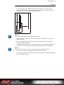
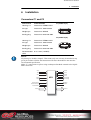
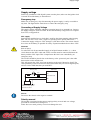
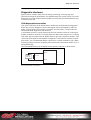
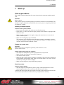
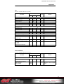
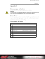
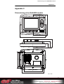
IQAN-MD3
Instruction book
Publ no HY33-8395-IB/UK
Edition 2013-04-24
Contents
1
Introduction . . . . . . . . . . . . . . . . . . . . . . . . . . . . . . . . . . . . . . . . . . . . . . . . . . . . 1
Warnings . . . . . . . . . . . . . . . . . . . . . . . . . . . . . . . . . . . . . . . . . . . . . . . . . . . . 1
Overview of relevant documentation . . . . . . . . . . . . . . . . . . . . . . . . . . . . . . . 2
2
Precautions . . . . . . . . . . . . . . . . . . . . . . . . . . . . . . . . . . . . . . . . . . . . . . . . . . . . 3
Read This . . . . . . . . . . . . . . . . . . . . . . . . . . . . . . . . . . . . . . . . . . . . . . . . . . . . 3
Design of control system . . . . . . . . . . . . . . . . . . . . . . . . . . . . . . . . . . . . . 3
Start-up, maintenance, and diagnostics . . . . . . . . . . . . . . . . . . . . . . . . . 4
3
Product description . . . . . . . . . . . . . . . . . . . . . . . . . . . . . . . . . . . . . . . . . . . . . 5
IQAN-MD3 . . . . . . . . . . . . . . . . . . . . . . . . . . . . . . . . . . . . . . . . . . . . . . . . . . . 5
System overview . . . . . . . . . . . . . . . . . . . . . . . . . . . . . . . . . . . . . . . . . . . 5
I/O overview . . . . . . . . . . . . . . . . . . . . . . . . . . . . . . . . . . . . . . . . . . . . . . 6
CAN related functions . . . . . . . . . . . . . . . . . . . . . . . . . . . . . . . . . . . . . . . . . . 6
Diagnostics . . . . . . . . . . . . . . . . . . . . . . . . . . . . . . . . . . . . . . . . . . . . . . . 7
Communication . . . . . . . . . . . . . . . . . . . . . . . . . . . . . . . . . . . . . . . . . . . . 7
HMI (human machine interface) . . . . . . . . . . . . . . . . . . . . . . . . . . . . . . . . . . . 7
Features . . . . . . . . . . . . . . . . . . . . . . . . . . . . . . . . . . . . . . . . . . . . . . . . . 7
Display . . . . . . . . . . . . . . . . . . . . . . . . . . . . . . . . . . . . . . . . . . . . . . . . . . 8
Environment Specification . . . . . . . . . . . . . . . . . . . . . . . . . . . . . . . . . . . . 8
IQAN-MD3 menu system . . . . . . . . . . . . . . . . . . . . . . . . . . . . . . . . . . . . . . . . 9
Overview . . . . . . . . . . . . . . . . . . . . . . . . . . . . . . . . . . . . . . . . . . . . . . . . . 9
System information . . . . . . . . . . . . . . . . . . . . . . . . . . . . . . . . . . . . . . . . . 9
Preferences . . . . . . . . . . . . . . . . . . . . . . . . . . . . . . . . . . . . . . . . . . . . . . 10
Measuring . . . . . . . . . . . . . . . . . . . . . . . . . . . . . . . . . . . . . . . . . . . . . . . 10
Adjusting . . . . . . . . . . . . . . . . . . . . . . . . . . . . . . . . . . . . . . . . . . . . . . . . 11
Internal Diagnostics . . . . . . . . . . . . . . . . . . . . . . . . . . . . . . . . . . . . . . . . . . . 13
Safe mode . . . . . . . . . . . . . . . . . . . . . . . . . . . . . . . . . . . . . . . . . . . . . . . . . . 13
4
Safety . . . . . . . . . . . . . . . . . . . . . . . . . . . . . . . . . . . . . . . . . . . . . . . . . . . . . . . . 14
Internal diagnostics . . . . . . . . . . . . . . . . . . . . . . . . . . . . . . . . . . . . . . . . . . . 14
CAN-bus interruption . . . . . . . . . . . . . . . . . . . . . . . . . . . . . . . . . . . . . . . . . . 14
Current check . . . . . . . . . . . . . . . . . . . . . . . . . . . . . . . . . . . . . . . . . . . . . . . . 14
Emergency stop . . . . . . . . . . . . . . . . . . . . . . . . . . . . . . . . . . . . . . . . . . . . . . 14
5
Mounting . . . . . . . . . . . . . . . . . . . . . . . . . . . . . . . . . . . . . . . . . . . . . . . . . . . . . 15
Mounting the unit . . . . . . . . . . . . . . . . . . . . . . . . . . . . . . . . . . . . . . . . . . . . . 15
Dashboard or panel assembly . . . . . . . . . . . . . . . . . . . . . . . . . . . . . . . 15
Mounting considerations . . . . . . . . . . . . . . . . . . . . . . . . . . . . . . . . . . . . 15
6
Installation . . . . . . . . . . . . . . . . . . . . . . . . . . . . . . . . . . . . . . . . . . . . . . . . . . . . 17
Connectors C1 and C2 . . . . . . . . . . . . . . . . . . . . . . . . . . . . . . . . . . . . . . . . . 17
Connector pin assignments . . . . . . . . . . . . . . . . . . . . . . . . . . . . . . . . . . . . . 18
Supply voltage . . . . . . . . . . . . . . . . . . . . . . . . . . . . . . . . . . . . . . . . . . . . . . . 19
Emergency stop . . . . . . . . . . . . . . . . . . . . . . . . . . . . . . . . . . . . . . . . . . 19
Connecting of Supply Voltage . . . . . . . . . . . . . . . . . . . . . . . . . . . . . . . . 19
Polarity reversal . . . . . . . . . . . . . . . . . . . . . . . . . . . . . . . . . . . . . . . . . . 19
Addressing . . . . . . . . . . . . . . . . . . . . . . . . . . . . . . . . . . . . . . . . . . . . . . . . . . 20
IQAN-MD3 use of an ID-Tag . . . . . . . . . . . . . . . . . . . . . . . . . . . . . . . . . 20
Diagnostic interfaces . . . . . . . . . . . . . . . . . . . . . . . . . . . . . . . . . . . . . . . . . . 21
CAN diagnostics connection . . . . . . . . . . . . . . . . . . . . . . . . . . . . . . . . . 21
USB connection . . . . . . . . . . . . . . . . . . . . . . . . . . . . . . . . . . . . . . . . . . 22
USB and "ground loops" (differences in ground potential) . . . . . . . . . . 22
Reference voltage, VREF . . . . . . . . . . . . . . . . . . . . . . . . . . . . . . . . . . . . . . . 23
Voltage inputs . . . . . . . . . . . . . . . . . . . . . . . . . . . . . . . . . . . . . . . . . . . . . . . 24
Instruction book, IQAN-MD3
ii
Contents
Connecting sensors to the voltage inputs . . . . . . . . . . . . . . . . . . . . . . . 24
Connecting a 2-wire temperature sensor to voltage in . . . . . . . . . . . . . 25
Connecting switches to the voltage inputs . . . . . . . . . . . . . . . . . . . . . . 25
Connecting switches to the voltage inputs . . . . . . . . . . . . . . . . . . . . . . 26
7
Start-up . . . . . . . . . . . . . . . . . . . . . . . . . . . . . . . . . . . . . . . . . . . . . . . . . . . . . . . 27
Start-up procedures . . . . . . . . . . . . . . . . . . . . . . . . . . . . . . . . . . . . . . . . . . . 27
Starting the control system . . . . . . . . . . . . . . . . . . . . . . . . . . . . . . . . . . 27
Prepare for system start . . . . . . . . . . . . . . . . . . . . . . . . . . . . . . . . . . . . 27
Start the system . . . . . . . . . . . . . . . . . . . . . . . . . . . . . . . . . . . . . . . . . . 27
Appendix A . . . . . . . . . . . . . . . . . . . . . . . . . . . . . . . . . . . . . . . . . . . . . . . . . . . 28
IQAN-MD3 Technical Overview . . . . . . . . . . . . . . . . . . . . . . . . . . . . . . . . . . 28
Absolute Maximum Ratings . . . . . . . . . . . . . . . . . . . . . . . . . . . . . . . . . 28
Environmental ratings . . . . . . . . . . . . . . . . . . . . . . . . . . . . . . . . . . . . . . 28
Recommended Operating Conditions . . . . . . . . . . . . . . . . . . . . . . . . . . 29
System . . . . . . . . . . . . . . . . . . . . . . . . . . . . . . . . . . . . . . . . . . . . . . . . . 29
I/O . . . . . . . . . . . . . . . . . . . . . . . . . . . . . . . . . . . . . . . . . . . . . . . . . . . . . 30
User interface . . . . . . . . . . . . . . . . . . . . . . . . . . . . . . . . . . . . . . . . . . . . 30
Appendix B . . . . . . . . . . . . . . . . . . . . . . . . . . . . . . . . . . . . . . . . . . . . . . . . . . . 31
Error messages and actions . . . . . . . . . . . . . . . . . . . . . . . . . . . . . . . . . . . . . 31
Failure Modes . . . . . . . . . . . . . . . . . . . . . . . . . . . . . . . . . . . . . . . . . . . . . . . . 31
Failure modes for CAN interface . . . . . . . . . . . . . . . . . . . . . . . . . . . . . . 31
Failure modes for VREF . . . . . . . . . . . . . . . . . . . . . . . . . . . . . . . . . . . . 32
Failure modes for VIN . . . . . . . . . . . . . . . . . . . . . . . . . . . . . . . . . . . . . . 32
Failure modes for DIN . . . . . . . . . . . . . . . . . . . . . . . . . . . . . . . . . . . . . . 32
Appendix C . . . . . . . . . . . . . . . . . . . . . . . . . . . . . . . . . . . . . . . . . . . . . . . . . . . 33
Dimensioning of the IQAN-MD3 module . . . . . . . . . . . . . . . . . . . . . . . . . . . 33
Instruction book, IQAN-MD3
iii
Warnings
1
1
Introduction
Introduction
These instructions are to be used as a reference tool for the vehicle manufacturer’s
design, production, and service personnel.
The user of these instructions should have basic knowledge in the handling of
electronic equipment.
Warnings
Sections marked with a symbol in the left margin, must be read and understood by
everyone using the system, carrying out service work, or making changes to hardware
and software.
The different symbols used in this manual are defined below.
WARNING
Sections labeled WARNING with a caution symbol in the left margin, indicate that a
hazardous situation exists. We use warnings, marked with the warning symbol, in two
ways.
• As a strong recommendation about work practices when using the product in the
machine (e.g. routines when updating an application). This use is common to the
term 'hazardous situation', that a person is exposed to a hazard.
• As a way of pointing out important information for the machine designer that in
some way relates to safety. This includes the design of the physical machine, and
also the application program being developed for the control system.
Not all document sections that contain information about safety are marked with a
warning symbol (there would be warnings everywhere). Failure to comply with the
recommendations can cause unintentional, and unexpected behavior of the control
system. This can potentially cause death, serious injury or property damage.
N OTICE
Sections labeled NOTICE with a notice symbol in the left margin, indicate there is
important information about the product. Ignoring this could result in less than optimal
performance, or damage to the product.
Contact the manufacturer if there is anything you are not sure about or if you have any
questions regarding the product and its handling or maintenance.
The term "manufacturer" refers to Parker Hannifin Corporation.
1
Instruction book, IQAN
Overview of relevant documentation
1
Introduction
Overview of relevant documentation
The following publications are relevant for users of this product.
The main documentation contains information that is not found elsewhere.
The additional documentation contains product information in a compact format, for
details on the information found in those documents, consult this manual.
Main
Documentation
Compact
Documentation
IQANdesign/
IQANrun
User Manuals
IQAN module
Instruction Book
HY33-8nnn-IB
IQAN module
Catalogue Datasheet
HY33-8nnn
Mounting and Maintenance
Instruction Book
HY33-8327-IB
IQAN module
Installation Sheet
HY33-8nnn-IS
IQAN module
Electrical Schematic
HY33-8nnn-ES
The IQAN module documentation system.
2
Instruction book, IQAN
Read This
2
2
Precautions
Precautions
Work on the hydraulics control electronics may only be carried out by trained
personnel who are well-acquainted with the control system, the machine and its safety
regulations.
WARNING
Make sure that you have sufficient knowledge before designing, modifiying or
servicing the control system.
Read the relevant sections of this document before conducting any work on the control
system.
WARNING
This product is not field repairable.
N OTICE
As much as possible of the welding work on the chassis should be done before the
installation of the system. If welding has to be done afterwards, the electrical
connections on the system must be disconnected from other equipment. The negative
cable must always be disconnected from the battery before disconnecting the positive
cable. The ground wire of the welder shall be positioned as close as possible to the
place of the welding. The cables on the welding unit shall never be placed near the
electrical wires of the control system.
Read This
Design of control system
WARNING
Risk of injury may be introduced by design of control system!
This product is designed to control hydraulic outputs. The control application must be
designed using basic safety principles so that unintentional movement is avoided.
The machine must be equipped with an emergency stop that stops all movement. Please
refer to section "Supply voltage".
Before you start
Read this document.
Read the IQANdesign software user manual section on 'application safety'.
3
Instruction book, IQAN
Read This
2
Precautions
Start-up, maintenance, and diagnostics
For all personnel carrying out installation, commissioning, maintenance or
troubleshooting.
WARNING
Work on the hydraulics control electronics may only be carried out by trained
personnel who are well-acquainted with the control system, the machine and its safety
regulations.
Before you start,
Read section "Start-up".
Additional information for service
Mounting and maintenance instruction book.
Additional information for diagnosing the system
Read section "System diagnostics", and see "Appendix B", in this document.
Use the IQANrun software user manual as a reference.
4
Instruction book, IQAN
IQAN-MD3
3
3
Product description
Product description
IQAN-MD3
IQAN-MD3 is a combined display and bus master capable of running applications
created by IQANdesign. Built on a 32-bit platform the unit has large computational
power and is capable of controlling large applications.
The IQAN-MD3 module.
System overview
The master module, IQAN-MD3, is the central unit in the system, or in the case of a
multi-master system, one of the central units. IQAN-MD3 has three CAN buses. The
CAN buses support ICP and are able to control IQAN expansion units. SAE J1939 and
Generic CAN protocols are also supported on the CAN buses and gives the possibility
to interface to 3rd party units. It is recommended to keep one CAN bus available (no
traffic or minimal traffic) for diagnostic purposes.
"Soft" function buttons and control buttons in combination with a graphical display
makes system feedback with user interaction possible. The display in the module has
very high optical performance across a wide operating temperature range and over a
wide range of ambient light.
IQAN-MD3 has voltage and digital inputs that are designed to be flexibly configured
using IQANdesign software. The unit also has a low power digital output.
All I/O are EMI filtered and protected against short circuit to -BAT and +BAT.
Levers and sensors
IQAN-MD3
Expansion units
A typical IQAN-MD3 system
5
Instruction book, IQAN- MD3
CAN related functions
3
Product description
I/O overview
+BAT
CAN-H
-BAT
CAN-L
+RTC
CAN-H
CAN-L
+VREF
-VREF
MD3
CAN-H/Diag
CAN-L/Diag
RS232-DATA IN
USB-D+
RS232-DATA OUT
USB-D-
RS232-READY
PORT 1
PORT 0
Inputs/Outputs
The IQAN-MD3 module has seven (7) voltage inputs VIN-A thru VIN-G for
connection of 0-5 Vdc signals. These inputs can be configured as digital inputs for
reading switches. Voltage inputs and digital inputs share positions, see below.
(7) Voltage inputs VIN-A, VIN-B, VIN-C, VIN-D.....VIN-G
or
(7) Digital inputs DIN-A, DIN-B, DIN-C, DIN-D...... DIN-G
There is a digital output, DOUT-A, on IQAN-MD3 that may be activated when there is
an error message for the system, such as a short-circuit and input or output interruption.
By connecting the digital output to a warning lamp or audio signal, the driver is alerted
that an error message has been given.
Connect the alarm (audio signal) between pin C2:12 and ground (the battery’s negative
pole). See the illustration below. An active output gives battery voltage (11-32 Vdc) to
the pin. The maximum load is 200 mA.
IQAN-MD3
DOUT
Connection of DOUT as an alarm output.
CAN related functions
The IQAN-MD3 uses three CAN-buses (CAN = Controller Area Network) to
communicate with IQAN expansion modules, other systems and diagnostics.
6
Instruction book, IQAN- MD3
HMI (human machine interface)
3
Product description
Diagnostics
Any of the IQAN-MD3 CAN buses may be dedicated for diagnostic purposes. This
function is available when using IQANdesign 2.0 version or higher.
N OTICE
It is recommended to have one CAN bus dedicated for diagnostic purposes.
Communication
The IQAN-MD3 has one RS232 port for remote diagnostics via ’dial-up’ modem
communication and one USB port for connection with a PC.
HMI (human machine interface)
IQAN-MD3 front panel HMI.
Features
IQAN-MD3 has a 3.5" transflective TFT color display, 320x240 pixels for reading
system information. The front of IQAN-MD3 consists of a control panel with a display
and nine buttons.
• F1 thru F4 function buttons.
Programmable ’softkeys’ that can be configured by IQANdesign software to bring
up a display page, bring up an adjustment group or act as a virtual input.
• Up and down arrow buttons
,
.
Navigation buttons that are used to scroll thru selections on a menu page. May be
configured by IQANdesign software to bring up a display page, bring up an
adjustment group or act as a virtual input.
• OK button
.
Pushing this button equals ’enter’. Saves the value or confirms the selection you
have made.
• Menu button
.
Always brings up the Menu page. It is not programmable.
• ’Esc’ or BACK button .
Returns you to the previous display page. May be configured by IQANdesign
software to bring up a display page, bring up an adjustment group or act as a virtual
input.
7
Instruction book, IQAN- MD3
HMI (human machine interface)
3
Product description
Display
Brightness
The brightness is easily adjusted by pressing the ’menu’ button and following the
prompts to the backlight settings section.
Burn-in
The IQAN-MD3 TFT display, like other computer screens can have a ghost picture
occur if a static image is left on the display for extended periods of time. For the best
viewing over the life of the product we recommend using the screensaver functionality.
N OTICE
To avoid burn-in, use the screensaver on the display.
Maintenance
The 3.5" transflective display is a high quality viewing interface and reasonable care
should be taken to maintain it.
The display can be cleaned with an LCD cleaning solution found in many stores. Use a
lightly dampened lint-free, non-abrasive cloth when cleaning the display.
N OTICE
To avoid scratches, do not wipe or clean a dry display.
Polarization
The MD3 screen has polarizers, the TFT is defined by its manufacturer as portrait
mode, but we have tilted it to have a landscape mode display. When wearing polarized
sunglasses, the effect is for the screen to be unreadable due to the conflicting
polarizations. This is easily solved by applying a film to the display. One type of film
that is proven to work is NuShield DayVue anti-reflective overlay film.
Environment Specification
IQAN-MD3 is a hardened module suitable for outdoor use. However, concentrating
cleaning jets on the control surface of the IQAN-MD3 can cause a degradation of the
finishing and should be avoided.
N OTICE
To keep the unit’s buttons looking their best, do not blast the control surface with
cleaning jets.
Back of unit
If the rear surface of the IQAN-MD3 unit is exposed and will be subjected to high
pressure steam cleaning, care should be taken around the connector assemblies. The
Deutsch DTM connectors are IP67 rated which is suitable for any type of outdoor
conditions. However, concentrating the cleaning jets on the connectors of the IQANMD3 can cause damage to the connector seals or wire insulation and should be
avoided. Use of shielding is recommended to block high pressure cleaning jets, if the
rear of the unit is exposed.
N OTICE
To avoid damaging the connector seals or wire insulation, do not blast the connectors
with cleaning jets.
8
Instruction book, IQAN- MD3
IQAN-MD3 menu system
3
Product description
IQAN-MD3 menu system
The IQAN-MD3 has an easy to use graphical user interface and menu system. In the
display’s menu system, you get access to information and settings concerning the
IQAN system.
Operating
display page
From any page:
Press menu to quit or
press escape to go back
to the previous page
Press menu button
Menu page
Press a function button
Adjustment
page
Measurement
page
Preferences
page
Information
page
Select
adjust group
Select
measure group
Select
display, time
or language
Select
module,
modem or log
Select function
or channel
Select raw or
scaled value
Change
settings
View
information
Change
parameters or
reset to defaults
View
measurements
Menu navigation flowchart.
Overview
The menu system is an easy to use set of pages in the IQAN-MD3 that allow you to see
module information and logs, set preferences, measure system I/O or adjust
parameters.
All of this is done using the control and function buttons on the face of the IQANMD3. To begin, go to the main menu page by simply pressing the ’menu’ button (three
horizontal lines). You may return to the operating display at any time by pressing the
menu button again.
Main
Adjust
Measure Preferences
Info
menu button
Main menu page.
System information
To see information about your system press the button on the main menu page under
the ’Info’ icon, F4. This will bring up the information page which displays the loaded
application name, the last person who performed an edit and when the edit was done.
9
Instruction book, IQAN- MD3
IQAN-MD3 menu system
3
Product description
Other button options now appear for the function buttons that allow you to view
information about modules, modem or logs. To return to the previous (main menu)
page you can press the ’escape’ button. The ’escape’ button always takes you back to
the previous page. If you have chosen to view information on any of the other pages
you are given the option to simply press the button under the ’Main’ icon, F1.
Main
Measure Preferences
Adjust
Info
esc button
to go back
Information page.
Preferences
To set preferences for the IQAN-MD3 press the button on the main menu page under
the ’Preferences’ icon, F3. This will bring up the preferences page. Other button
options now appear for the function buttons that allow you to set preferences for the
display, date/time or language. To return to the previous (main menu) page you can
press the ’escape’ button. If you have chosen to view information on any of the other
pages you are given the option to simply press the button under the ’Main’ icon, F1.
Main
Adjust
Measure Preferences
Info
esc button
to go back
Preferences page.
Measuring
If you would like to measure any channels using the IQAN-MD3 press the button on
the main menu page under the ’Measure’ icon, F2. This will bring up the measure page
that displays the measure groups that have been set up in IQANdesign. To select a
measure group you press the up or down buttons until it is highlighted and then press
’OK’. That takes you to a page where you may view the channels in the selected group.
Button F2 may now be used to toggle between raw values and scaled values for the
channels. To return to the measure page you can press the ’escape’ button. To return to
the main menu page, you are given the option to simply press the button under the
’Main’ icon, F1.
10
Instruction book, IQAN- MD3
IQAN-MD3 menu system
3
Product description
Main
press OK
to select
Measure Preferences
Adjust
Info
Measure page.
Adjusting
If you would like to adjust any channels using the IQAN-MD3 press the button on the
main menu page under the ’Adjust’ icon, F1. This will bring up the adjust page that
displays the adjustable groups that have been set up in IQANdesign. To select an
adjustable group you press the up or down buttons until it is highlighted and then press
’OK’. That will take you to the next page, where you may view the channels in the
selected group. If a lock icon,
is next to the group in the list, then a pin code is
required to access that group. Press the up, down and OK buttons to enter the pin code
lock icon
Main
press OK
to select
Adjust
Measure Preferences
Info
Adjust page.
Once you have selected a group, a list of the adjustable channels is displayed. You may
select a particular channel in the same way you selected the group, by using the up and
down buttons and pressing OK. To choose the plus or minus direction for adjusting, use
the appropriate function button F3 or F4. The current parameters for the highlighted
direction are displayed on the right side of the display window. When you have
highlighted the desired channel and direction, press OK.
11
Instruction book, IQAN- MD3
IQAN-MD3 menu system
3
Product description
Main
press OK
to select
Measure Preferences
Adjust
Info
Adjust group page.
Adjusting a parameter
Now you are at the page where the actual adjustment is done. You may toggle through
the different parameters by pressing OK repeatedly. When the parameter you wish to
adjust is highlighted, you may change it by pressing the up and down buttons. The
displayed values change to give you feedback. At any time after adjustments have been
made, if you want to return to the default values of the application, you may press the
button under the ’Reset’ icon, F2. To return to the previous page you can press the
’escape’ button. To return to the main menu page, you are given the option to simply
press the button under the ’Main’ icon, F1.
Main
press up and
down to adjust
Adjust
Measure Preferences
Info
Adjusting a parameter.
12
Instruction book, IQAN- MD3
Internal Diagnostics
3
Product description
Internal Diagnostics
The IQAN-MD3 has a diagnostics page. This page can be useful for obtaining
diagnostic information. To view the test page, press the menu and escape buttons
simultaneously and hold during power up. To exit test mode, turn the unit off and
power up normally.
menu button
esc button
Accessing the diagnostics page.
Safe mode
If necessary, the IQAN-MD3 may be started in safe mode. When started in safe mode,
no application is loaded and nothing is running. The screen shows a default background
and a dialog box notifies the user that the unit is in safe mode. This can be useful for
installing an IQAN-MD3 with an unknown application in memory, when retrofitting of
new hydraulic components has occurred or if a user has somehow changed the
application in an unacceptable way. To start in safe mode, press the escape button and
hold during power up. In safe mode you can then upload a new application to the
IQAN-MD3. To exit safe mode, turn the unit off and power up normally.
13
Instruction book, IQAN- MD3
Internal diagnostics
4
4
Safety
Safety
Internal diagnostics
The module performs a number of self-checks that improve safety. Checks include
monitoring of voltage supplies, checksums on memory and a watchdog that monitors
software execution. The module is using a real time operating system which supervises
software execution.
If a critical error is detected, the module is stopped, with CAN-bus and outputs off.
CAN-bus interruption
The IQAN modules communicate on a CAN-bus. Both the master module and
expansion modules check for any interruptions in CAN-bus communication. If an error
occurs the master will use zero or an application defined error value for the module
inputs, and the module outputs will be off.
The error will be presented on the master/display module, if there is one, and with a
related blink code on the IQAN module status LEDs.
Current check
For the proportional outputs when used in current mode, a current check is performed.
If an error is detected, this will be indicated on the master module, and the output will
shut off.
The module can detect open-circuit, short-circuit to +BAT/-BAT or short-circuit to
other proportional output and return pins.
Emergency stop
WARNING
Risk of injury!
The emergency stop must disconnect the power supply to the module; do not connect
the emergency stop as a signal input only.
The emergency stop must be installed so that the risk of reverse feed of the module is
avoided, see section "Supply voltage".
8
Instruction book, IQAN
Mounting the unit
5
5
Mounting
Mounting
Mounting the unit
The IQAN-MD3 unit should be mounted according to the following instructions.
Dashboard or panel assembly
• When installing in a dash or panel the recommended panel thickness is 1.0 - 3.5
mm. Use PT40 screws to mount the unit
Mv-0.8-1.0 Nm
PT40 screw
91
82
R8.0 max
96
11
8
ø4.5
Mounting the IQAN-MD3.
N OTICE
Select the screw length so that the thread engagement in the unit is 8-11 mm.
• Less engagement and the screw may not hold.
• More engagement and the housing may be damaged.
Mounting considerations
N OTICE
IQAN-MD3 shall be positioned in the machine per the following instructions:
• The unit is designed for outdoor use. Position the unit in desired location and make
sure that it is not exposed to mechanical damage.
• The connectors on the reverse side of the unit should be accessible.
• Position the unit so there is no risk that the cabling can be folded, crushed, worn or
damaged in any way.
15
Instruction book, IQAN- MD3
Mounting the unit
5
Mounting
• Leave sufficient room behind the unit to insert connectors. Less than 75 mm
clearance will stress the cabling and distort the seals in the connectors. This can
cause the environmental specification not to be met.
75 mm
22 mm
48 mm
Distance behind the unit.
N OTICE
Take careful consideration when positioning the unit.
• Position the unit so there is no risk to be exposed to external heat, e.g. from the
engine or heater.
• The best readability will be achieved by positioning the front face of the unit
directly towards the operator.
• Extended periods of exposure to direct sunlight can cause an internal temperature
exceeding 75°C which may cause permanent degradation of the LCD display.
N OTICE
Both of the connectors, C1 and C2, must be properly installed in the unit.
• If you leave a connector unplugged, the unit will not be sealed.
• If unused wire positions in a connector are not closed with the recommended plugs,
the unit will not be sealed.
16
Instruction book, IQAN- MD3
Connectors C1 and C2
6
6
Installation
Installation
Connectors C1 and C2
Connector kit
Parker 20073081
C1 (DTM12 key A)
Housing, C1
Deutsch no. DTM06-12-SA
Pin type
Deutsch no. 1062-20-0222
Wedge type
Deutsch no. WM12S
Sealing plug
Deutsch no. 0413-204-2005
1 2 3 4
12 11 10 9
5
8
6
7
C2 (DTM12 key B)
Housing, C2
Deutsch no. DTM06-12-SB
Pin type
Deutsch no. 1062-20-0222
Wedge type
Deutsch no. WM12S
Sealing plug
Deutsch no. 0413-204-2005
Recommended
cable
0.75-1 mm2 (18 AWG)
1 2 3
12 11 10
4
9
5
8
6
7
N OTICE
No pin may be "double crimped". That means only one wire may be attached to any
given pin. Failure to follow this instruction will cause the module to not meet the
environmental specification.
Make "Y" connections or splices using weatherproof methods external to the IQANMD3 connectors.
+BAT
CAN-H
-BAT
CAN-L
+RTC
CAN-H
CAN-L
+VREF
-VREF
MD3
CAN-H/Diag
CAN-L/Diag
RS232-DATA IN
USB-D+
RS232-DATA OUT
USB-D-
RS232-READY
PORT 0
PORT 1
17
Instruction book, IQAN- MD3
Connector pin assignments
6
Installation
Connector pin assignments
Symbol
Pin
No.
Input
Output
Function
+BAT
C1:12
-
Power supply
-BAT
C1:1
-
Power supply
+RTC
C1:7
-
Power supply for RTC.
+VREF
C2:8
-
Voltage reference for external sensors. Sourcing +5V.
-VREF
C2:5
-
Voltage reference for external sensors. Return (0V).
ADDR-L
C1:6
-
Address lowpin for IDtag. For multi-master systems.
CAN-A-L
C1:2
-
CAN low voltage bus line.
CAN-A-H
C1:11
-
CAN high voltage bus line.
CAN-B-L
C1:3
-
CAN low voltage bus line.
CAN-B-H
C1:10
-
CAN high voltage bus line.
CAN-C-L
C1:4
-
CAN low voltage bus line for diagnostics.
CAN-C-H
C1:9
-
CAN high voltage bus line for diagnostics.
RS232-TD
C1:8
O
RS232 data out
RS232-RD
C1:5
I
RS232 data in
USB-D-
C2:6
-
USB low voltage bus line.
USB gnd connects to -VREF. USB shield may only be
connected on PC side.
USB-D+
C2:7
-
USB high voltage bus line.
USB gnd connects to -VREF. USB shield may only be
connected on PC side.
P0
P0.0
P0.1
P0.2
P0.3
P0.4
P0.5
P0.6
P0 is a 7 input port with alternative functions.
C2:1
C2:2
C2:3
C2:4
C2:9
C2:10
C2:11
I
I
I
I
I
I
I
P1
P1.0
VIN
VIN-A
VIN-B
VIN-C
VIN-D
VIN-E
VIN-F
VIN-G
DIN
DIN-A
DIN-B
DIN-C
DIN-D
DIN-E
DIN-F
DIN-G
P1 is a 1 output port.
C2:12
O
DOUT
DOUT-A
18
Instruction book, IQAN- MD3
Supply voltage
Supply voltage
Before any installation of the IQAN system can take place, make sure the ignition lock
is turned off and the battery is disconnected.
Emergency stop
Make sure an Emergency Stop disconnecting the power supply, is easily accessible at
any time. The figure below shows how to connect the emergency stop.
Connecting of Supply Voltage
The supply voltage, should be within the operating interval, see Appendix A. Connect
the supply voltage to +BAT and -BAT. Protect the module by using a fuse. For requisite
fuse level, see Appendix A.
RTC supply
IQAN master modules have a clock that is used for date/time stamping when logging
data. The real time clock, +RTC, requires a separate positive power connection.
Connect the supply voltage to +RTC through a 1.5K ohm resistor. The resistor should
be as close to the battery as possible for safety. Expansion modules do not have +RTC.
WARNING
Risk of injury!
To reduce the risk for uncontrolled supply of an IQAN master module, i.e., a short
circuit between the +RTC cable and +BAT, a resistor must be connected between the
battery and the +RTC input. This is important as this line is not controlled by an
emergency stop.
The resistor should be placed close to the battery, as the ’protected’ part is the cable
between the resistor and the unit.
This will prevent the +RTC wire from powering up the unit if shorted to +BAT. The
same possibility exists from a short to CRET wires when they are used as digital inputs;
refer to section "DIN that share pin with RET".
IQAN module
Emergency Stop
Fuse
*
+BAT
+RTC (if master unit)
1.5 k
-BAT
+
-
* Symbol for disconnecting
switch for battery, ignition
lock and other fuses.
Connecting the emergency stop and voltage supply.
N OTICE
Do not use the chassis as the negative terminal.
Polarity reversal
The module is protected against power supply polarity reversal and over-voltage,
provided an external fuse is being used.
If this fuse is not used, polarity reversal can damage the unit.
12
Instruction book, IQAN
Addressing
Addressing
IQAN-MD3 use of an ID-Tag
In IQANdesign 3.0 and higher software, more than one IQAN master module can be
used together in a multi-master system. The master modules are each given a unique
address by using an ID-Tag. The value of the ID-Tag identifies the master and will
enable a single project application to be loaded into more than one master module over
the CAN bus. The functionality needed for each master is loaded based on the ID-tag
address. By default, if no ID-tag is installed, the MD3 will be address 0.
Identification of an IQAN-MD3 by address
For normal operation of an IQAN-MD3 in a single master system, the ID-Tag is not
used. It is only needed when the IQAN-MD3 is used in a multi-master system, and an
address other than ’0’ is needed. The connection of an ID-Tag between +VREF and
ADDR-L will assign an address to the IQAN-MD3 master module. The desired
functionality based on address is built into the project file using IQANdesign software.
For more information, please refer to the IQANdesign user manual.
It is the combination of address and type that gives each master module a unique
identification.
EXAMPLE
If having an IQAN-MD3 master module with an ID-Tag of address 3, the system
will recognize an address value of 3 to the application. You could have one MD3-0,
one MD3-3 and one MC3-1 (or some other combination of master units) in the same
multi-master system.
The maximum number of MD3 addresses is 6, denoted as addresses 0, 3, 4, 5, 6, 7
respectively.
N OTICE
Addresses 1 and 2 are reserved and can not be used for addressing an IQAN-MD3.
In order to assign any IQAN-MD3 a unique address, an ID-Tag will have to be
connected to the positions +VREF and ADDR-L.
IQAN-MD3
+VREF
ADDR-L
ID-Tag
Connecting of Id-Tag.
20
Instruction book, IQAN- MD3
Diagnostic interfaces
Diagnostic interfaces
IQAN software includes many tools for tuning, measuring, accessing logs and
otherwise checking the performance or troubleshooting your control system. To use the
diagnostic tools with an IQAN master module you may choose between different ways
to connect to the unit.
CAN diagnostics connection
One of the CAN buses of the IQAN master module may be dedicated for diagnostics.
Reserving a bus for diagnostics ensures that signals are not interrupted by other bus
traffic. A high-speed CAN interface is needed to use this feature. Contact Parker for
information about supported CAN interfaces.
A termination resistor is usually required at the CAN interface on the PC. Parker part
number 5030082 or 5030182, or an equivalent 120 ohm resistor may be used. A flying
lead cable may be connected to the IQAN master to provide a connector interface. The
connection from IQAN master module to diagnostic CAN interface can then be made
quite easily. It is recommended that the connector be a sealed, automotive type. When
not being used this connector should be protected from the environment with a cover or
mating blank plug.
The recommended wiring to the IQAN master module connector is shown below.
IQAN master
CAN-X-H
Customer
provided
connector
120 ohm
CAN-X-L
Connecting for CAN communication.
15
Instruction book, IQAN
USB connection
This IQAN master module has an USB interface for communicating with the
programming software, IQANdesign and for diagnostics. A flying lead cable, 5030124
may be connected to the master module to provide an USB type B connector interface.
The connection from the module to PC can be made with a standard USB Type A male
to Type B male cable.
Connection of Parker cable 5030124 is shown below.
IQAN master
-VREF
DATADATA+
USB type B port
Connecting for USB communication.
N OTICE
It is recommended that the two data wires, DATA+ and DATA-, be a twisted pair, 15
twists/meter. Use -VREF for the ground connection as shown.
USB and "ground loops" (differences in ground potential)
When systems consisting of machines, modules, computers and other devices with
different ground potentials are connected by a USB cable, a ground loop may be
created. The grounds may only differ by a few millivolts, or by much more. This can be
significant when compared to the low level voltage signals that are used in USB data
transmission.
N OTICE
Protect the PC and unit from damage due to ground loops and surges!
Ground loops can cause problems in communicating and in extreme cases the amount
of current flow can damage the USB transceiver in the PC or the module.
A recommended way to prevent ground loops is to ensure that your system includes
isolation. Isolation protects your PC from damage and preserves the integrity of your
data by physically separating the electrical connections between the PC and the unit.
Good: Using a battery-powered laptop can prevent the formation of accidental ground
loops and short circuits. This protection only holds true, however, as long as the laptop
is not also connected to self-powered devices such as printers.
Better: Isolation can be provided by adding an isolated USB hub between the PC and
the unit.
Best: Use a CAN-USB interface with galvanic isolation and communicate with unit via
CAN bus. This setup is used in the automotive industry for diagnostics.
16
Instruction book, IQAN
Reference voltage, VREF
Reference voltage, VREF
The IQAN module is internally equipped with a voltage regulator to generate the
reference voltage VREF. The standard reference voltage will feed different kinds of
sensors and potentiometers.
IQAN module
+VREF
-VREF
VREF positions.
N OTICE
It is strongly recommended to use the module’s -VREF and +VREF to all sensors and
potentiometers that are connected to the module inputs. This will reduce bad
measurement based on potential fault (i.e. different ground points for other supplies in
relation to the IQAN module ground, -BAT).
Maximum load for the VREF is different according to 12/24 Vdc power supply, see
"Appendix A".
17
Instruction book, IQAN
Voltage inputs
Voltage inputs
Connecting sensors to the voltage inputs
The sensor signal range must be 0-5 Vdc. To detect signal errors such as short circuits
or interruptions the active signal range be within 0.5-4.5 Vdc.
[V]
5
Error detection range
Active signal range
Error detection range
0
t
Active signal range.
The current consumption related to the voltage input is negligible.
The positive terminal of the sensor is connected to the +VREF position and the
corresponding negative terminal to the -VREF position. The sensor signal is connected
to appropriate VIN position.
EXAMPLE
Connect the positive and negative terminals of the position sensor to +VREF,
and -VREF, respectively. Then connect the sensor signal to VIN-X.
IQAN module
+VREF
VIN-X
-VREF
Position Sensor
Connecting VREF and sensor signal VIN-X.
N OTICE
The negative terminal of the sensor must not be connected to the chassis.
Maximum load for VREF position: see Appendix A.
Connecting other 3 wire sensors
The same type of connection shown for potentiometers is used for other 3 wire sensors
supplied with power from the regulated 5VDC supply, VREF. This includes active
temperature sensor IQAN-ST, pressure sensor IQAN-SP and Hall-effect levers IQANLST or IQAN-LSL.
18
Instruction book, IQAN
Voltage inputs
Connecting a 2-wire temperature sensor to voltage in
When you connect a PTC (positive temperature coefficient) temperature sensor you
may need to use a pull up resistor on the input signal. Please check the technical data
for your specific temperature sensor.
EXAMPLE
Connect the negative terminal of the temperature sensor to -VREF, and the signal to
VIN-X. The pull up resistor will be connected between VIN-X, and +VREF.
IQAN module
+VREF
pull up
VIN-X
-VREF
Sensor
Connecting -VREF and temperature sensor signal VIN-X.
The pull up resistor value for a R25=2000Ω, PTC sensor is 4,7 KΩ.
Connecting switches to the voltage inputs
Switches could be connected to the voltage inputs, to create a digital on/off signal. The
switches should be connected to +VREF and VIN/DIN respectively for 5V signal. The
current consumption for the input is negligible.
EXAMPLE
Connect the positive and negative terminals of the switch to +VREF, and VIN-X,
respectively.
IQAN module
+VREF
VIN/DIN-X
switch
Connecting a switch to VIN-X and VREF.
N OTICE
Maximum load for VREF position, see "Appendix A".
19
Instruction book, IQAN
Voltage inputs
Connecting switches to the voltage inputs
It is recommended to connect system voltage +BAT to the input through a switch in
order to reserve 5Vdc VREF for sensors and potentiometers.
EXAMPLE
Connect the positive and negative terminals of the switch to supply or the unit’s
+BAT, and DIN-X, respectively.
+BAT
IQAN module
DIN-X
switch
Connecting a switch to DIN-X and +BAT.
20
Instruction book, IQAN
Start-up procedures
7
7
Start-up
Start-up
Start-up procedures
This chapter contains instructions for action to be taken in connection with the initial
start.
WARNING
Risk of injury!
If the control system is not fitted properly, the machine could move uncontrollably. The
machine’s engine shall not be started before the control system is completely fitted and
its signals are verified.
Starting the control system
Start the control system as follows:
• Prior to start, all modules and cables are to be fitted correctly.
• Check fuses, i.e. make sure that the supply voltage to the modules is equipped with
the correct fuse.
• Make sure that connections for supply voltage and return lines are correct in the
cable’s conductor joint.
• Make sure an emergency stop is installed.
The emergency stop should disconnect the supply voltage to all modules. Alternatively, the emergency stop may also shut off the diesel engine or a dump valve, and
with that, depressurize the hydraulic system.
Prepare for system start
WARNING
Make sure no one is in dangerous proximity to the vehicle to avoid
injuries when it starts.
Prepare for the initial system start as follows:
•
•
•
•
The engine for the hydraulic system’s pump shall be in off position.
Make sure that all connectors are properly connected.
Turn on the control system.
Make sure that voltage is being supplied to all modules; the power/status diode shall
be illuminated on all modules. Also, make sure that the master is in contact with all
modules by reading the master’s display.
• Make sure the emergency stop is functioning properly.
Start the system
Start the system as follows:
• Start the engine for the hydraulic system’s pump, assuming that the above mentioned inspections have been carried out and shown correct values.
Calibrate and adjust input and output signals according to the instructions related to the
master menu system and check each and every output function carefully.
27
Instruction book, IQAN
IQAN-MD3 Technical Overview
Appendix A
Appendix A
IQAN-MD3 Technical Overview
Absolute Maximum Ratings1
Limit values
Parameter
Unit
min.
typ.
Remark
max.
Ambient temperature, TA
Storage temperature
– 30
– 30
+60
+75
°C
Voltage supply on +BAT
6
34
V
Reverse polarity protected
34
V
Max voltage on USB
signals D+ and D- is 3.5V.
Voltage on any pin with
respect to -BAT
1.The “Absolute Maximum Ratings” table lists the maximum limits to which the device can be subjected without damage. This doesn´t imply that the device will function at these extreme conditions,
only that, when these conditions are removed and the device operated within the “Recommended
Operating Conditions”, it will still be functional and its useful life won’t have been shortened.
Environmental ratings
Limit values
Parameter
Unit
min.
EMI
ISO 14982:1998
EN 55025:2003
ISO 11452-2:1995
ISO 11452-4:2001
ISO 7637-3:1995
ISO 7637-2:1990
typ.
Remark
max.
MHz
MHz
V/m
mA
V
V
30-3000 MHz
0.15-108 MHz
20-1000 MHz
1-200 MHz
25
8
8
kV
air
contact
handling
Mechanical environment
IEC 60068-2-64:1993 Fh
IEC 60068-2-29:1987 Eb
0.4
40
g2/Hz
g
15- 250 Hz, 10 hours
6 ms
Climate environment
IEC 60529:2001 IP66
DIN 40050 Part 9:1993 IP6K9K
IEC 60068-2-30:1985 Db
IEC 60068-2-78:2001
IEC 60068-2-2:1993-01 Bb
IEC 60068-2-1:1993-02 Ab
IEC 60068-2-14:1984 Nb
3
30
6
21
72
16
10 x 6
min
sec
cycles
days
hour
hour
hour
100 l/min
1000kPa, +80°C
+55°C, 95% RH
44°C, 93% RH
70°C
-40°C
-40°C to 70°C
Chemical environment
IEC 60068-2-52:1996 Kb
3
days
ESD
ISO 10605:2001
100
150
80
1a,2,3a,3b,4,5
28
Instruction book, IQAN-MD3
IQAN-MD3 Technical Overview
Appendix A
Recommended Operating Conditions1
Limit values
Parameter
Unit
min.
typ.
Remark
max.
Ambient temperature, TA
– 30
+60
°C
Voltage supply, VBAT
11
32
V
When the unit detects an
internal temperature that
exceeds -25°C to +75°C the
LCD will be turned off to
reduce the risk for permanent
damage of the LCD. When
turned off the backlight will be
used as an indicator with a
heart-beat:
When the temperature normalizes (within -20°C to
+70°C) the LCD will be turned
on automatically.
1.Recommended operating conditions are given for maximum and minimum conditions where normal performance is still available from the device. Once the normal operating conditions are exceeded, the performance of the device may suffer.
System
TA = +25 °C (unless otherwise specified)
Limit values
Parameter
Unit
min.
Start-up delay
typ.
Remark
max.
350
ms
Power to activated output
System cycle time, Tsc
10
100
ms
Sample rate local I/O
10
100
ms
System cycle time
Output voltage on VREF
4.95
When load < 50mA
5.05
V
Load current on VREF
150
mA
Current supply
VBAT =14V
VBAT =28V
190
130
mA
outputs = off
no load on VREF
Current supply RTC
+RTC =14V
+RTC =28V
4
8
mA
Same supply current for
VBAT=0V or VBAT > 11V
RTC power backup
Weight
2
5.00
14
days
270
g
29
Instruction book, IQAN-MD3
IQAN-MD3 Technical Overview
Appendix A
I/O
TA = +25 °C (unless otherwise specified)
Limit values
Parameter
Unit
min.
typ.
Remark
max.
VIN (Voltage input)
Signal range low
Signal range high
0
4.95
0.05
5.00
V
V
Input resistance
36
kΩ
Signal resolution
1.2
mV
Relative accuracy1
10
mV
1.0
V
5000/4095 = 1.2
DIN (On/off input)
Input signal low
Input signal high
4.0
V
Input hysteresis
1.0
V
Input resistance
36
kΩ
DOUT (on/off output)
Load current
200
mA
Voltage drop (VBAT -VDOUT)
load IL = 0.2A
0.3
V
Off-State output current:
10
µA
Max inductive switch-off energy
IL = 0.2A
IL = 0.1A
Short Circuit current limit
1
2
J
0.2
A
1.Deviation of the measured value from its theoretical value (command value).
User interface
TA = +25 °C (unless otherwise specified)
Limit values
Parameter
Unit
min.
typ.
Remark
max.
HMI
Keypad operating life
TFT backlight operating life
100% Backlight
50% Backlight
1x10⁵
15000
30000
operations
10N
hours
Brightness > 50% of original
value
30
Instruction book, IQAN-MD3
Error messages and actions
Appendix B
Appendix B
Error messages and actions
If a fault is detected, a message will be presented on the display.
WARNING
An error message could indicate that a hazardous situation exists. If precautions are not
taken, this could result in death, serious injury or major property damage.
Failure Modes
The following tables contain information about the different possible failures that could
occur for each module subsystem. In most cases when an error is detected, a message
will be presented on the master display. In some cases, the master will turn off or at
least shut down the outputs, to increase safety.
Failure modes for CAN interface
Failure mode
Effect
1
CAN-H to -BAT
No CAN communication. All output turned off.
2
CAN-L to -BAT
No CAN communication. All output turned off.
3
CAN-H to +BAT
No CAN communication. All output turned off.
4
CAN-L to +BAT
No CAN communication. All output turned off.
5
CAN-L open circuit
No CAN communication. All output turned off.
6
CAN-H open circuit
No CAN communication. All output turned off.
7
CAN-L to CAN-H
No CAN communication. All output turned off.
8
CAN-termination failure, termination on
No effect
9
CAN-termination failure, termination off
Dependent on CAN size and number of CAN nodes.
31
Instruction book, IQAN-MD3
Failure Modes
Appendix B
Failure modes for VREF
Failure mode
Effect
1
+VREF Open
VIN out of range, will create a VIN error =>
VIN=Predefined error value.
2
-VREF Open
VIN out of range, will create a VIN error =>
VIN=Predefined error value.
3
+VREF Short-circuit to -VREF
VREF error => VIN out of range, will create a VIN
error => VIN=Predefined error value.
4
+VREF Short-circuited to +BAT
VREF error => VIN out of range, will create a VIN
error => VIN=Predefined error value.
5
+VREF Short-circuited to -BAT
VREF error => VIN out of range, will create a VIN
error => VIN=Predefined error value.
6
-VREF Short-circuited to +BAT
External fuse (if <7.5A) on +BAT blows.
7
-VREF Short-circuited to -BAT
Not detected.
Failure modes for VIN
Failure mode
1
VIN Open
Effect
VIN out of range, will create a VIN error =>
VIN=Predefined error value1
2
VIN Short-circuited to +BAT
VIN out of range, will create a VIN error =>
VIN=Predefined error value1
3
VIN Short-circuited to -BAT
VIN out of range, will create a VIN error =>
VIN=Predefined error value1
1. Measure is controlled by CAN master and application as a result from the CAN error
message. Turning outputs off is controlled by CAN master unit and therefore delayed
maximum 2 bus cycles.
Failure modes for DIN
Failure mode
Effect
1
DIN Open
No effect on module, not detected
2
DIN Short-circuited to +BAT
No effect on module, not detected
3
DIN Short-circuited to -BAT
No effect on module, not detected
32
Instruction book, IQAN-MD3
Dimensioning of the IQAN-MD3 module
Appendix C
Appendix C
116
Dimensioning of the IQAN-MD3 module
80
91
23
36
48
137
96
116
unit = mm
33
Instruction book, IQAN-MD3
For latest information visit our website www.iqan.com
Parker Hannifin
Electronic Controls Division
SE-435 35 Mölnlycke
Sweden
Tel +46 31 750 44 00
Fax +46 31 750 44 21
www.parker.com/ecd
Information in this instructionbook is subject to change without notice
Parker Hannifin
Electronic Controls Division
1651 N. Main Street
Morton, IL 61550
USA
Tel +1 309 263 7788
Fax +1 309 266 6674
Publ no HY33-8395-IB/UK
Edition 2013-04-24