1
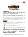
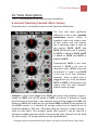
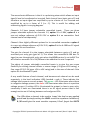
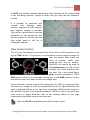
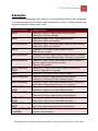
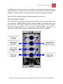
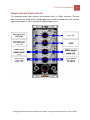
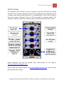
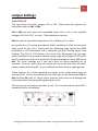
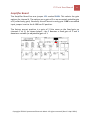
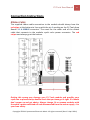
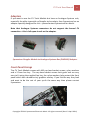
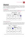
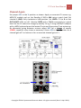
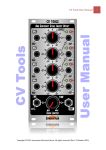
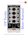
CV Tools User Manual
Copyright © 2011 Synovatron Electronic Music. All rights reserved. (Rev 1.2 April 2011)
1
CV Tools User Manual
2
Introduction
Thank you for purchasing the Synovatron CV Tools Module. This manual
explains what the CV Tools Module is and how it works.
The CV Tools Module is a 12HP (60mm) wide Eurorack analogue synthesizer
module and is compatible with the Doepfer™ A-100 modular synthesizer bus
standard.
The CV Tools Module is a versatile voltage processor intended for control
voltage manipulation such as adding, subtracting attenuating, amplifying and
offsetting. It can also be used with audio and gate signals to great effect.
Caution
Please ensure you use the CV Tools Module in accordance with these
instructions especially taking great care to connect the ribbon cable to the
module and the power bus correctly. Always double check!
Reversing or misconnecting the bus connector can result in
equipment damage and will invalidate the warranty.
Only fit and remove modules with the rack power off and
disconnected from the mains electricity supply for your own safety.
Refer to the connection section for ribbon cable connection instructions.
Synovatron Electronic Music cannot be held responsible for any damage or
harm caused through incorrect or unsafe use of this module. If in doubt, stop
and think. If you are still unsure of what to do then please contact
Synovatron for advice before proceeding.
Copyright © 2011 Synovatron Electronic Music. All rights reserved. (Rev 1.2 April 2011)
CV Tools User Manual
3
CV Tools Description
The CV Tools Module has two main sections as follows:-
4-channel Polarizing Cascade Mixer Section
Essentially this is a 4-channel mixer but with two main differences:
The first and most significant
difference is that it has a cascade
architecture which, unlike a
standard mixer that simply sums
all four inputs into one output,
has a summing stage at each of
the outputs OUT2, OUT3 and
OUT4 (denoted by the Σ symbol).
So OUT1 is added to OUT2, OUT2
is added to OUT3 and OUT3 is
added to OUT4.
Consequently OUT1 is just from
channel 1, OUT2 is the sum of
channels 1 and 2, OUT3 is the sum
of channels 1, 2 and 3, and OUT4
is the sum of all four channels.
However, when a patch lead is
plugged into any, or all, of outputs
OUT1 to OUT3 it disconnects that
output from the next channel’s
output summing stage.
Example: A patch lead plugged into OUT1 will ensure that whatever signal is
output on OUT1 will not be added to OUT2. So channel 1 becomes a single
gain/inversion channel and in this example, with nothing plugged into IN1, the
output on OUT1 will simply be the normalled VREF modified by the position of
the LEVEL control i.e. a variable DC voltage reference that could be set to
anywhere between -10V and +10V (depending on channel 1 jumper settings –
more on that later). This example shows that channel 1 can be used as a
reference voltage generator whilst the remaining three channels can be used
for other things – all the possibilities will be explained later.
Copyright © 2011 Synovatron Electronic Music. All rights reserved. (Rev 1.2 April 2011)
CV Tools User Manual
4
The second main difference is that it is a polarizing mixer which allows an input
signal’s level to be adjusted or inverted. Each channel has a basic gain of 2 and
therefore an input signal can amplified by up to a factor of 2 or inverted and
amplified by up to a factor of 2 (i.e. -2). This is useful for adding and
subtracting signals in varying degrees.
Channels 1-4 have jumper selectable normalled inputs. There are three
jumper selectable options for channels 1-3, option 1 is +5.00V, option 2 is a
user set voltage reference of 0.5V-2.5V or option 3 is no connection. Each
channel can be set separately.
Channel 4 has slightly different options for its normalled connection: option 1
is a user set voltage reference of 0.5V-2.5V, option 2 is the A-100 bus CV signal
or option 3 is no connection.
The gain for channel 4 is also jumper selectable between a gain of 2 and an
accurately set unity gain (gain of 1). This allows the normalled A-100 bus CV
signal to pass through with unity gain when the LEVEL control is set to 10. This
will allow an accurate CV of 1V/Octave to be added to the mix if required.
The object of jumper selectable normalled inputs is to give the user some
flexibility for setting channel offsets: a coarse range (+5V gives ±10V swing), a
fine range (0.5V-2.5V gives ±1V to ±5V swing) and in the case of channel 4 the
option for a calibrated CV path.
A very useful feature of each channel, and because each channel can be used
separately, is the level indication LEDS (marked – and +). These indicate the
voltage level present on each output. The green – LED illuminates when there
is a negative voltage present, the red + LED illuminates when there is a positive
voltage present. If neither LED is illuminated the output is close to zero volts,
conversely if both are illuminated there is an AC signal present that is fast
enough not to see it flashing between red and green LEDs.
The LEDs allow a channel to be used to ‘scope’ the level on any applied
patch lead by simply setting the LEVEL control to anywhere clockwise of
0 (10 would give the most sensitive response). Don’t forget that OUT2
Copyright © 2011 Synovatron Electronic Music. All rights reserved. (Rev 1.2 April 2011)
CV Tools User Manual
5
to OUT4 may include summed signals from other channels so put a patch lead
in the preceding channel’s output to make sure you only see one channel’s
activity.
It is possible to overdrive any
channel into clipping; either
positive, negative or both positive
and negative clipping is possible.
This can be a great way of creating
harmonics. In this image the sine
has been offset to clip the top and
then offset back to ±5V by a
subsequent channel.
Slew Limiter Section
This is a very low frequency low-pass filter where the cut-off frequency is set
by the TIME control. The purpose is to slow down control voltage changes so
that the output slews from one
level to another rather than
stepping from one to another.
Musically this would be used to
add portamento to a VCO control
voltage; one pitch blending into
the next. This is also called lag or
glide on other synthesizers. In the
MIN position there is no noticeable slewing but in the MAX position it takes
seconds to ramp up or down to the next voltage step.
As this function is mainly intended for slewing CVs for VCOs it is important that
this does not change the scale (or volts/octave) of the CV signal therefore the
input is buffered and has a very high input impedance (1MΩ) and the output is
also buffered to give a low output impedance (100Ω) in order to prevent any
scale errors or signal distortion due to the loading effects of the large
capacitance required to cause a slow slew rate.
Note that OUT4 is normalled to the Slew Limiter’s input.
Copyright © 2011 Synovatron Electronic Music. All rights reserved. (Rev 1.2 April 2011)
CV Tools User Manual
6
Examples
The 4-channel polarizing mixer section is very versatile and can be configured
in numerous ways just by patch lead connections. Here’s a table of what can
be done with just output patch leads.
Patched Outputs
OUT1
OUT2
OUT1 and OUT2
OUT3
OUT1 and OUT3
OUT2 and OUT3
OUT1, OUT2 and
OUT3
OUT4
OUT1 and OUT4
OUT2 and OUT4
OUT1, OUT2 and
OUT4
OUT3 and OUT4
OUT1, OUT3 and
OUT4
OUT2, OUT3 and
OUT4
OUT1, OUT2, OUT3
and OUT4
Configuration
Channel 1 forms a single-channel level control.
Channels 2 to 4 are unused.
Channels 1 and 2 form a two-channel mixer.
Channels 3 and 4 are unused.
Channels 1 and 2 form two single-channel level controls.
Channels 3 and 4 are unused.
Channels 1 to 3 form a three-channel mixer.
Channel 4 is unused.
Channel 1 forms a single-channel level control. Channels
2 and 3 form a two-channel mixer. Channel 4 is unused.
Channels 1 and 2 form a two-channel mixer. Channel 3
forms a single-channel level control.
Channel 4 is unused.
Channels 1, 2 and 3 form three single-channel level
controls. Channel 4 is unused.
Channels 1 to 4 form a four-channel mixer.
Channel 1 forms a single-channel level control.
Channels 2 to 4 form a three-channel mixer.
Channels 1 and 2 form a two-channel mixer. Channels 3
and 4 form a two-channel mixer. See example.
Channels 1 and 2 form two single-channel level controls.
Channels 3 and 4 form a two-channel mixer.
Channels 1 to 3 form a three-channel mixer.
Channel 4 forms a single-channel level control.
Channels 1 and 4 form two single-channel level controls.
Channels 2 and 3 form a two-channel mixer.
Channels 1 and 2 form a two-channel mixer. Channels 3
and 4 form two single-channel level controls.
Channels 1, 2, 3 and 4 form four single-channel level
controls. See example.
Copyright © 2011 Synovatron Electronic Music. All rights reserved. (Rev 1.2 April 2011)
CV Tools User Manual
7
In addition each level control or mixer channel can be used to either act upon a
signal applied via a patch lead to an input or can provide a variable DC offset
voltage if no patch lead is connected (refer to Input Board jumper settings)
Here are a few simple examples to demonstrate the principles:-
Two 2-channel mixers
This shows that by using two output patch leads that two 2-channel mixers can
be configured – OUT2 adds the offset applied to IN1 to the bipolar LFO signal
to give a 0 to +10V signal suitable for a clock or gate signal. A VCO’s square
wave and ramp waveforms are connected to IN3 and IN4 – the levels are
adjusted to effectively provide a ramp of twice the frequency at OUT4.
Copyright © 2011 Synovatron Electronic Music. All rights reserved. (Rev 1.2 April 2011)
CV Tools User Manual
8
Single channel level controls
This example uses each channel as separate level or offset controls. The top
two channels are used as DC voltage generators and the lower two are used as
signal attenuators – each channel is independent here.
.
Copyright © 2011 Synovatron Electronic Music. All rights reserved. (Rev 1.2 April 2011)
CV Tools User Manual
9
VCO CV mixer
This example uses channel 4 set to unity gain and the A-100 bus CV routed
through it (see jumper settings). Channel 3 is configured for a +5V VREF to give
a coarse tune control whilst channel 2 is configured for +0.5V VREF to give a
fine tune control. Channel 1 has an LFO connected to provide vibrato. The
output is routed via the Slew Limiter to give a portamento sound on the VCO.
Other examples will also be posted from time-to-time on the blog at
http://synovatron.blogspot.com
Please send any clever patches to [email protected] and they may
get featured on the blog.
Copyright © 2011 Synovatron Electronic Music. All rights reserved. (Rev 1.2 April 2011)
CV Tools User Manual
10
Jumper Settings
Input Board
The Input Board has four jumpers JP1 to JP4. These select the options for
normalled inputs to IN1 to IN4.
IN1 to IN3 can each have their normalled inputs set to +5V, a user settable
voltage of 0.5V to 2.5V* or none. *See adjustments section.
IN4 can have its normalled input set to +5V, A-100 bus CV or none.
As a guide the +5V setting provides an offset capability of ±10V (as channels
have a gain of ±2); this is mainly used for offsetting large signals like ADSR
envelopes or LFO waveforms and is especially good for forcing signals into
clipping. The 0.5V to 2.5V setting is for much finer adjustment e.g. you may
want a variable DC to provide an octave tuning range for a Doepfer A-110 VCO.
The CV position on channel 4 routes the CV signal available on the A-100 bus to
IN4. The ‘none’ settings are if you don’t want an offset capability on all
channels. To set to ‘none’ place the jumper on any one pin but leave the other
jumper socket disconnected – or you could just remove it but it might get lost.
These jumpers are a little awkward to change as the input board must be
removed first. Do this by undoing the five jack nuts on the front panel (IN1 to
IN4 and Slew IN) with an 11mm socket spanner; take care not to damage the
front panel when loosening and tightening the nuts.
The factory pre-set jumper positions are all +5V as shown below. Note JP5 is
hardwired and is not settable.
Copyright © 2011 Synovatron Electronic Music. All rights reserved. (Rev 1.2 April 2011)
CV Tools User Manual
11
Amplifier Board
The Amplifier Board has one jumper JP1 marked GAIN. This selects the gain
options for channel 4. The options are a gain of 2 or an accurately settable gain
of 1 (called unity gain). Generally this will be set to unity gain if IN4’s normalled
input jumper is set to the A-100 bus CV position.
The factory pre-set position is a gain of 2 (the same as the fixed gain on
channels 1 to 3). As shown below – the F denotes a fixed gain of 2 and V
denotes a variable (or adjustable) gain of 1.
Copyright © 2011 Synovatron Electronic Music. All rights reserved. (Rev 1.2 April 2011)
CV Tools User Manual
12
Connection Instructions
Ribbon Cable
The supplied ribbon cable connection to the module should always have the
red stripe at the bottom to line up with the pin 1 marking on the CV Tools Amp
Board’s J1 A-100BUS connector. The same for the other end of the ribbon
cable that connects to the modular synth racks power connector. The red
stripe must always go at the bottom.
Getting this wrong may damage your CV Tools module and possibly your
synth too so please always double check that you have got it right. If in doubt
don’t power up and get advice. Always change, fit or remove modules with
the synth’s power switched off and disconnected from the mains supply – for
your own safety.
Copyright © 2011 Synovatron Electronic Music. All rights reserved. (Rev 1.2 April 2011)
CV Tools User Manual
13
Adaptors
If you want to use the CV Tools Module but have an Analogue Systems rack,
especially the older type with no Doepfer style sockets, then Synovatron has an
adaptor specially designed for this – please contact Synovatron for details.
Note that Analogue Systems connectors do not support the bussed CV
connection – this is left open-circuit on the adaptor.
Synovatron Doepfer Module to Analogue Systems Bus (DM2ASB) Adaptor
Front Panel Fixings
The CV Tools Module comes with M3 cap head socket screws, nylon washers
and a 2.5mm hex key. The cap head socket screws look great and are very
easy to fit using the supplied hex key, the nylon washers help protect the front
panel which has a durable vinyl graphics overlay. If you like the way they look
and want to do the rest of your synth the same way then please contact
Synovatron.
Copyright © 2011 Synovatron Electronic Music. All rights reserved. (Rev 1.2 April 2011)
CV Tools User Manual
14
Adjustments
The voltage reference and gain adjustment pots are on the main amplifier
board. These adjustments should only be performed by a suitably qualified
person. The adjustments can be performed using a Digital Multi-Meter (DMM)
and small screwdriver or trim tool as follows:-
+5V reference
Disconnect the ribbon cable from J2. Measure the voltage on J2 pin 11 with
respect to 0V on J2 pin 5. Adjust RV6 for a DMM reading of 5.00V.
0.5V-2.5V reference
This is factory pre-set to 1.00V. This can be set as desired within the range 0.5V
to 2.5V. Measure the voltage on J2 pin 10 with respect to 0V on J2 pin 5.
Adjust RV8 for a DMM reading as required. Reconnect the ribbon cable to J2.
Copyright © 2011 Synovatron Electronic Music. All rights reserved. (Rev 1.2 April 2011)
CV Tools User Manual
15
Channel 4 gain
Set jumper JP1 to the V position as shown. Apply an accurate CV source e.g.
MIDI/CV module such as the Doepfer A-190 to IN4 using a patch lead. Set
channel 4 LEVEL fully clockwise to +10 position. Set LEVELs 1-3 to 0 so that
OUT1-OUT3 LEDs are off. Monitor OUT4 with a DMM connected via a patch
lead. Set the CV source to change by exactly 1V e.g. if using a MIDI/CV adaptor
with a MIDI keyboard press the lowest C note and then press C one octave up.
By alternately going between octaves adjust RV7 for a change of exactly
1.000V; repeat as many times as necessary. Return JP1 to the H position for a
channel gain of 2 or leave as is for an accurate channel gain of 1.
Copyright © 2011 Synovatron Electronic Music. All rights reserved. (Rev 1.2 April 2011)
CV Tools User Manual
16
CV Tools Specification
4-channel Polarizing Cascade Mixer
Channel 1
Input: 3.5mm jack IN1
Input impedance: 100kΩ (±1%)
Normalled input: VREF - jumper selectable to +5V, 0.5V-2.5V or none
Bandwidth: DC-15kHz (-3db)
Gain: LEVEL control variable 0 to ±2 (±3%)
Output: 3.5mm jack OUT1 - Normalled to Channel 2 output mixer
Output impedance: 1kΩ (±1%)
Output indication: ±LEDs
Channel 2
Input: 3.5mm jack IN2
Input impedance: 100kΩ (±1%)
Normalled input: VREF - jumper selectable to +5V, 0.5V-2.5V or none
Bandwidth: DC-15kHz (-3db)
Gain: LEVEL control variable 0 to ±2 (±3%)
Output: 3.5mm jack OUT2 - Normalled to Channel 3 output mixer
Output impedance: 1kΩ (±1%)
Output indication: ±LEDs
Channel 3
Input: 3.5mm jack IN3
Input impedance: 100kΩ (±1%)
Normalled input: VREF - jumper selectable to +5V, 0.5V-2.5V or none
Bandwidth: DC-15kHz (-3db)
Gain: LEVEL control variable 0 to ±2 (±3%)
Output: 3.5mm jack OUT3 - Normalled to Channel 4 output mixer
Output impedance: 1kΩ (±1%)
Output indication: ±LEDs
Copyright © 2011 Synovatron Electronic Music. All rights reserved. (Rev 1.2 April 2011)
CV Tools User Manual
17
Channel 4
Input: 3.5mm jack IN4
Input impedance: 100kΩ (±1%)
Normalled input: VREF - jumper selectable to +5V, A-100 Bus CV or none
Bandwidth: DC-15kHz (-3db)
Gain: LEVEL control variable 0 to ±2 (±3%) or 1 (set by RV7) with LEVEL control
fully clockwise - jumper selectable
Output: 3.5mm jack OUT4 and Slew Limiter input
Output impedance: 1kΩ (±1%)
Output indication: ±LEDs
Slew Limiter
Input: 3.5mm jack IN
Input impedance: 1MΩ (±1%)
Normalled input: Channel 4 output OUT4
Slew range: 0.5ms-1000ms
Gain: 1
Output: 3.5mm jack OUT
Output impedance: 100Ω (±1%)
General
Dimensions
3U x 12HP (128.5mm x 60.6mm)
Power consumption
+12V @ 20mA max, -12V @ 20mA max, +5V is not used
Reference voltage (VREF)
Jumper selectable at each mixer input. Channels 1-3: 5.00V (set by RV6), 0.5V2.5V (set by RV8), Channel 4: 5.00V (set by RV6), CV from A-100 bus
A-100 Bus utilisation
±12V, 0V, CV used; +5V and Gate are not used
Contents
CV Tools Module, 200mm 16-way ribbon cable, 4 sets of M3 cap head socket
screws, nylon washers and a 2.5mm hex key
Copyright © 2011 Synovatron Electronic Music. All rights reserved. (Rev 1.2 April 2011)
CV Tools User Manual
18
Environmental
All components used on the CV Tools Module are RoHS compliant. To comply
with the WEEE Directive please do not discard into landfill – please recycle all
Waste Electrical and Electronic Equipment responsibly – please contact
Synovatron to return the CV Tools module for disposal if required.
Warranty
The CV Tools Module is guaranteed against defective parts and workmanship
for 12 months from date of purchase. Note that any physical or electrical
damage due to misuse or incorrect connection invalidates the warranty. A low
cost repair service will be available for any repairs outside of warranty
conditions.
Quality
The CV Tools Module is a high quality professional audio device that was
lovingly and carefully designed, built, tested in the United Kingdom by
Synovatron Electronic Music. Please be assured of my commitment to
providing good reliable and usable equipment! Any suggestions for
improvements will be gratefully received.
Thank you and happy music making.
Tony.
Contact details
Tony Steventon
Synovatron Electronic Music
104 Twyford Avenue
Portsmouth
PO2 8DJ
UK
M: +44 (0) 7889 053435
T: +44 (0) 2392 669339
E: [email protected]
W: http://synovatron.blogspot.com
Copyright © 2011 Synovatron Electronic Music. All rights reserved. (Rev 1.2 April 2011)