1
Z 5169
Quality for the world
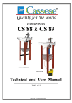
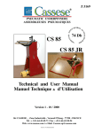
CS 85
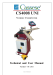
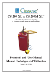
PNEUMATIC FRAME ASSEMBLING MACHINE
Technical and User Manual
09 / 2011
Cassese / Communication
Fig N°1
BP
Po
Pr
BP
E
P2
B2
H
P1
B
Fig N°3
AS
B1
St
CS 85
PNEUMATIC FRAME
ASSEMBLING MACHINE
Ta
ANGLE ADJUSTMENT
SCREW
LIMIT STOP
1st BACKFENCE
2nd BACKFENCE
ROTATING BASE
CABINET
90° JOINING ANGLE
ASSEMBLY
WIRE FOR WEDGE
PUSHING SPRING
WEDGE DISTRIBUTOR
LEVER FOR
STAPLING POSITION
(inside of frame)
LEVER FOR
STAPLING POSITION
(outside of frame)
LEVER FOR ONLY
ONE OR INTERMEDIATE
POSITIONS
FOOT PEDAL
TOP PRESSER
BRACKET
TOP PRESSER
BASE CABINET
LOCKERS
EXTENSION TABLE
FRONT
Ta
Fig N°2
F
F
St
St
P
St
P
WORK POSITION REFERENCE
1
AS
B
B1
B2
BP
E
F
H
P1
P2
P3
P
Po
Pr
St
Ta
CS 85 - USER’S TECHNICAL MANUAL
CONTENTS
Page
2
INTRODUCTION
ACCESSORIES SUPPLIED WITH THE MACHINE
TECHNICAL SPECIFICATIONS
OPTIONS
GUARANTEE
3
PUTTING INTO OPERATION
ADJUSTMENTS
SELECTION OF STAPLING POSITIONS
SETTING AND STORING THE STAPLING POSITIONS
SELECTION OF TOP PRESSER
ADJUSTMENT OF THE ASSEMBLY ANGLE
4
4-5
6
7
USE
MEANS OF ASSEMBLY
LOADING THE WEDGE CARTRIDGE ON MACHINE
8
JOINING THE FRAME
MAINTENANCE
LUBRICATION
CLEARING A WEDGE STUCK IN THE WEDGE DISTRIBUTOR
IN CASE OF HAMMER & WEDGE JAMMING
CS 85 09 / 2011
9
9
10
INTRODUCTION
You have just bought a CS 85 frame joining machine, so we congratulate on your sensible choice and thank
you for your trust in Cassese products. The CS 85 benefit from the experience of the joining machines that
brought Cassese a certain reputation. It makes it possible to join wooden mouldings of all profiles ( patent n°
7522814). The CS 85 is designed to allow the operator to move all around the machine.The joining operation is
carried out by using metal wedges especially designed to perform a tight join. These wedges come in throw-away
plastic cartridges, without glue, individually lubricated and rust- protected for the toughest challenges.
IMPORTANT: You should not use other wedge cartridges than those manufactured by Cassese and
marketed by official Cassese distributors (registered mark CS). BEWARE OF COPIES.
ACCESSORIES SUPPLIED WITH THE MACHINE
1 support for triangle top presser with 1 black rubber triangle (for hardwoods) + 1 white
triangle (softwoods) / 1 spare hammer (wedge driver blade) / 4 Allen keys for hexagonal
nuts (2.5-3-4-5 mm)/1 wedge pusher tool /1 quick release female connection /
1 extension table
TECHNICAL SPECIFICATIONS OF CS 85
Minimum moulding width : 3mm (1/8”) Minimum moulding height : 7 mm (¼”)
Furthest stapling position from back of moulding (at 45°) : 74 mm (3”) / Wedge sizes in
cartridges of 275 pieces : 3, 5, 7, 10, 12 and 15 mm.Two wedge types : for soft and for
hardwoods / Energy needed : compressed air 6-7 bars ( +/- 100 p.s.i. ) /
Machine gross weight : 40 kg (85 lbs)
Dimensions : CS 85 : 507mm(20”)x 507mm (20”)(w/out ext. table)x1100 mm high (44”)
Cassese Item #
Z 4511
Z 4512
OPTIONAL ACCESSORIES AVAILABLE
Description
120° Joining angle assembly (for 6-sided frames)
135° Joining angle assembly (for 8-sided frames)
Other top pressers :
Cassese Item #
Description
Z 4556
White Triangle with support
Z 887
Black Triangle with support
Z 4558
Short orange rubber with support
Z 4559
Short green rubber with support
Z 4560
Long orange rubber with support
Z 4561
Long green rubber with support
Z 1800
Long orange rubber w/out support
Z 1804
Long green rubber w/out support
Z 1783
Short orange rubber w/out support
Z 1791
Short green rubber w/out support
For use on
Soft wood
Hardwoods
Softwoods
Hardwoods
Softwoods
Hardwoods
Softwoods
Hardwoods
Softwoods
Hardwoods
Maxi moulding height
48 mm
(2 ”)
48 mm
(2 ”)
48 mm
(2”)
48 mm
(2 ”)
33 mm (1 1/4”)
33 mm (1 1/4”)
63 mm (2 1/2”)
63 mm (2 1/2”)
78 mm (3 1/8”)
78 mm (3 1/8”)
GUARANTEE
One year guarantee for parts and labour against manufacturing defects. Wear parts and
those damaged as a result of non appliance with the instructions of the present manual are
excluded from the guarantee.
2
PUTTING INTO OPERATION
1 ) UNPACKING & REASSEMBLY
P
BF
B
BP
Po
Ta
fig.A
Fig B
Fig C
- Keep the package of the machine so, that the arrows drawn on the outside stand up, (see Fig A)
- Open the parcel. Remove machine’s table Ta and the foam protection (see Fig. B).
- (See Fig C) Pressing down the crossing wood piece B, loosen and remove one of the two feet of
the machine that are holding the wood piece B in place. The wood piece B is pushed up by the
machine’s top presser; therefore remove it slowly until the machine’s top presser is completely
free. Fix the removed foot back on machine.
- Remove the pedal P and the accessory box now. (See detail of content page 5)
- Remove the turning upper cabinet BP and the bottom cabinet BF. (Fig.C)
- The bottom cabinet BF is upside down; put it right on its feet.The nut of the foot you removed
is in the necessary box.
- Place the upper cabinet BP on the bottom cabinet BF.
CLOSING CLIPS - Inside of the upper cabinet there is a white
Fig D
air tube rolled up. UnrollCP
it and cross its free
end through the bottom cabinet.
- Close the locking clips ( figD ) to fix the
upper & bottom cabinets.
M
AX
AX
S1
S2
OPENING CLIPS
Connecting
the air pedal
Fig E
Table screws
Fix the table extension with the four
screws ( fig E ).Adjust the level of the machine
to the floor with its 4 adjustable feet.
Push the end of
white tube
coming out of
machine here in
Quick release
male connection
(connect air supply here )
3
ADJUSTMENTS
SELECTION OF STAPLING POSITIONS
The CS 85 is designed to join mouldings in one or two places (positions) without limitation of the
number of wedges stacked in any of those places. The selection depends on the width and thickness
of the moulding to join.
2 mm MINIMUM (Approx.1/8’’)
2 mm MINIMUM (Approx.1/8’’)
As a general rule a MINIMUM 2 mm clearance (less than 1/8”) above the wedges shall
be respected.
Same sized wedges can be stacked in order to avoid to have to change the cartridge size
when joining frames with different thickness.
AS A GENERAL RULE, THE JOINING MUST BE CARRIED OUT AS
CLOSE TO THE THICKEST MOULDING PART(S) AS POSSIBLE .
SETTING AND STORING THE STAPLING POSITIONS
Unlock the stapling position lock handles P1, P2 and P3.
90° JOINING
ANGLE ASSEMBLY
P3
B1
B
P1
4
P2
Standing in the work position used as reference for explanations (behind the machine; see
Fig 2, page 1), with your left hand, put the first moulding chop in front of the left (1st)
backfence B1 and bring the chop in contact
P2
with the right (2nd) backfence B2.
For the stapling position close
to the outside of the frame :
B
Move forward the 90° joining angle assembly
E until the place where you want to insert the
wedge(s) has been reached by the WEDGE
EXIT (see picture). Then bring the lever P2
against the limit stop B and tighten it.
B1
E
WEDGE
EXIT
B2
FRONT OF MACHINE
For the stapling position close to the inside
of the frame :
Move the 90° joining angle backwards, until
you have reached the furthest
position to the inside of the frame where you
want to insert wedge(s).
Then bring the lever P1 against the limit stop
B and tighten the lever.
P1
E
Now the two positions of joining are set and
the machine’s 90° angle can move only
within the limits of these two positions.
In case you would like to insert wedges in between these two positions, or if you are
working with a very small moulding and would like to insert wedges only in one place, you
can use the lever P3 located on the limit stop B.
This intermediate lever P3 also enables you to stack wedges (on top of each other in the
same position) without risk of missing the stacking operation (not pushing the first wedge
deeper inside).
WEDGE
EXIT
P3
B
E
5
SELECTION OF TOP PRESSER
1
2
3
4
This new version top presser comes now with your
CS 85 as a standard feature. Its height can be
adjusted with the pin so that the machine can work
up to 78 mm (3"1/8) tall mouldings. Pay attention to
keep always maximum 30mm (1"1/4) distance
between the top presser and the mouldings and to
keep the rubber triangle parallel to the 90° angle
assembly (backfences)
G
The moulding height capacity of the new
triangle top presser support for its 4 positions
:
1) 37 mm (1"1/2)
2) 53 mm (2"1/8)
3) 68 mm (2"3/4)
4)78 mm (3"1/8)
BLACK TRIANGLE PRESSER
WHITE TRIANGLE PRESSER
GREEN RUBBER
ORANGE RUBBER
HARD WOOD
SOFT WOOD
HARD WOOD
SOFT WOOD
30 et 45 mm
30 et 45 mm
OPTIONAL ACCESSORY (Cassese item # Z.6233)
A similar adjustable support for the round rubber top pressers is no
w available with 3 positions for its height.As the round rubbers are
available in two lengths (30mm & 45mm) and in two hardness
finishes (orange for softwoods & green for very hardwoods), the
maximum height of moulding that this optional round rubber support
can work in its three positions are :
Position hole # With short round rubber With long round rubber
1
2
3
37 mm
53 mm
68 mm
22 mm
37 mm
53 mm
6
Z6625
ADJUSTMENT OF THE ASSEMBLY ANGLE
If several cutting machines are being used in your production or if you receive your mouldings already cut by your suppliers (chop service), the angles of the mouldings will be slightly
different from one cutting machine to the other. The joining angle of your CS 85 can be
adapted to find precisely the cutting angle of your cutting machine.
If the corner is open towards outside, unscrew (turn anti-clockwise) the angle adjustment
screw AS (see Fig 1 page 1) a little to correct the fault and check again.
Outside
Inside
If you get this result, check your cutting angle, which is wrong
in this case because it is less than 45°.
Carry out the adjustment of the angle of your cutting
machine.
IT IS IMPOSSIBLE TO MAKE A RECTANGLE
FRAME WITH ANGLES SMALLER THAN 90°.
If the corner is open towards inside, screw in (turn clock-wise) the angle adjustment screw
AS (Fig 1 page 1) to correct the fault.
7
USE
MEANS OF ASSEMBLY
The joining is performed by using metal wedges, a Cassese invention, designed to ensure very tight corners. Six sizes are available :
3, 5, 7, 10, 12 and 15 mm . They come in throw-away cartridges
that are colour-coded per size for easy identification. Cartridge
wedges exist in two versions : NORMAL for soft and normal
timbers and HW for very hard timbers. These hardwood wedges
are to be used only on hardwoods. Your CS 85 machine is designed to
use all sizes of Cassese cartridges without having to change any parts
on the machine or to adjust anything.
For the long term performance and reliability of your CS 85, only use
genuine CASSESE cartridge wedges. Beware of counterfeit products.
LOADING AND CHANGING THE WEDGE CARTRIDGE ON MACHINE
Pull the wire with ball of the wedge pusher spring F (fig.2, p1) fully out.
If there is a cartridge on machine, holding the wire pulled out, remove it by simply sliding out
and lifting the cartridge.
Holding the wire pulled out, put a new cartridge on machine and pay attention that it is fully
inserted in the wedge distributor’s window.
Release gently the wire with ball of the wedge pusher spring F.
JOINING THE FRAME
After selecting and setting the stapling positions (page 4 & 5), adjusting the assembly angle
(page 6), checking the distance between the top presser and the moulding (page 6) and loading
the best suited type (normal or hardwood) and size of wedges (page 7),
1- Put the first (left-hand) moulding in front of the fence B1 and push it so that its mitre end
reaches the other fence B2.
2- Holding it so, put the second moulding chop against fence B2 and slide it until it reaches the
first moulding.
3- Holding the mouldings in place against each other, hold the backfences B1 & B2 with your
thumbs and make the angle assembly slide backwards until the lever P1 reaches the limit stop B.
You can eventually tighten the intermediate lever P3 to be sure that the position remains fixed.
4- Still holding the mouldings well profiled against each other, press the pedal P (Fig 2, p.1).
Release the pedal after one to two seconds; one wedge must have been fully inserted.
If you intend to stack a second (or third) wedge in the same position, just push the pedal again . In
this case using (tightening) the lever P3 will enable you to stack them more easily.
5- If there is a second stapling position chosen (with lever P2), just repeat the same operation by
pushing forward the mouldings and the angle assembly of the machine until P2 reaches the limit
stop B. And repeat step 4 above.
8
MAINTENANCE
1) LUBRICATION
Periodically, remove the wedge distributor (Fig 1, block H) and clean it (by air gun) without dismounting it.
It is recommended to lubricate the hammer (driver blade) periodically. To do so, remove the wedge
distributor (blockH) and put a small quantity of grease in the bottom hole of the wedge distributor.
The hammer will be lubricated every time it crosses the wedge distributor.
2) CLEARING OF A WEDGE STUCK IN THE WEDGE DISTRIBUTOR
If you push the pedal half way or release too quickly, a wedge may be half engaged in the wedge
distributor.
- In this case, close the air valve.
- Try to remove the cartridge that is in position. If it resists, use the wedge removal tool to push
down the wedge back in the cartridge.
- Pay attention not to make penetrate the tool more than 6mm (¼”) into the wedge distributor.
It is important not to leave a wedge half engaged in the wedge distributor, as it may cause the
insertion of two wedges when you join the next corner or may cause the jamming of the
hammer (the driver blade) in the wedge distributor.
- In case of the hammer (driver blade) jamming with a wedge in the wedge distributor, see the following section (3).
WEDGE REMOVING TOOL
6mm MAXIMUM ( 1/4’’ )
WEDGE DISTRIBUTOR
( BLOCK H )
WEDGE EXIT
9
MAINTENANCE
3 ) IN CASE OF HAMMER AND WEDGE JAMMING
AFTER A HAMMER JAMMING INCIDENT, ALWAYS REPLACE
THE HAMMER WITH A BRAND NEW ONE.
GF1
A
D
GF2
F
E
WEDGE
DISTRIBUTOR
(BLOCK H)
B
LOCKING SCREW
C
SCREW
POSITIONS
BLOCK H
- Remove the cartridge that is on machine, and the top presser.
- Using the 3mm Allen key, loosen the locking screw of the wedge distributor Block H.
- Then lift the top presser’s bracket arm by hand. The wedge distributor will come out of its
housing.
- Remove it from the machine.
- The old hammer (wedge driver blade) is stuck in the wedge distributor : first try to remove it
with a pair of pliers. If not possible, unscrew the two central screws (GF1, GF2) that hold the
fixed (square) guide of Block H in place. Use for this the smaller (2.5mm) Allen key supplied
with the machine. Remove the fixed guide completely to free the old hammer. If still not possible
to get rid of the old hammer, remove the four screws (A, B, C, D) and open the block H. (Two
factory set locator pins E & F allow the plates to be re-positioned precisely again.)
- Remove the old hammer. Assemble the Block H back again.
Putting a new hammer (driver blade) :
- Put a drop of grease in the bottom hole of the wedge distributor (block H).
- Insert a new hammer into block H from the top with the hole of the hammer downwards.
- Re-position the wedge distributor in its housing on the machine with the window towards the
cartridge.
- If the upper end of the hammer stays out of the block H, push it fully in with a piece of wood or
moulding.
While keeping the moulding in place (on block H) and pressing on it, pull up the top presser’s
bracket arm Po (Fig1 p1) with a quick movement.
The new hammer must have taken its position in the mechanism automatically.
- Check with your finger that the block H does not stay out of the machine (higher than the work
level) and tighten the locking screw of block H. No need to tighten too much.
- The machine is ready to work again.
If you have any difficulty to remove the block H from the machine,
push down with your hands the top presser’s bracket arm.
This should free the block H that is stuck with the hammer.
For any other problem, don’t hesitate to contact your regular source of Cassese products.
10