1
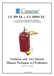
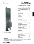
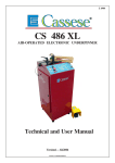
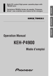
Z 5169
DE BRUIT
-E
AU
L
E
74 Db
EL DEL
NIV
R
DO
UI
NO
IS
CS 85
VEL - NIV
LE
E
PNEUMATIC UNDERPINNERS
ASSEMBLEUSES PNEUMATIQUES
CS 85 JR
Technical and User Manual
Manuel Technique & d’Utilisation
Version 1 - 10 / 2000
Sté CASSESE , Zone Industrielle - Verneuil l’Etang - 77390 - FRANCE
Tel : + 33.1.64-42-49-71 / Fax : +33.1.64-42-58-94
Web: www.cassese.com / e-Mail: [email protected]
Cassese / Communication
$
! "
'& (
+
%&
$
- $
;
,
.
0 12
%67 8
,
&
;
0
6
-
-
""
)
$
3$
96
&
2
2
& &
"
+
1
$<-5
$
3 3 <
"
&
=
"& "
"& "
C
$
+&
+&
0
C
C
2
& 2
& "
#
!
" '&
"/
-;$
+
"
#
-
;
--;
- $
;
$
;
-
"
"& "
3
&
0 68? .<
&"
"& "
+ " 15
%
+ "
,# / "
&
96
8
$<-5
<
1
=
,
5
? "2
$
& 4 2
"& #!"
B6 &
:)
+ ""
!
& 4
& 4
& 4
& 4
"& #!"
"
&
#
B6 &
&&
>
,
C
"
%67
/ " #
& 4 12
5$
&&
&
&
&
& #!" &
/" &
& 4 2
? "2.
3$ 3 <
3
3
3
"
-
>
&
0
2
0
2
0
2
0
2
.& "
"&
&"
+ "
,
:)
#
* &
#
5
"
" &
@ 3 A
<
A
5
2
2
2
2
5$
5
5
5
"
@ 3
A
&"
" &
&
5
&@
&
# & &
&"
&
15
"
+ * " #
,!&
&
D
<
A
$
$
$
$
+ "
/
.& "
%
!
+ "
0
,1
& 2
& 2
&
&
$
$
;;;
&
+
/ "& E
"
6 #!"
"
) /"
"
"
& 4 ,1 5
? "2
? "2
4@ 3 A
? "2
$
? "2
$
! & 4 "!
4@ 3 A
? "
4" !
"
4@ 3 A
F ! &
E
3
5 $
5
5$
+ ""
5
+ *"
&
& "&
3
2
$
2
$
&(" "
;
;
$
&
? "
" &/
!
&
&
&
6
;
$
&
- ;
-$
--;
;
$$
;
$
$
$
;
-;
$
$
---$
%
%
%
+ "
,& #
+
!
0
2
0
2
0
2
0
2
E
2
+ "
&# &
!
,# ! 5
"& +
+ "
,
&
+ " &
&"
0
"
+ "
, 1
0 12
0 12
"
&
&
"
3
5 $
5$
5$
3
&
33
3
3
3 $
3$
&"
&"
& 4 2
& 4 2
& 4 2
& 4 2
& 4 2
+ ""
5
2
&
& 5!
"
"# ! 5 #
#
"
& /
&
&&
"
5
)#
/
&
1
3
3$
&"
&"
&
&" "& #
#& / # H %
1 @ $<
& & # #
"
H
,
$
;
"E
C #& / #
&
#
55
5
5
5 $
&"
2 5 #
5
"
&"
G "
"
#
&
+
,
5
"
2
&
"
& 4
+ ""
"
,
" &1
1
& 4 12
5
& 4 12
5$
F #
! &
2
&
&" H
! &
4 #
! & & #
,& #
&" H & 4
F #
"& " & 4 "!
& #
4& H
F #
&"
"
"
Fig N°1
BP
Po
E
BP
B2
Pr
P3
H
B1
P1
P2
B
Fig N°3
F
AS
St
CS 85
PNEUMATIC FRAME
ASSEMBLING MACHINE
ANGLE ADJUSTMENT
SCREW
LIMIT STOP
1st BACKFENCE
2nd BACKFENCE
ROTATING BASE
CABINET
90° JOINING ANGLE
ASSEMBLY
WIRE FOR WEDGE
PUSHING SPRING
WEDGE DISTRIBUTOR
LEVER FOR
STAPLING POSITION
(inside of frame)
LEVER FOR
STAPLING POSITION
(outside of frame)
LEVER FOR ONLY
ONE OR INTERMEDIATE
POSITIONS
FOOT PEDAL
TOP PRESSER
BRACKET
TOP PRESSER
BASE CABINET
LOCKERS
EXTENSION TABLE
FRONT
Ta
Ta
F
St
F
St
P
St
P
Fig N°2
WORK POSITION REFERENCE
1
AS
B
B1
B2
BP
E
F
H
P1
P2
P3
P
Po
Pr
St
Ta
CS 85 - USER’S TECHNICAL MANUAL
CONTENTS
Page
2
INTRODUCTION
ACCESSORIES SUPPLIED WITH THE MACHINE
TECHNICAL SPECIFICATIONS
OPTIONS
GUARANTEE
PUTTING INTO OPERATION
REASSEMBLY & PUTTING INTO OPERATION
3 (cs85)
3A (cs85Jr)
ADJUSTMENTS
4
4-5
6
6
SELECTION OF STAPLING POSITIONS
SETTING AND STORING THE STAPLING POSITIONS
SELECTION OF TOP PRESSER
ADJUSTMENT OF THE ASSEMBLY ANGLE
USE
7
MEANS OF ASSEMBLY
LOADING THE WEDGE CARTRIDGE ON MACHINE
JOINING THE FRAME
MAINTENANCE
LUBRICATION
CLEARING A WEDGE STUCK IN THE WEDGE DISTRIBUTOR
IN CASE OF HAMMER & WEDGE JAMMING
CS 85 & CS 85Jr
10 / 2000
8
8
9
INTRODUCTION
You have just bought a CS 85 OR CS85Jr frame joining machine, so we congratulate on your sensible choice
and thank you for your trust in Cassese products. The CS 85 benefits from the experience of the joining machines that brought Cassese a certain reputation. It makes it possible to join wooden mouldings of all profiles
( patent n° 7522814). The CS 85 is designed to allow the operator to move all around the machine.The joining
operation is carried out by using metal wedges especially designed to perform a tight join. These wedges come
in throw-away plastic cartridges, without glue, individually lubricated and rust- protected for the toughest
challenges.
IMPORTANT: You should not use other wedge cartridges than those manufactured by Cassese and
marketed by official Cassese distributors (registered mark CS). BEWARE OF COPIES.
ACCESSORIES SUPPLIED WITH THE MACHINE
1 support for triangle top presser with 1 black rubber triangle (for hardwoods) + 1 white
triangle (softwoods) / 1 spare hammer (wedge driver blade) / 4 Allen keys for hexagonal
nuts (2.5-3-4-5 mm)/1 wedge pusher tool /1 quick release female connection /CS85:1 extension table - CS85Jr: 2 attachment arms + 4 screws / 1 insert with support (fixed on machine).
TECHNICAL SPECIFICATIONS OF CS 85 & CS 85 Jr
Minimum moulding width : 3mm (1/8”) Minimum moulding height : 7 mm (¼”)
Furthest stapling position from back of moulding (at 45°) : 74 mm (3”) / Wedge sizes in
cartridges of 275 pieces : 5, 7, 10, 12 and 15 mm.Two wedge types : for soft and for
hardwoods / Energy needed : compressed air 6-7 bars ( +/- 100 p.s.i. ) /
Machine gross weight :CS 85 = 40 kg (85 lbs) / CS 85Jr = 20 kg ( 42.5 lbs)
Dimensions : CS 85 : 507mm(20”)x 507mm (20”)(w/out ext. table)x1100 mm high (44”)
CS 85Jr : 300mm (12 ” ) x 490 mm (191/2 ”) x 535 mm high (211/2 ”)
Cassese Item #
Z 4511
Z 4512
OPTIONAL ACCESSORIES AVAILABLE
Description
120° Joining angle assembly (for 6-sided frames)
135° Joining angle assembly (for 8-sided frames)
Other top pressers :
Cassese Item #
Description
Z 4556
White Triangle with support
Z 887
Black Triangle with support
Z 4558
Short orange rubber with support
Z 4559
Short green rubber with support
Z 4560
Long orange rubber with support
Z 4561
Long green rubber with support
Z 1800
Long orange rubber w/out support
Z 1804
Long green rubber w/out support
Z 1783
Short orange rubber w/out support
Z 1791
Short green rubber w/out support
For use on
Soft wood
Hardwoods
Softwoods
Hardwoods
Softwoods
Hardwoods
Softwoods
Hardwoods
Softwoods
Hardwoods
Maxi moulding height
48 mm
(2 ”)
48 mm
(2 ”)
48 mm
(2”)
48 mm
(2 ”)
33 mm (1 1/4”)
33 mm (1 1/4”)
63 mm (2 1/2”)
63 mm (2 1/2”)
78 mm (3 1/8”)
78 mm (3 1/8”)
GUARANTEE
One year guarantee for parts and labour against manufacturing defects. Wear parts and
those damaged as a result of non appliance with the instructions of the present manual are
excluded from the guarantee.
2
INTRODUCTION
Vous venez d’acquérir une CS 85. Nous vous félicitons pour votre bon choix et vous remercions pour
votre confiance. La CS 85 bénéficie de l’expérience des assembleuses qui ont fait la notoriété de Cassese.
La CS 85 permet l’assemblage des moulures en bois de tous profils (Brevet n’ 7522814) ,et est conçue
pour permettre à l’opérateur de se déplacer tout autour de la machine. L’assemblage est réalisé par des
agrafes métalliques spécialement étudiées pour un serrage parfait.
IMPORTANT : Ne pas utiliser d’autres chargeurs que les chargeurs Cassese (Marque déposée CS)
ACCESSOIRES FOURNIS AVEC LA MACHINE
- 1 support triangle avec :
- 1 triangle élastomère Noir (bois durs),
- 1 triangle élastomère Blanc (bois tendres) .
( Hauteur maxi de la moulure : 35 mm)
- 1 marteau de rechange / 4 clés hexagonales ( 2.5 - 3 - 4 - 5 mm ) / l outil de remise en place
d’agrafes dans le chargeur / CS85: 1 table de travail - CS85Jr : 2 bras d’appui de table +4 vis CHC
5x20 + 1 entretoise d’appui avec support ( monté sur la machine)/ 1 raccord rapide
SPECIFICATIONS
- Largeur minimum de la moulure : 3 mm . Hauteur minimum de la moulure : 7 mm .
- Distance maximum du point d’agrafage jusqu’au dos de la moulure (coupe à 45°) : 74 mm.
- Taille des agrafes en conditionnement de 275 : 5, 7, 10, 12 et 15 mm .
- Deux types d’agrafes : bois tendres, bois durs .
- Alimentation : Air comprimé - 3 litres par cycle à 6bars.
- Poids de la machine : CS 85 = environ 40 kgs . CS 85Jr = 20 Kgs.
- Encombrement :
CS 85 : 507 mm x L 507 mm x H 1100 mm (sans table de travail)
CS 85Jr : 300 mm x L 490 mm x H 535 mm.
OPTIONS DISPONIBLES A LA VENTE
Z 4556
Z 887
Z 4558
Z 4559
Z 4560
Z 4561
Z 1791
Z 1783
Z 1804
Z 1800
Z5099
Z5098
Z 4511
Z4512
Hauteur Maxi
de la moulure
Sous-Ensemble Support triangle blanc
48 mm
Sous-Ensemble Support triangle noir
48 mm
Sous-Ensemble Support élastomère orange (long: 30 mm)
48 mm
Sous-Ensemble Support élastomère vert (Iong: 30 mm )
48 mm
Sous-Ensemble Support élastomère orange (Iong: 45 mm)
33 mm
Sous-Ensemble Support élastomère vert (Iong: 45 mm )
33 mm
Elastomère vert (Iong: 30 mm) (Monté sans support)
78 mm
Elastomère orange (long: 30 mm) (monté sans support)
78 mm
Elastomère vert
(long: 45 mm) (Monté sans support)
63 mm
Elastomère orange (Iong: 45 mm) (monté sans support)
63 mm
Sous-Ensemble Support triangle rallongé blanc
18 mm
Sous-Ensemble Support triangle rallongé noir
18 mm
Sous-Ensemble Equerre coulissante 120°
Sous-Ensemble Equerre coulissante 135°
GARANTIE
La CS 85 est garantie l an, pièces et main d’oeuvre contre tous vices de fabrication. Les
pièces d’usure et celles endommagées par une utilisation non conforme aux dispositions
de la présente notice sont exclues de cette garantie.
2
PUTTING INTO OPERATION
1 ) UNPACKING & REASSEMBLY
P
BF
B
Ta
BP
Po
fig.A
Fig C
Fig B
- Keep the package of the machine so, that the arrows drawn on the outside stand up, (see Fig A)
- Open the parcel. Remove machine’s table Ta and the foam protection (see Fig. B).
- (See Fig C) Pressing down the crossing wood piece B, loosen and remove one of the two feet of
the machine that are holding the wood piece B in place. The wood piece B is pushed up by the
machine’s top presser; therefore remove it slowly until the machine’s top presser is completely
free. Fix the removed foot back on machine.
- Remove the pedal P and the accessory box now. (See detail of content page 5)
- Remove the turning upper cabinet BP and the bottom cabinet BF. (Fig.C)
- The bottom cabinet BF is upside down; put it right on its feet.The nut of the foot you removed
is in the necessary box.
- Place the upper cabinet BP on the bottom cabinet BF.
CLOSING CLIPS - Inside of the upper cabinet there is a white
Fig D
air tube rolled up. UnrollCP
it and cross its free
end through the bottom cabinet.
- Close the locking clips ( figD ) to fix the
upper & bottom cabinets.
M
AX
AX
S1
S2
EA
OPENING CLIPS
Connecting
the air pedal
Fig E
Table screws
Quick release
male connection
(connect air supply here )
Fix the table extension with the four
screws ( fig E ).Adjust the level of the machine
to the floor with its 4 adjustable feet.
Push the end of white tube
coming out of machine here in.
3
REASSEMBLY & PUTTING INTO OPERATION the CS 85 Jr
Fix the 2 attachment arms of the machine to the body of the CS 85 Jr with the screws
V1, V2, V3 and V4 ; the allen wrench (#5) needed is supplied with the machine. See Fig.1.
Hang your machine CS 85 Jr to any table with a minimum thickness of 30mm (1”1/4).
Fig 1
Fig 2
V2
V1
V4
V3
VT1
INSERT
STOP
SCREW
LOCKING
NUT
VT2
TA
TT
Adjust the horizontal level of the machine’s table TA
to the work table TT (Fig.1) by adjusting the position
of the STOP SCREW and lock its position with the LOCKING NUT (Fig.2).
The CS 85Jr can also be tightly fixed to the work table by 2 screws through holes at VT1 and
VT2.
Connect now the air operated pedal (see Fig.4).
Fig 3
Connecting
the air pedal
Fig 4
Quick release
male connection
(connect air supply here )
Push the end of white tube
coming out of machine here in.
3A
ADJUSTMENTS
SELECTION OF STAPLING POSITIONS
The CS 85 is designed to join mouldings in one or two places (positions) without limitation of the
number of wedges stacked in any of those places. The selection depends on the width and thickness
of the moulding to join.
2 mm MINIMUM (Approx.1/8’’)
2 mm MINIMUM (Approx.1/8’’)
As a general rule a MINIMUM 2 mm clearance (less than 1/8”) above the wedges shall
be respected.
Same sized wedges can be stacked in order to avoid to have to change the cartridge size
when joining frames with different thickness.
AS A GENERAL RULE, THE JOINING MUST BE CARRIED OUT AS
CLOSE TO THE THICKEST MOULDING PART(S) AS POSSIBLE .
SETTING AND STORING THE STAPLING POSITIONS
Unlock the stapling position lock handles P1, P2 and P3.
90° JOINING
ANGLE ASSEMBLY
P3
B1
B
P1
4
P2
Standing in the work position used as reference for explanations (behind the machine; see
Fig 2, page 1), with your left hand, put the first moulding chop in front of the left (1st)
backfence B1 and bring the chop in contact
P2
with the right (2nd) backfence B2.
For the stapling position close
to the outside of the frame :
B
Move forward the 90° joining angle assembly
E until the place where you want to insert the
wedge(s) has been reached by the WEDGE
EXIT (see picture). Then bring the lever P2
against the limit stop B and tighten it.
B1
E
WEDGE
EXIT
B2
FRONT OF MACHINE
For the stapling position close to the inside
of the frame :
Move the 90° joining angle backwards, until
you have reached the furthest
position to the inside of the frame where you
want to insert wedge(s).
Then bring the lever P1 against the limit stop
B and tighten the lever.
P1
E
Now the two positions of joining are set and
the machine’s 90° angle can move only
within the limits of these two positions.
In case you would like to insert wedges in between these two positions, or if you are
working with a very small moulding and would like to insert wedges only in one place, you
can use the lever P3 located on the limit stop B.
This intermediate lever P3 also enables you to stack wedges (on top of each other in the
same position) without risk of missing the stacking operation (not pushing the first wedge
deeper inside).
WEDGE
EXIT
P3
B
E
5
SELECTION OF A TOP PRESSER END
Make sure that the distance between the moulding’s top and
the presser’s bottom is not more than 50 mm (2”).
If the distance is bigger than this, use another (longer) top
presser to reduce the distance.
PRESSER
50 mm (2’’)
The top pressers with their support that are
MAXIMUM
included with your CS 85 gives you the capacity
15
to work mouldings up to 48 mm (1 /16”) high.
MOULDING
For taller mouldings you can use the round rubber
tips without their support, putting them directly into
steel top presser bracket.
Triangle top pressers are good for flat mouldings or
for mouldings presenting a flat or horizontal area to come down on. The green or orange rubber ends
are good for complicated forms (uphill, downhill or reverse mouldings).
BLACK TRIANGLE PRESSER
WHITE TRIANGLE PRESSER
HARD WOOD
SOFT WOOD
GREEN ROUND RUBBER TIP
ORANGE ROUND RUBBER TIP
HARD WOOD
SOFT WOOD
Fixing in holder
with a 2.5 mm Allen key
2 lenghts available
2 lenghts available
ADJUSTMENT OF THE ASSEMBLY ANGLE
If several cutting machines are being used in your production or if you receive your mouldings already cut by your suppliers (chop service), the angles of the mouldings will be slightly
different from one cutting machine to the other. The joining angle of your CS 85 can be
adapted to find precisely the cutting angle of your cutting machine.
If the corner is open towards outside, unscrew (turn anti-clockwise) the angle adjustment
screw AS (see Fig 1 page 1) a little to correct the fault and check again.
Outside
Inside
If the corner is open towards inside, screw in (turn clock-wise) the angle adjustment screw
AS (Fig 1 page 1) to correct the fault.
If you get this result, check your cutting angle, which is wrong
in this case because it is less than 45°.
Carry out the adjustment of the angle of your cutting
machine.
IT IS IMPOSSIBLE TO MAKE A RECTANGLE
FRAME WITH ANGLES SMALLER THAN 90°.
6
USE
MEANS OF ASSEMBLY
The joining is performed by using metal wedges, a Cassese invention, designed to ensure very tight corners. Five sizes are available :
5, 7, 10, 12 and 15 mm (from 1/16’’ to 5/8’’). They come in throwaway cartridges that are colour-coded per size for easy identification.
Cartridge wedges exist in two versions : NORMAL for soft and normal timbers and HW for very hard timbers. These hardwood wedges
are to be used only on hardwoods. Your CS 85 machine is designed to
use all sizes of Cassese cartridges without having to change any parts on
the machine or to adjust anything.
For the long term performance and reliability of your CS 85, only use
genuine CASSESE cartridge wedges. Beware of counterfeit products.
LOADING AND CHANGING THE WEDGE CARTRIDGE ON MACHINE
Pull the wire with ball of the wedge pusher spring F (fig.2, p1) fully out.
If there is a cartridge on machine, holding the wire pulled out, remove it by simply sliding out
and lifting the cartridge.
Holding the wire pulled out, put a new cartridge on machine and pay attention that it is fully
inserted in the wedge distributor’s window.
Release gently the wire with ball of the wedge pusher spring F.
JOINING THE FRAME
After selecting and setting the stapling positions (page 4 & 5), adjusting the assembly angle
(page 6), checking the distance between the top presser and the moulding (page 6) and loading
the best suited type (normal or hardwood) and size of wedges (page 7),
1- Put the first (left-hand) moulding in front of the fence B1 and push it so that its mitre end
reaches the other fence B2.
2- Holding it so, put the second moulding chop against fence B2 and slide it until it reaches the
first moulding.
3- Holding the mouldings in place against each other, hold the backfences B1 & B2 with your
thumbs and make the angle assembly slide backwards until the lever P1 reaches the limit stop B.
You can eventually tighten the intermediate lever P3 to be sure that the position remains fixed.
4- Still holding the mouldings well profiled against each other, press the pedal P (Fig 2, p.1).
Release the pedal after one to two seconds; one wedge must have been fully inserted.
If you intend to stack a second (or third) wedge in the same position, just push the pedal again . In
this case using (tightening) the lever P3 will enable you to stack them more easily.
5- If there is a second stapling position chosen (with lever P2), just repeat the same operation by
pushing forward the mouldings and the angle assembly of the machine until P2 reaches the limit
stop B. And repeat step 4 above.
7
MAINTENANCE
1) LUBRICATION
Periodically, remove the wedge distributor (Fig 1, block H) and clean it (by air gun) without dismounting it.
It is recommended to lubricate the hammer (driver blade) periodically. To do so, remove the wedge
distributor (blockH) and put a small quantity of grease in the bottom hole of the wedge distributor.
The hammer will be lubricated every time it crosses the wedge distributor.
2) CLEARING OF A WEDGE STUCK IN THE WEDGE DISTRIBUTOR
If you push the pedal half way or release too quickly, a wedge may be half engaged in the wedge
distributor.
- In this case, close the air valve.
- Try to remove the cartridge that is in position. If it resists, use the wedge removal tool to push
down the wedge back in the cartridge.
- Pay attention not to make penetrate the tool more than 6mm (¼”) into the wedge distributor.
It is important not to leave a wedge half engaged in the wedge distributor, as it may cause the
insertion of two wedges when you join the next corner or may cause the jamming of the
hammer (the driver blade) in the wedge distributor.
- In case of the hammer (driver blade) jamming with a wedge in the wedge distributor, see the following section (3).
WEDGE REMOVING TOOL
6mm MAXIMUM ( 1/4’’ )
WEDGE DISTRIBUTOR
( BLOCK H )
WEDGE EXIT
8
MAINTENANCE
3 ) IN CASE OF HAMMER AND WEDGE JAMMING
AFTER A HAMMER JAMMING INCIDENT, ALWAYS REPLACE
THE HAMMER WITH A BRAND NEW ONE.
A
D
GF1
GF2
F
E
WEDGE
DISTRIBUTOR
(BLOCK H)
B
LOCKING SCREW
C
SCREW
POSITIONS
BLOCK H
- Remove the cartridge that is on machine, and the top presser.
- Using the 3mm Allen key, loosen the locking screw of the wedge distributor Block H.
- Then lift the top presser’s bracket arm by hand. The wedge distributor will come out of its
housing.
- Remove it from the machine.
- The old hammer (wedge driver blade) is stuck in the wedge distributor : first try to remove it
with a pair of pliers. If not possible, unscrew the two central screws (GF1, GF2) that hold the
fixed (square) guide of Block H in place. Use for this the smaller (2.5mm) Allen key supplied
with the machine. Remove the fixed guide completely to free the old hammer. If still not possible
to get rid of the old hammer, remove the four screws (A, B, C, D) and open the block H. (Two
factory set locator pins E & F allow the plates to be re-positioned precisely again.)
- Remove the old hammer. Assemble the Block H back again.
Putting a new hammer (driver blade) :
- Put a drop of grease in the bottom hole of the wedge distributor (block H).
- Insert a new hammer into block H from the top with the hole of the hammer downwards.
- Re-position the wedge distributor in its housing on the machine with the window towards the
cartridge.
- If the upper end of the hammer stays out of the block H, push it fully in with a piece of wood or
moulding.
While keeping the moulding in place (on block H) and pressing on it, pull up the top presser’s
bracket arm Po (Fig1 p1) with a quick movement.
The new hammer must have taken its position in the mechanism automatically.
- Check with your finger that the block H does not stay out of the machine (higher than the work
level) and tighten the locking screw of block H. No need to tighten too much.
- The machine is ready to work again.
If you have any difficulty to remove the block H from the machine,
push down with your hands the top presser’s bracket arm.
This should free the block H that is stuck with the hammer.
For any other problem, don’t hesitate to contact your regular source of Cassese products.
9
CASSESE CARTRIDGE WEDGES
S
O
F
T
H
A
R
D
The joining is performed by using metal wedges, a Cassese invention,
designed to ensure very tight corners.
Five standard sizes are available : 5, 7, 10, 12 and 15 mm.
On special request # 3 & 4 are available for slips (filets).
They all come in throw-away cartridges that are colour-coded per size
for easy identification.
Cartridge wedges exist in two versions :
NORMAL for soft and normal timbers and
HW for very hard timbers. These hardwood wedges are to be used only on
hardwoods.
Your CS 88 - CS 89 is designed to use all sizes of Cassese cartridges
without having to change any parts on the machine or having to adjust
anything.
For the long term performance and reliability of your CS 88 - CS 89,
only use genuine CASSESE wedge cartridges.
Beware of bad quality copies that would cause technical problems and
would age your machine prematurely.
REFERENCE
TYPE
30303NCOI
30304NCOI
30305NCOI
31305BDCO
30307NCOI
31307BDCO
30310NCOI
31310BDCO
30312NCOI
31312BDCO
30315NCOI
31315BDCO
3 mm
4 mm
5 mm
5 mmBD
7 mm
7 mmBD
10 mm
10 mmBD
12 mm
12 mmBD
15 mm
15 mmBD
Boxes of 6 cartridges (app. 275 wedges)
(1650 wedges / box)
REFERENCE
30403NCOI
30404NCOI
304 05 NCOI
314 05 BDCO
304 07 NCOI
314 07 BDCO
304 10 NCOI
314 10 BDCO
304 12 NCOI
314 12 BDCO
304 15 NCOI
314 15 BDCO1
TYPE
3 mm
4 mm
5 mm
5 mm BD
7 mm
7 mm BD
10 mm
10 mmBD
12 mm
12 mmBD
15 mm
15 m
Boxes of 40 cartridges (app. 275 wedges)
(11000 wedges / box)
Fig N°1
Fig N°3
BP
Po
E
B2
Pr
P3
H
St
B1
P1
P2
B
F
REGLAGE ANGLE
ASSEMBLAGE
AS
BUTOIR
1 ere
BUTEE
2EME BUTEE
AVANT
BASE PIVOTANTE
DISTRIBUTEUR D’AGRAFES
BUTEE POSITION
INTERIEURE
P1
BUTEE POSITION
EXTERIEURE
P2
FIL POUSSOIR D’AGRAFES
F
St
BUTEE
POSITION INTERMEDIAIRE
PEDALE
POTENCE
PRESSEUR
SAUTERELLES
P
TABLE DE TRAVAIL
CS 85
Fig N°2
POSITION DE REFERENCE
1
B2
BP
E
F
H
EQUERRE COULISSANTE
Ta
AS
B
B1
ASSEMBLEUSE
PNEUMATIQUE
P3
P
Po
Pr
St
Ta
CS 85 - MANUEL TECHNIQUE & D’ UTILISATION
SOMMAIRE
INTRODUCTION
ACCESSOIRES FOURNIS AVEC LA MACHINE
SPECIFICATIONS TECHNIQUES
OPTIONS
GARANTIE
2
MISE EN SERVICE
3
DEBALLAGE , MONTAGE
REGLAGES
SELECTION DE LA POSITION D’AGRAFAGE
MEMORISATION DES POSITIONS D’AGRAFAGE
CHOIX DU PRESSEUR
REGLAGE DE L’ANGLE D’ASSEMBLAGE
4
4,5
6
ASSEMBLAGE
LE MOYEN D’ASSEMBLAGE
CHARGEMENT ET CHANGEMENT DU CHARGEUR D’AGRAFES
ASSEMBLAGE DU CADRE
7
MAINTENANCE
LUBRIFICATION
DEGAGEMENT D’UNE AGRAFE ENGAGEE DANS LE DISTRIBUTEUR
DESENRAYEMENT
CS 85
02 / 2000
8
9
INTRODUCTION
Vous venez d’acquérir une CS 85. Nous vous félicitons pour votre bon choix et vous remercions pour
votre confiance. La CS 85 bénéficie de l’expérience des assembleuses qui ont fait la notoriété de
Cassese. La CS 85 permet l’assemblage des moulures en bois de tous profils (Brevet n’ 7522814) , et
est conçue pour permettre à l’opérateur de se déplacer tout autour de la machine. L’assemblage est
réalisé par des agrafes métalliques spécialement étudiées pour un serrage parfait.
IMPORTANT : Ne pas utiliser d’autres chargeurs que les chargeurs Cassese (Marque déposée CS)
ACCESSOIRES FOURNIS AVEC LA MACHINE
- 1 support triangle avec :
- 1 triangle élastomère Noir (bois durs),
- 1 triangle élastomère Blanc (bois tendres) .
( Hauteur maxi de la moulure : 35 mm)
- 1 support élastomère avec : - 1 embout élastomère vert : bois durs (hauteur 45 mm)
- 1 embout élastomère orange : bois tendres (hauteur 45 mm).
( Hauteur maxi de la moulure : 54 mm )
- 1 marteau de rechange / 4 clés hexagonales ( 2,5 - 3 - 4 - 5 mm )
l outil de remise en place d’agrafes dans le chargeur / 1 table de travail / 1 raccord rapide
SPECIFICATIONS
- Largeur minimum de la moulure : 3 mm .
- Hauteur minimum de la moulure : 7 mm .
- Distance maximum du point d’agrafage jusqu’au dos de la moulure (coupe à 45°) : 74 mm.
- Taille des agrafes en conditionnement de 275 : 5, 7, 10, 12 et 15 mm .
- Deux types d’agrafes : bois tendres, bois durs .
- Alimentation : Air comprimé - 3 litres par cycle à 6bars.
- Poids de la machine : environ 40 kgs .
- Encombrement : 507 mm x L 507 mm x H 1100 mm (sans table de travail)
Hauteur Maxi
OPTIONS DISPONIBLES A LA VENTE
de la moulure
Z 4556 Sous-Ensemble Support triangle blanc
48 mm
Z 887 Sous-Ensemble Support triangle noir
48 mm
Z 4558 Sous-Ensemble Support élastomère orange (long: 30 mm)
48 mm
Z 4559 Sous-Ensemble Support élastomère vert (Iong: 30 mm )
48 mm
Z 4560 Sous-Ensemble Support élastomère orange (Iong: 45 mm)
33 mm
Z 4561 Sous-Ensemble Support élastomère vert (Iong: 45 mm )
33 mm
Z 1791 Elastomère vert (Iong: 30 mm) (Monté sans support)
78 mm
Z 1783 Elastomère orange (long: 30 mm) (monté sans support)
78 mm
Z 1804 Elastomère vert
(long: 45 mm) (Monté sans support)
63 mm
Z 1800 Elastomère orange (Iong: 45 mm) (monté sans support)
63 mm
Z5099 Sous-Ensemble Support triangle rallongé blanc
18 mm
Z5098 Sous-Ensemble Support triangle rallongé noir
18 mm
Z 4511 Sous-Ensemble Equerre coulissante 120°
Z4512 Sous-Ensemble Equerre coulissante 135°
GARANTIE
La CS 85 est garantie l an, pièces et main d’oeuvre contre tous vices de fabrication. Les
pièces d’usure et celles endommagées par une utilisation non conforme aux dispositions
de la présente notice sont exclues de cette garantie.
2
MISE EN SERVICE
1 ) DEBALLAGE, MONTAGE DE LA CS 85
BF
P1
Ta
B
P2
BP
Po
Fig C
Fig B
fig. A
- Vérifiez que le symbole ( fig.A ) imprimé sur l’emballage soit : flêches vers le haut.
- Ouvrir l’emballage. Enlevez la table de travail Ta, puis le couvercle en polystyrène(fig B).
- Tout en maintenant la cale de bois B , et ce jusqu’à la libération totale de la potence Po
devissez le pied P1 ( fig C ). Revissez ensuite le pied P1 et le bloquer avec l’écrou H
( fig K p. 4 ) contenu dans la boite d’accessoire.Dégagez ensuite la pédale , ainsi que la
boite d’accessoires . (voir liste page 5) .Montez les 4 pieds (boite d’accessoires) aux
emplacements A, B’, C, D ( FigD) de
la base fixe BF ( figC).
Fig E
Ecrou H,M12
Pied
OUVERTURE
SAUTERELLES
Fig D
FERMETURE
SAUTERELLES
- Retirez la base pivotante BP et la base fixe BF (fig C).
- Retournez la base fixe sur ses pieds . Degagez le tuyau blanc d’alimentation air machine
enroulé à l’intérieur de la base pivotante BP puis mettez celle-ci en place sur la base fixe.
- Fermez les sauterelles , en plaçant vos mains comme
Fig Findiqué sur la fig E .
Raccordement
pneumatique
de la pédale
Fig F
Vis de Table
Mettez en place la table de travail Ta, à l’aide
des 4 vis désignés ci-dessus ( fig F ).
Mettez à niveau votre CS 85 par rapport au sol,
en réglant la hauteur de ses 4 pieds .
Raccord rapide
branchement sortie
compresseur
Alimentation air
Machine
Montez le raccord rapide (fourni) et
le tuyau blanc d’alimentation air
machine comme montré ci-dessus.
3
REGLAGES
SELECTION DE LA POSITION D’AGRAFAGE
La CS 85 est prévue pour procéder à l’agrafage des moulures à 1 ou 2 endroits sans limitation du nombre d’agrafes à chacun de ces emplacements .Le choix sera fait en fonction de
la largeur de la moulure à assembler et de son épaisseur. Il est possible, toutefois , d’insérer
des agrafes entre ces deux positions .
2 mm MINI-
2 mm MINI-
15mm
15mm
15 mm
On prévoit , en règle générale une garde de 2 mm MINIMUM au dessus de l’agrafe
.Des agrafes de même dimensions peuvent se superposer , ceci pour éviter de changer le chargeur d’agrafes si l’on réalise des assemblages de cadres d’épaisseur diverses .
NB : DANS TOUS LES CAS, L’AGRAFAGE DOIT S’EFFECTUER LE PLUS PRES
POSSIBLE DE LA (OU DES) PARTIE (S) LA PLUS HAUTE DE LA MOULURE .
MEMORISATION DES POSITIONS D’AGRAFAGES
Débloquez les butees de position d’agrafage P1 , P2 et P3 .
Equerre
Coulissante
P3
B1
B
P1
4
P2
Positionnez la 1ère moulure contre la butée B1 et la faire glisser jusqu’à la butée B2
P2
Première position d’agrafage :
B
Côté extérieur du cadre :
Déplacez l’equerre coulissante E vers l’avant
jusqu’à la position d’agrafage choisie.
Amenez la butée P2 contre le butoir B et
la bloquer .
B1
E
SORTIE
AGRAFES
AVANT MACHINE
B2
Deuxième position d’ agrafage :
P1
Côté intérieur du cadre :
Déplacez l’equerre coulissante vers l’arrière ,
jusqu’àla position d’agrafage choisie,
amenez la butée P1 en butée contre le
butoir B et la bloquer.
E
SORTIE
AGRAFES
Dans le cas ou l’on veut une ou plusieurs positions intermediaires ou une position unique, on
peut immobiliser positivement l’équerre coulissante E au moyen de la vis de blocage P3
située sur le butoir B .
( L’ empilage des agrafes est facilité par le blocage de l’équerre coulissante E avec la vis P3 )
P3
B
E
5
CHOIX DU PRESSEUR
POSITIONNEMENT DU PRESSEUR
Vérifiez que la course entre le
haut de la moulure et le bas du
presseur ne dépasse pas 50 mm .
Presseur
50 mm
MAXIMUM
Moulure
EQUERRE COULISSANTE
Dans le cas contraire utilisez l’embout correspondant :
PRESSEUR NOIR
PRESSEUR BLANC
EMBOUTS « ELASTOMERE VERT »
EMBOUTS « ELASTOMERE JAUNE »
BOIS
BOIS
BOIS
BOIS
DURS
TENDRES
DURS
TENDRES
Montage sur support
clé hexagonale de 2,5
30 et 45 mm
30 et 45 mm
REGLAGE
DE L’ANGLE D’ASSEMBLAGE
Si l’angle est ouvert sur l’extérieur , Devissez la vis de réglage de l’angle d’assemblage AS
(Fig 1p1 ) pour corriger le défaut et vérifiez le réglage en serrant les moulures contre les
butées .
Extérieur
Intérieur
Si l’angle est ouvert sur l’intérieur, Vissez la vis de réglage de l’angle d’assemblage AS
(Fig 1p1) pour corriger le défaut et vérifiez le réglage en serrant les moulures contre les
butées .
Si vous obtenez ce résultat , vérifiez votre angle de coupe
qui dans ce cas , est mauvais car inférieur à 45 ° .
6
ASSEMBLAGE
LE MOYEN D’ASSEMBLAGE
L’ assemblage est réalisé par des agrafes métalliques ,
spécialement étudiées pour un serrage parfait . Il existe 5
hauteurs d’agrafes : 5 , 7 , 10 , 12 , 15 mm conditionnées
en chargeurs contenant chacun 275 agrafes et spécifiées
pour l’assemblage de bois DURS ou de bois NORMAL .
Pour une fiabilité et un rendement accrus dans le temps ,
n’utilisez que des chargeurs CASSESE pour votre CS 79
CHANGEMENT DU CHARGEUR D’AGRAFES
Tirez vers l’arrière le fil de manoeuvre du poussoir d’agrafes F ( Fig1p1) .
Otez le chargeur vide.
Engagez le nouveau chargeur à fond dans la fenêtre du distributeur .
Relachez, en le maintenant, le fil de manoeuvre du poussoir d’agrafes F ( Fig1 et 2 p1), afin
de ne pas endommager poussoir et ressort .
ASSEMBLAGE DU CADRE
Les points d’agrafage sont mémorisés ( voir Mémorisation des points d’agrafage page 5,6).
L’angle d’assemblage à été verifié.( voir Réglage de l’angle d’assemblage page 7) .
La course entre le haut de la moulure et le bas du presseur ne dépasse pas 30 mm .
(Voir Choix du presseur page 7).
La bonne taille d’agrafe (bois normal ou bois dur) à été chargée dans la CS 89.
Positionnez la 1ère moulure contre la butée B1 et la faire glisser jusqu’à la butée B2
(fig 1 p1).
Toujours en maintenant la première moulure, positionnez la 2ème moulure contre la butée
B2 , puis la faire glisser jusqu’à ce qu’elle entre en contact avec la première.
En faisant glisser l’équerre coulissante vers l’avant ou l’arrière amenez P2 ou P1 en butée
contre B . Eventuellement bloquez P3 .
Toujours en maintenant les moulures, appuyez sur la pédale .Une agrafe est enfoncée dans
les moulures.
Pour superposer les agrafes* :
- Réappuyez sur la pédale .
* : En cas d’empilage il est recommandé de bloquer l’ équerre coulissante E avec la vis P3.
7
MAINTENANCE
1 ) LUBRIFICATION
Périodiquement , retirez le distributeur d’agrafes(voir fig. page suivante) et sans le démonter , le
nettoyer (soufflette ) .
Il est recommandé de graisser périodiquement le marteau .Pour ce faire il faut retirer le bloc H ,
et placer une petite quantité de graisse dans le logement du marteau en bas du bloc H .
2) DEGAGEMENT D’UNE AGRAFE ENGAGEE DANS LE DISTRIBUTEUR
En cas d’interruption du cycle d’agrafage , une agrafe peut s’engager dans le distributeur. Il est
impératif de la replacer dans le chargeur , sous peine d’enrayement :
- 2 ) Utilisez l’outil repousse agrafe (boite d’accessoires)afin de replacer l’agrafe dans le chargeur .
Le repousse agrafe ne doit pas pénétrer de plus de 6 mm à l’intérieur du distributeur .
- 3 ) Essayez de sortir le chargeur en place .Dans le cas où cela serait impossible , recommencez
l’opération 2 en respectant les 6 mm de pénétration maximum dans le distributeur .
OUTIL REPOUSSE - AGRAFE
6mm MAXIMUM
DISTRIBUTEUR
( BLOC H )
SORTIE AGRAFES
SI , APRES UN INCIDENT , L’AGRAFE N’EST PAS ENGAGEE DANS LA MOULURE ,
CELA SIGNIFIE QU’ELLE EST RESTEE DANS LE DISTRIBUTEUR ( BLOC H ) .
8
MAINTENANCE
APRES CHAQUE INCIDENT , SI LE MARTEAU RESTE DANS LE BLOC H
VOUS DEVREZ PROCEDER A SON CHANGEMENT
3 ) DESENRAYEMENT
A
D
GF1
POSITION VIS
BLOC H
GF2
F
E
Vis de blocageVb
-
-
DISTRIBUTEUR
D’AGRAFES
( BLOC H)
B
C
Enlevez le chargeur en place dans le couloir .
Avec la clef hexagonale de 3 mm , dévissez la vis de blocage Vb du bloc H .
Soulevez ensuite le bras de potence . Le distributeur d’agrafe sort de son logement .
Le sortir complètement .
Le marteau est resté dans le distributeur. Avec la clef allen de 2,5 mm dévissez les
deux vis centrales de maintien du guide fixe (GF1 , GF2 ) . Le sortir complètement
et dégager le marteau . Si cela n’est pas possible , dévissez les 4 vis ( A , B , C , D ) et
ouvrir le bloc ( 2 goupilles E et F permettent le repositionnement exact de la plaque ).
Puis extraire le marteau cassé . Repositionnez le guide fixe , repositionnez et revissez
les 2 ou 6 vis .
Réintroduire le distributeur d’agrafe dans son logement , fenêtre vers le chargeur .
Graissez le marteau de remplacement . (voir page 9 partie 1 )
Engagez le nouveau marteau , trou vers le bas , dans le distributeur .
Le marteau dépasse en partie , car il n’est pas dans son support .
Enfoncez le en faisant appui dessus à l’aide d’un morceau de moulure .Tout en maintenant
le morceau de moulure en place, tirez verticalement et d’un coup sec la potence vers le haut .
Serrez la vis de blocage Vb avec la clef hexagonale de 3 mm .
Si vous n’arrivez pas à enlever le sous ensemble d’agrafage,
appuyez fortement sur la potence pour décrocher le marteau.
9
Zone Industrielle
F - 77390 VERNEUIL L’ETANG - FRANCE
Tel: 01 - 64 - 42 - 49 - 50 / Fax: 01 - 64 - 42 - 58 - 90
E-mail : [email protected]
INT’ AL SALES
Tel :
33 - 1- 64 - 42 - 49 - 71
33 - 1- 64 - 42 - 49 - 72
Fax : 33 - 1- 64 - 06 - 04 - 19
33 - 1- 64 - 49 - 58 - 94
WebSite : www.cassese.com E-mail : [email protected]
SERVICE APRES VENTE / AFTER SALES DEPARTMENT /
KUNDENDIENST DIENST / SERVICIO TÉCNICO:
(33)-01-64-06-24-51
[email protected]
http://www.cassese.com