1
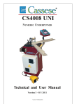
CS 3099 Ultra
NUMERIC UNDERPINNER
Technical and User
Manual
Version 2 - 11 / 2001
Sté CASSESE , Zone Industrielle - Verneuil l’Etang - 77390 - FRANCE
Tel : + 33.1.64-42-49-71 / Fax : +33.1.64-42-58-94
Web: www.cassese.com / e-Mail: [email protected]
Cassese / Communication
GETTING FAMILIAR WITH YOUR CS 3099 Ultra
Fig 1
REBATE CLAMP
PRESSURE
STOP & START ADJUSTER TOP PRESSER
BUTTON
SPEED
ADJUSTER
STAPLING
BUTTON (DA)
TOP PRESSER ( Pr )
BACK FENCES
PRE-CLAMPING
LEVER ( PG )
G1 FIXED CLAMP
G2 PIVOTING CLAMP
COMPRESSED
AIR VALVE
MANOMETER
DIGITAL TOUCHSCREEN KEYBOARD
TOP PRESSER
PLUNGER
REBATE CLAMP
( G1 & G2 )
BACKFENCES INCLINATION ADJUSTERS
( RI )
ASSEMBLY ANGLE ADJUSTER ( AS )
SLIDING TABLE ( TC )
B1
SLIDING TABLE
B2
LOCKING LEVER ( MB )
Fig 2
WIRE FOR WEDGE
PUSHER SPRING ( F )
SELECTION OF VALUE BY REPEATED PUSHES
RECORD OF ANY NUMERIC VALUE
TOUCH
SCREEN
SYMBOLIC
BUTTONS
ENTER
CLR
RETURN
RECORD OF ALL VALUES ON A SCREEN
TO CLEAR A VALUE
TO RETURN TO PRECEDENT MENU
or “NEXT” TO GO TO NEXT MENUE
?
HELP (EXPLANATIONS)
A
FUNCTION PARAMETERS
IMPORTANT
On MAIN MENU, press:
MAINTENANCE / on INPUTS screen, press
/ then
again / you have reached the screen of machine’s function
again / CAUTION message, press
PARAMETERS
1 2 3
4 5 6
7 8 9
0 CLR
LANGUAGE
MANUAL MODE
ENGLISH
MINIMUM
EXECUTE IN
PREVIOUS
WEDGES OFFSET 0000
PIN CODE
0000
RETURN
LANGUAGE : You can change the active language by pressing on LANGUAGE.
MANUAL MODE
While executing (assembling frames), your CS 3099 Ultra can work on 3 different manual modes:
MINIMUM (MANUAL): the foot pedal pushed + by pushing the stapling button once, the whole joining cycle is
carried out.
MEDIUM
: by pushing the stapling button, all the wedges of only one stapling position are inserted.
MAXIMUM (MANUAL): The cycle is fully detailed; the stapling button must be pushed each time to insert one
wedge.
EXECUTE IN:
Here, by pressing on the key, you can preset the PRIORITY Execution Mode of the machine amongst 3 modes:
MANUAL : Machine proposes you Manual execution in priority. See manual modes above.
AUTOMATIC: When executing, the machine proposes Automatic Mode in priority. In automatic mode, pushing on
foot pedal, the whole assembly cycle is carried out.
PREVIOUS: Machine proposes you the last mode used when executing; may be manual or Automatic.
OTHER PARAMETERS:
Pushing key on screen, each parameter can be modified.
Values in WEDGE OFFSET are factory set for each machine; do not modify them, unless requested by your supplier
of CASSESE products.
PINCODE
Your CS 3099 Ultra is equipped with 2 pin codes that prevent the operator to access to certain menus:
CODE 2802 disactivates both access to JOINING FILE and to EXECUTE DIRECTLY so no article can be cancelled, modified or added to the memory. Nor can be joined any moulding that is not in File.
CODE 2803 blocks the access to EXECUTE DIRECTLY only, so that no moulding that is not in file can be assembled or no mouldings in file can be assembled with modifications of its joining parameters.
To activate a pin code, enter it and validate by pressing
.
To cancel a pin code, enter it again and validate by pressing
.
RETURN brings you back to MAIN MENU of the machine.
B
PROGRAMME OF CS 3099 Ultra
INTRODUCTION SCREEN
MAIN MENU
CREATE
JOINING FILE
MODIFY
MAINTENANCE
ERASE
INPUTS
LIST OF ARTICLES
OUTPUTS
VISUAL MODE
EXECUTE
PARAMETERS
EXECUTE FILE
EXECUTE DIRECTLY
HAMMER CHANGE
MOULDING PARAMETERS
LANGUAGE
MANUAL MODE
SPACER
EXECUTE IN
AUTOMATIC / MANUAL
WEDGE OFFSET
PINCODE
45°
30°
22.5°
C
CS 3099 ULTRA AIR LINE FITTINGS
Advised way of fitting :
USA
STANDARD
Male Connector
on Machine
Z 675
Z 675
quick release (Q/R)
female air connector
Z 749
Q/R US male
connector
Standard hose
connector
Z 701
Z 556
AIR SOURCE (compressor)
CONNECTING TO COMPRESSED AIR
QR
Open the access trap of the machine with the trapdoor
key supplied. See above for the air fittings supplied with
machine accessories. Before connecting the compressed
air arrival hose to these fittings, screw into the quick release female connector QR EITHER the standard hose
connector OR the US male connector. Then, connect it to
an air source of 7 bars (100 psi).
D
CONTENTS
IMPORTANT
- GETTING FAMILIAR WITH YOUR CS 3099 Ultra
- TOUCH SCREEN SYMBOLIC BUTTONS
- FUNCTION PARAMETERS
- PROGRAMME OF CS 3099 Ultra
- AIR LINE FITTINGS
- CONNECTING TO COMPRESSED AIR SUPPLY
INTRODUCTION
- ACCESSORIES
- SPECIFICATIONS
- OPTIONS
- GUARANTEE
PAGES
A
A
B
C
D
D
1
INSTALLATION
- PREPARATION
- CONNECTION TO ELECTRICITY
- FITTING THE SILENCER ( MUFFER)
2
2
2
PUTTING INTO OPERATION
3
ADJUSTMENTS - CHOICE OF A TOP PRESSER
- USE OF THE SET OF SPACER BARS
- ADJUSTING THE SLIDING TABLE
- ADJUSTING THE INCLINATION OF THE FENCES
- ADJUSTING THE ASSEMBLY ANGLE
4
4
5
5
6
USE
- MEANS OF ASSEMBLY
- LOADING & CHANGING THE WEDGE CARTRIDGE
- SELECTION OF STAPLING POSITIONS
- PREPARATION FOR PRESET RECORDING
- PRESET RECORDING
- EXECUTION (JOINING) OF AN ARTICLE
- PRESET RECORDING OF AN ARTICLE WITH MULTIPLE
(UP TO 6) STAPLING POSITIONS
- MODIFICATION & CANCELLATION OF AN ARTICLE
- VISUAL MODE
- SCREEN MESSAGES – FAULTS AND REMEDIES
MAINTENANCE
- LUBRICATION / CLEARING OF A WEDGE HALF
ENGAGED IN THE MACHINE
- IN CASE OF HAMMER JAMMING (wedge driver blade)
- PARTS LISTS & DRAWINGS
7
7
7
8
8 - 9
9 - 10 - 11
11 - 12
13
14
15
16
16
17 - 18
INTRODUCTION
You have just bought a CS 3099 Ultra numeric frame joining machine, so we congratulate on your sensible choice and
thank you for your trust in Cassese products.
The CS 3099 Ultra benefits from the experience of the joining machines that brought Cassese a certain reputation. It
makes it possible to join wooden mouldings of all profiles (patent n° 7522814).
The CS 3099 Ultra is designed to allow the operator to move all around the machine.
The joining operation is carried out by using metal wedges especially designed to perform a tight join. These wedges
come in throw-away plastic cartridges, without glue, individually lubricated and rust-protected for the toughest challenges.
IMPORTANT : Do not use any other wedge cartridges but genuine Cassese cartridges.
(registered mark CS).
ACCESSORIES SUPPLIED WITH THE MACHINE
The CS 3099 comes with a cardboard accessory box that contains:
1 Key for machine door
1 triangle support with 1 black rubber triangle (hard) +1 white triangle (soft)
1 extra long triangle support (for fast work with very small profiles)
1 round rubber support with - according to mouldings shape and height:
2 green rubber ends for hardwood types (1 short and 1 long)
2 yellow rubber ends for soft wood types (1 short and 1 long)
Spacer bars for small mouldings / 3 allen keys for hexagonal nuts (# 2.5 – 3 –5mm)
1 Wedge pusher tool / 1 spare hammer (wedge driver blade) / 1 tube of grease
1 Air exhaust Silencer (muffler) / 1 quick release female air connector for the male one that is on machine / 1
quick release US male connector / 1 hose connector /
2 wires to connect machine to mains supply (one with standard + one with US plug).
TECHNICAL SPECIFICATIONS OF CS 3099 ULTRA
Moulding width : Minimum 3 mm (1/8”) - maximum width : 130 mm (5¼”)
Moulding height : Minimum 5 mm (3/16”) – maximum 90 mm (3¾”)
Minimum dimensions of a frame : 85 mm x 85 mm visibly (3½” x 3½”)
Wedge sizes in cartridges of 275 pieces : 5, 7, 10, 12 and 15 mm. On special order size #4 and #3 (1/8”) are also
available for assembly of slips (filets).
Two wedge types : for soft and for hardwoods. Don’t use Hardwood wedges on softwoods.
Machine weight : 105 kg (233 lbs)
Dimensions : Width 48 cm (19”) x Depth 44 cm (17½”) (without optional rotating extension table) x Height 114
cm (45”)
Power supply : Electric : 220 V - 110 V single phased, 50/60Hz, Consumption 500 W.
Pneumatic : compressed air 7 bar (100 psi). Average consumption: 5 liters / cycle.
Air preparation : pressure reducing valve + manometer, connecting pipe, inside diameter 8 mm.
-
OPTIONS
Independent rotating table, diameter 1300 mm (50¼”) to make the handling of large frames easier (frame di
mensions not exceeding table diameter). Cassese Item # Z.3074.
Set of furniture clamps to join mouldings without rebate and/or small frames. Item # Z.2763.
2 other extra long round rubber supports for faster work on small profiles : +15 mm (+5/8”) longer support :
Item # Z.7948 // +30 mm (+1¼”) longer support : item # Z.7949
Angle inserts for 6-sided frames (Item Z.3204), for 8-sided (Z.3203) or other forms on request.
Bar code scanner system (item Z.3471).
File Memory management + Storing + bar code creation software on PC (item Z.4999).
GUARANTEE
One year guarantee for parts and labour against manufacturing defects. Wear parts and those damaged as a result of
non appliance with the instructions of the present manual are excluded from the guarantee.
1
INSTALLATION
Wood piece
Mtc
Tc
To avoid damages due to vibrations during transit,
your CS 3099 Ultra comes with a piece of wood
located between the wedge distributor and the sliding table Tc. To remove it, loosen Mtc (Sliding table locking lever) and slide the table Tc backwards.
Reassemble the four feet of the machine supplied
among accessories and adjust the level of the machine
to your floor so that the machine vibrates or moves as
little as possible which is the most important reason
for fast mechanical ageing of all equipment.
Wedge distributor
CONNECTING TO ELECTRICITY
Your machine comes with the voltage selector (S) in position 220-240 V. If your local tension
is 110 V, just follow the instructions below and connect machine to 220 or 110 V single phased
grounded power socket, either with the cable supplied with standard plug or with the one
E end.
that has a US plug at its
Voltage needed
To change machine to 110 V,
with a flat screwdriver, remove from underneath the selector S, and turn it upside down.
Push it back in. The voltage needed by machine
is marked in left, upper corner of selector S.
S
FITTING THE SILENCER (MUFFLER)
Screw the silencer on machine’s frame into nut E. Put some
grease on the (threaded) screw part of the silencer ; a full tube
of grease is delivered in the accessory box of the machine.
E
2
PUTTING INTO OPERATION
Turn on the compressed air valve. The pressure shown on manometer should be 7 bars.
If your compressor is sending out a higher pressure but the manometer is showing less, increase the pressure at machine’s regulator -where the air arrival is connected.
(Turning) Stop / start button
Manometer
(pressure gauge)
Compressed air valve
Turn the red Start/Stop button so that it comes up to START (ON ) position.
The following introduction screen comes up:
ZONE INDUSTRIELLE - 77390
VERNEUIL L’ETANG - FRANCE
tel : 33164424950 fax: 33164425890
Number of cycles
carried
out by the machine
since day 1.
UNDERPINNER
CS 3099 Ultra
CYCLES : 00000055
Number of wedges
inserted by the machine
since day 1.
WEDGES : 00000082
1/2 METERS : 0000520
VERSCR: 01.01
Distance (in multiples of ½ metres =
2 feet) moved by machine’s wedge
insertion mechanism since day 1.
VERPROG : 01.00
TOUCH THE SCREEN TO CONTINUE
Depending on the quantity of stapling positions for each item, your CS 3099 Ultra can keep in
memory more or less articles.
The more there are stapling positions per item, the smaller becomes the number of items the machine can keep in its File manager. For information,
MAXIMUM ARTICLE (Item or Profile) QUANTITIES & STAPLING POSITIONS PER ITEM
Qty of stapling positions per article
(item or profile)
1
2
3
Qty of items CS 3099 Ultra can memorise in File1500 1200 1000
4
5
6
857 750 660
3
ADJUSTMENTS
SELECTION OF A TOP PRESSER END
Make sure that the distance
between the moulding’s top and
the presser’s bottom is not more
than 50 mm (2”).
PRESSER
50 mm(2’’)
MAXIMUM
MOULDING
If the distance is bigger, use a longer top presser end. For very tall mouldings the round rubber
tips can be also inserted into the top presser bracket without their support to gain capacity in
height.
BLACK TRIANGLE PRESSER
WHITE TRIANGLE PRESSER
GREEN RUBBER TIPS
YELLOW RUBBER TIPS
FOR HARDWOODS mounted on support
FOR SOFTWOODS with a 2.5 mm Allen key
FOR HARDWOODS
1 long and 1 short
FOR SOFTWOODS
1 long and 1 short
Triangle top pressers are good for flat mouldings or for mouldings presenting a flat or horizontal
area to come down on. The round rubber ends are good for complicated forms (uphill, downhill
or reverse mouldings).
USING THE SET OF SPACER BARS
In case you have to join small mouldings with a
smaller height than the fences, you must put the
spacer bars between the mouldings and the fences to
create a distance.
Presser
Moulding
INCORRECT
Fences
Wedge distributor
CORRECT
Set of spacer bars
4
ADJUSTING THE SLIDING TABLE TO THE MOULDING
1) On MAIN MENU, press EXECUTE, then EXECUTE DIRECTLY.., then EXECUTE. The
machine will ask you to PLS ADJUST THE TABLE. Now turn to ON the pre-clamp command
button PG (Fig 1 page A) to make advance slightly the rebate (rabbet) clamp of the machine G1
& G2 (Fig 1).
2) Make sure that the knobs of backfences inclination adjusters RI (Fig 2, page A) are at O
(zero).
3)Standing behind the machine (as seen on Fig.2, page A), put a moulding chop against left hand
fence B1.
4) Move sliding table TC (fig2 pA) forward as far as the moulding comes into contact with the
clamp G1 (fig1, pageA).
5) Tighten the sliding table blocking handle MB (fig2,pA).
6) Now you can turn the pre-clamp button PG to OFF position again.
ADJUSTMENT OF THE INCLINATION OF THE FENCES
ADJUSTMENT KNOBS ( RI ) FOR
THE INCLINATION OF THE FENCES
+
If the corner has an opening on top, turn the two
adjustment buttons (RI) an identical value to the
MINUS (-) (see above picture ) until the opening
disappears when mouldings are clamped.
0
-
If the corner has an opening underneath, turn the
same two adjustment buttons (RI) an identical
value to the PLUS (+) until the opening disappears when mouldings are clamped.
5
ADJUSTMENT OF THE ASSEMBLY ANGLE
If several cutting machines are being used in your production or if you receive your mouldings already cut by your suppliers (chop service), the angles of the mouldings will be slightly different from one cutting machine to the other. The wider the moulding
the more visible will be this angle difference.This is why the joining angle of your CS 3099
Ultra can be adapted to find precisely the cutting angle of your cutting machine.
If the corner is open towards outside, (standing behind the machine) screw in the adjustment screw AS (see picture below ) to correct the fault and check the quality of the angle
by clamping the corner again.
Open Outside
Inside
If the corner is open towards inside, unscrew the same angle adjuster AS to correct the fault
and check the quality of the corner by clamping the mouldings again.
In the event of such a result, check your cutting angle
that is actually bad because under 45°.
Have the angle of your cutting machine corrected, as it
is impossible to make a rectangle frame with angles
smaller than 90°.
( AS ) SETTING SCREW FOR
THE ASSEMBLY ANGLE
6
USE
MEANS OF ASSEMBLY
The joining is performed by using metal wedges, a Cassese invention, designed to ensure very tight corners. Five standard sizes are available : 5, 7,
10, 12 and 15 mm. On special request #3 & 4 are available for slips (filets).
They all come in throw-away cartridges that are colour-coded per size for
easy identification.
Cartridge wedges exist in two versions : NORMAL for soft and normal
timbers and HW for very hard timbers. These hardwood wedges are to be
used only on hardwoods.Your CS 3099 Ultra is designed to use all sizes of
Cassese cartridges without having to change any parts on the machine or
having to adjust anything. For the long term performance and reliability of
your CS 3099 Ultra, only use genuine CASSESE wedge cartridges. Beware of bad quality copies that would cause technical problems and would
age your machine prematurely.
LOADING AND CHANGING THE WEDGE CARTRIDGE ON MACHINE
Pull the wire with ball of the wedge pusher spring F (fig.2, page A) fully out.
If there is a cartridge on machine, holding the wire pulled out, remove it by simply sliding out the
cartridge.
Holding the wire pulled out, put a new cartridge on machine and pay attention that it is fully inserted in the wedge distributor’s window.
Release gently the wire with ball of the wedge pusher spring F.
SELECTION OF STAPLING POSITIONS
The CS 3099 Ultra is designed to join mouldings in 1 to 6 places (positions) with 1 to 9 wedges in
any of those places. In the case of several wedges in the same position, they will penetrate the
wood pushing the previous wedge(s) deeper inside. The selection of the size of wedge to be used
and the number of positions depends on the width and thickness of the moulding to be assembled.
As a general rule, the joining must be carried out as close as possible to the thickest (highest) parts of the
mouldings.
A MINIMUM of 2 mm clearance (approx. 1/8”) above the wedges shall be respected. The harder the wood
timber, the more should be this clearance to prevent the moulding from cracking.
Example
2 mm MINIMUM( approx. 1/8’’)
10mm
2 mm MINIMUM
10mm( 3/8’’)
10mm
12 mm
7
PREPARATION FOR PRESET RECORDING
The highest portion of this moulding
gives the best position for stapling.
Outside of the
moulding
0
Position
Width
The width of the moulding -without the
rebate- and the stapling position (for the
wedge) are measured in millimetres
perpendicularly (at 90°) to and starting from
the outside of the moulding.
The CS 3099 Ultra can keep in memory article numbers that can contain up to 7
numeric digits. (This may be -depending on your choice- your profile or moulding or a
completely new item number.)
RECORDING OF AN ARTICLE
To create an article containing all the assembly data for a type of moulding, on MAIN
MENU, press JOINING FILE key, then CREATE.
CS 3099 Ultra
MAIN MENU
EXECUTE
JOINING FILE
MAINTENANCE
FILES MANAGER
CREATE
MODIFY
ERASE
VISUAL MODE
FREE
MEMORY
6000 / 6000
?
RETURN
8
Every numeric information should be confirmed with the key
the previous information which may be simply O (zero).
.Otherwise the keyboard will keep
STEP 1
-Enter the number on screen (1 to 7 digits) you want
to give to this moulding or profile. In case of mistake,
REFERENCE TO CREATE
press CLR and start again. Confirm with .
0000300
-Page 1 of the Joining parameters comes up.
-RETURN key brings you back to FILE MANAGER
RETURN ?
menu.
STEP 2
1 2 3
REFERENCE 0000300
-Enter the moulding’s width (w/out rebate) in mm,
MOULDIG WIDTH : 015
4 5 6
confirm with
WHITE TRIANGLE
7 8 9
-Pressing the key of top presser types proposed by the
SPACER
0 CLR
machine, leave it on the top presser you want for this
SIZE
5
moulding. Pushing on key SPACER (you will darken
ENTER
RETURN ?
this key), you confirm that you want to use spacer
bars with this profile. By pushing again, you cancel.
1
2
3
1 2 3
Pressing the wedge SIZE key several times, leave it
POSITION
008 000 000
4
5
6
NUMBER
1
0
0
on the size & type you want (Hardwood “HW” or
7 8 9
4
5
6
normal –no mark after size). Press to access to the
POSITION
000 000 000
0 CLR
second screen of joining parameters.
NUMBER
0
0
0
STEP 3 -Enter now the stapling positions (distances
ENTER RETURN
in mm from the back of moulding) and the number of
wedges for each position. Confirm with every time. To move the cursor, use the keys and .
TIP : If you want more than one stapling position, it would be wise to memorise the stapling positions from the smallest value (closest to the back) to the biggest value (closest to the rebate of
moulding); the machine’s programme executing the assembly process exactly in the order memorised (from 1st to 6th position), this would make it work faster and create for the operator a bigger
space to bring the corner out of machine.When all information has been given, press ENTER to
memorise. The machine will propose you to go on Creating new references. RETURN key brings
you back to FILE MANAGER, then to MAIN MENU. On all screens, the ? key provides you some
help and short explanations.
To create an article by VISUAL MODE , see page 14.
JOINING FILES
1 2 3
4 5 6
7 8 9
0 CLR
EXECUTION OF AN ARTICLE (JOINING A FRAME)
EXECUTION MENU
EXECUTE FILE
EXEC. DIRECTLY or LAST JOB
VISUAL MODE
RETURN ?
1
4
REFERENCE TO EXECUTE 7
0000124
0
EXECUTE FILE
2
5
8
3
6
9
CLR
RETURN ?
On MAIN MENU, press EXECUTE. In EXECUTION MENU, there are 3 possibilities:
1) EXECUTE FILE; to assemble a frame with a moulding or profile that is in File memory; enter
the article number and press to confirm. To correct a mistake in moulding number, press CLR and
enter the item number again. RETURN key brings you back to previous menu.
9
Moulding :
Width
:
PLEASE
USE THE BUNG BLACK TRIANGLE
WEDGES SIZE 10 HW WITHOUT
SPACER WITH THIS ARTICLE.
Touch the screen to continue
0000124
018
1
POSITION 005
NUMBER 1
4
POSITION
NOMBER
000
0
EXECUTE
2
3
000
0
000
0
5
000
0
6
000
0
1 2 3
4 5 6
7 8 9
0 CLR
RETURN
The CS 3099 Ultra reminds you the accessories needed –type of top presser end; with or without
spacer bars; which size and type of wedges to be used - to join this moulding in the best way.
Make the necessary changes on machine and load the correct cartridge. Press anywhere on screen
to continue.
A new screen comes up showing the parameters that are preset for this specific moulding. Press
EXECUTE, CS 3099 Ultra invites you to PLS ADJUST THE TABLE (TC on Fig2, page A or
section, page 5). As soon as you turn the pre-clamp command button to OFF position, (fig1 pA), the
machine –or more precisely, its wedge distribution system- will go to the first stapling position.
A new screen comes up proposing you the priority
execution mode preset in the machine’s function paSize 10HW
EXECUTION : MANUAL
rameters; EXECUTION : MANUEL or AUTO1
2
3
POSITION
010
000
000
MATIC: Automatic means that the machine will
SPACER
NUMBER
2
0
0
4
5
6
POSITION
000
000
000
make the whole assembly cycle, just by pushing on
NUMBER
0
0
0
the foot pedal. Manual means that the machine will
45°
RETURN
?
clamp mouldings with foot pedal, then the stapling
button DA (Fig1, page A) must be pushed to insert wedges. (For different manual modes, see section on page B).
MOULDING: 00000124
Moulding Width : 018
BUNG : BLACK TRIANGLE
The machine still allows you to change the execution mode proposed, by just pushing on the same
key.
TIP: When you start with a new moulding or profile, join the first corner in MANUAL mode to adjust
perfectly the backfences, assembly angle etc by clamping the mouldings and seeing the result without
inserting wedges yet. Then for the following corners or frames, change to AUTOMATIC. If all these
chops were cut on the same cutting machine, the machine will give you every time exactly the same result as the first corner.
In the same way, the SPACER key is darkened if spacer bars were needed for this moulding. You can
still decide to change it by pushing simply the same key.
These changes will not affect the article in preset memory of the machine and will be valid only for this
work with this moulding.
45° The machine always proposes a rectangle frame, as the key on execution screen shows that the
machine is currently assembling moulding chops that are cut at 45°. If you want to make 6-sided or 8sided frames with any profile in memory of the machine, just pressing this key to 30° for 6-sided (hexagon) or to 22.5° for 8-sided (octagon), your CS 3099 Ultra will immediately take into account the new
form of the frame and calculate the new stapling positions depending on the initial information in FILE
for this moulding, so that the wedges are inserted exactly to the same places of the moulding.
You need to insert the corresponding angle attachments (available as options, see Options, page 1) between the mouldings and the 90° assembly angle of the machine.
BOTH IN AUTOMATIC and MANUAL MODES OF EXECUTION, THE FOOT PEDAL MUST
REMAIN PUSHED DURING THE WHOLE JOINING CYCLE.
10
For mechanical reasons, the maximum width of mouldings and the closest positions to
the inside of frame are limited as follows for hexagon and octagon frames:
Minimum Distance of Wedge to Rebate Maxi Width of Moulding
OCTAGON
(8-sided)7mm (5/16”)
115mm (4½”) +rebate
HEXAGON
(6-sided)3mm (1/8”)
120mm (4¾”) +rebate
2) EXECUTE DIRECTLY OR LAST JOB
This is the second possibility in the execution menu which calls up the last joining parameters
which have been executed, created or modified. This execution mode is very interesting to be
used in three cases:
- When the same work (or a series in production with the same profile) is to be continued after the machine has been stopped. In this case, the machine will not ask for the accessories
needed, presuming that they are left on the machine since the last assembly job- and will go
immediately to the execution screen.
- As in this case all parameters can be modified without altering them in the file memory, a
moulding in memory can be assembled exceptionally in a different way. For example, when
wedges #10 are needed and you are out of stock of this size, you can use size #5 and put twice
as many wedges in each stapling position.
- When a moulding that is not in file is to be assembled and if you don’t wish to memorise this
moulding. Nevertheless, if this moulding may be assembled again, it is advised to memorise it.
3) EXECUTE IN VISUAL MODE : to join a frame by physically adjusting with a
moulding chop (see page 14) .
PREPARATION AND RECORDING OF AN ARTICLE
WITH MULTIPLE (up to 6) STAPLING POSITIONS
2 mm MINIMUM
approx: 1/8 ‘’
WEDGE
POSITION
2 mm MINIMUM ( approx: 1/8 ‘’)
2 mm MINIMUM ( approx: 1/8 ‘’)
36 mm
16 mm
14 mm
Depending on their width, mouldings can be assembled in up to 6 stapling positions.
The rule of minimum 2mm (1/8”) clearance above the wedges gives us the maximum penetration possibility for each position. This will determine the best wedge size for all the positions and the quantity of wedges to be used in each position.
Advice: To get the best and tightest
corners possible, make sure that
wedges in each position penetrate
and pull together at least 2/3 of the
height in this area.
11
MEASURING THE WIDTH OF MOULDING
The rebate is not
counted.
Advised Chart to fill for each item
ARTICLE Nr
WIDTH
POSITIONS
WEDGE SIZE
121 104 80 63 50 32
130 mm
( mm )
ML
90°
0
0
399
130 mm
32 50 63 80 104 121
TYPE 10 (normal)
NUMBER OF WEDGES 4 3 2 2 2 2
TOP PRESSER
GREEN RUBBER45(= long )
SPACERS
NO
MEASURING THE WEDGE POSITIONS
The width of the moulding not counting the rebate and the positions of the wedges are measured in millimetres, perpendicular to and starting from the outside edge (back) of the moulding.
The stapling points (=positions) are projected perpendicularly onto the 90° line of measurement of the width ML (see above). The measurement of each point starts from the outside
edge.
TIP: If you have drawings of your mouldings on a catalogue, in actual sizes, it will be
much easier to work on drawings and to measure with a metric rule.
Once all the measures have been taken and noted, a table like the one above can be made up for
each profile or moulding, before entry on the screen of the machine.
JOINING FILES
REFERENCE TO CREATE
0000399
1 2 3
4 5 6
7 8 9
0 CLR
RETURN ?
REFERENCE
0000399
1 2 3
MOULDING WIDTH : 130
4 5 6
GREEN RUBBER 45
7 8 9
SPACER
0 CLR
SIZE
10
ENTER RETURN ?
On MAIN MENU, press JOINING FILE, followed by CREATE. Enter the item number,
confirm with .
Enter now the moulding width in mm. Don’t forget to confirm with each numeric information you enter. Press on the key proposing a top presser type until your choice comes up.
Press and darken the SPACER key, if you want to use spacer bars. Otherwise, leave it so.
Press on SIZE until the size and type of wedge you want comes up (out of 10 choices).
Press to continue.
Enter now the stapling positions in mm and
1
2
3
1 2 3
number of wedges for each position. Confirm
POSITION
005 00 00
4
5
6
NUMBER
1
0
0
with every time. To move the cursor, use the
7
8
9
4
5
6
keys and . In case of mistake press CLR.
POSITION
005 00 00
0 CLR
TIP : Although CS 3099 Ultra accepts stapling
NUMBER
1
0
0
positions in any order and would execute the
ENTER RETURN
assembly process exactly in the order memo
rised (from pos.#1 to 6), it would be wise to memorise the stapling positions from the smallest
value (closest to the back) to the biggest value (closest to the rebate of moulding); this would
make it work faster and create for the operator a bigger space to bring the corner out of
machine.When all information has been given, press ENTER to memorise.
12
MODIFICATION OF AN ARTICLE
CS 3099 Ultra
MAIN MENU
FREE
MEMORY
6000 / 6000
CREATE
MODIFY
ERASE
EXECUTE
MAINTENANCE
JOINING FILE
FILES MANAGER
?
VISUAL MODE
RETURN
On MAIN MENU, press JOINING FILE, followed by MODIFY.
JOINING FILES
REFERENCE TO MODIFY
0000325
ARTICLES LIST RETURN
1 2 3
4 5 6
7 8 9
0 CLR
RETURN ?
Enter the item number to be modified.
The articles in file can be seen via the key
ARTICLES LIST.
Confirm the number with to open the file
and to modify it. All parameters of a file
(accessories & joining process) can be modified in the same way as when created. (See
page 8 PRESET RECORDING).
To go from the first page of a file to the second, use . To return from 2nd page to the first,
use .
Once all the modifications have been recorded, press ENTER key to confirm and to memorise
the new data for this article.
Note: If you add stapling positions to a file, the assembly process will be executed in the order of
stapling positions (from the 1st to 6th). This is to say, if you modify a file by adding a 3rd position
between two already existing, it is normal that the machine moves from first to second position,
then only returns half way back to execute the third position.
CANCELLATION OF AN ARTICLE
CS 3099 Ultra
MAIN MENU
EXECUTE
JOINING FILE
MAINTENANCE
FILES MANAGER
CREATE
MODIFY
ERASE
VISUAL MODE
FREE
MEMORY
6000 / 6000
?
RETURN
On MAIN MENU, press JOINING FILE, followed by ERASE.
Enter the item number to be cancelled from
1 2 3
memory.
4 5 6
The articles in file can be seen via the key ARREFERENCE TO ERASE
7 8 9
TICLES LIST. Confirm the number with . Your
0000055
0 CLR
CS 3099 Ultra will still ask you if you are sure to
be willing to cancel this item from memory. ConARTICLES LIST
RETURN ?
firm your decision or Return.
JOINING FILES
13
Visual Mode
(starting from program version 1.02 and screen version 1.02/2.01)
For accuracy, all measures of the 3099 Ultra have to be given in millimetres, i.e. in metric system.
In some countries where imperial system is used –like in North America- this may seem awkward :
With VISUAL MODE, giving measures in metric while memorising or executing a new profile is
brought to minimum, as this mode enables the making up of the file or the execution, just physically with a moulding chop on the machine.
In the MAIN MENU, press either the key
JOINING FILE or EXECUTE .
Next press the key VISUAL MODE.
The following mask then appears:
REFERENCE: 0000302
Moulding width: 047
WHITE TRIANGLE
SPACER
SIZE
VISUAL MODE
1 2 3
4 5 6
7 8 9
0 CLR
RETURN
A reference and moulding width must be entered before you can continue. Enter the reference
number using the numeric keypad and validate using the key
Next press the key
and enter the width of the moulding to be assembled. Validate using the
key
. then press the key
.
Press the WHITE TRIANGLE (top presser) key repeatedly until the appropriate presser can be
selected, then press the key
followed by the key
.
Press the SPACER key to initialize the use of the spaces bars , or if this is not required, press
directly the key
then the key
.
Pressing the wedge SIZE key several times, leave it on the size & type you want (Hardwood
“HW” or normal –no mark after size). Validate by pressing the key
.. Switch to the next
mask by pressing the key:
VISUAL MODE IN PROGRESS
Moulding
width:
047
Now, the wedge distributor & top presser of the
machine go to the closest point to the rebate
4
5
6
clamps. The screen is like here and the machine
Position 000 000 000
is ready to help you decide the wedge positions
Number 0
0
0
EXECUTE & quantity of wedges physically with a moulding
MEM.
- +
chop.
RETURN
1
2
3
Position 047 000 000
Number 0
0
0
(See Fig 1&2, page A) Turn the button PG (pre-clamping command) to ON position and put only
the left hand moulding chop in front of the left back fence B1. Push forward the table TC and
tighten MB. This way, the wedge distributor’s position is visible underneath of the moulding.
Move the plunger using the + and - keys until it reaches the selected stapling point.
Select the number of wedges by pressing the STAPLING button on the keyboard of your CS
3099 Ultra repeatedly until the required number appears. Validate the first position by pressing
the key
.
The second stapling position is initialized. Take the same actions as for the first position ...
At the end you can then either :
Execute your visual settings directly without recording the parameters: EXECUTE or
Store your visual settings as an item recording: MEM. .
14
SCREEN MESSAGES
Your CS 3099 Ultra includes a continuous help function that checks your instructions and which
can be accessed either at your request by pressing ? key on any screen or if there is an incident
or programming mistake. For example:
The Article 0000857
is not in File.
Do you want to create it ?
YES NO
Your CS 3099 Ultra is informing you that the item nr
857 you want to execute is not in Memory File of the
machine and is proposing you to create it immediately…
INCIDENT IN TOP PRESSER’S
COMING DOWN !
ASSEMBLY PROCESS FINISHED
Either too big distance between top presser
and mouldings (more than 50mm=2”) or
top presser coming down too slowly.
RELEASE THE FOOT PEDAL, DON’T PUSH
THE STAPLING BUTTON ANY MORE AND
REMOVE THE MOULDINGS.
Solutions to operation faults and advice messages on screen help the operator during all the
steps of the CS 3099 Ultra’s function.
INSUFFICIENT PRESSURE ALARM !
There is not enough air pressure for the machine
to work normally. Check the air arrival. Once
the problem is solved, machine comes back in
Main Menu.
WARNING !
CLAMP SAFETY ACTIVATED !
EITHER NO MOULDINGS ON THE MACHINE
OR TABLE BADLY ADJUSTED.
Your CS 3099 Ultra cannot function without compressed air. This message will come up also, if the air
pressure comes down below 5 bars (70 psi), as at this
moment the machine does not have the power needed
to insert or to stack wedges in every kind of mouldings, especially hardwoods. Therefore instead of joining badly and wasting mouldings, it will ask for
higher pressure. Check if your compressor or the air
arrival is OK.
The CS 3099 Ultra is equipped with a sensor that
checks if the machine is actually clamping mouldings
and prevents the machine from inserting wedges if this
is not the case.
This message may appear:
-When one of the mouldings is missing on the machine
-If the sliding table is badly adjusted or simply not
locked well enough, making the machine unable to
clamp well
-If the mouldings are too soft, too powerful clamp
pressure may also result in this message; decrease the
clamp pressure at the adjuster next to the screen.
15
MAINTENANCE
BEFORE ANY INTERVENTION, UNPLUG THE POWER SUPPLY AND CLOSE THE AIR VALVE.
Starting from program version 1.02 and screen version 1.02/2.01. After every 50000 wedges inserted by the
machine, the following screen will come up each time you turn-on the machine.
PLEASE CARRY OUT PREVENTIVE
MAINTENANCE.
CHECK INSTRUCTIONS IN
MACHINE’S MANUAL.
50000 wedges inserted.
10000 ½ METERS MOVED
Cycles : 00103659 Wedges : 00535698
40000 ½ METERS MOVED
Touch screen to continue
Every time the machine has inserted 50,000 wedges or has moved
its mechanism a distance of 10,000 times ½ meters (=5 km = about
3 miles), the machine reminds the operator to make a short maintenance to prevent moving parts from wearing and ageing too fast.
This screen does not block the machine but will come up every
time the machine is turned on to start to work, if the maintenance
has not been carried out and the counters have not been reset to
zero.
Pressing on screen or waiting 20 seconds, the screen returns to Main Menu. Please carry out the Maintenance instructed below. Then, to reset the maintenance counters : enter Maintenance on Main Menu, go up
to Parameters screen. To reset wedge counter, enter 5000 in Pincode followed by
For distance counter, enter 5001, followed by
1)PREVENTIVE MAINTENANCE (LUBRICATION)
A) From time to time, remove the wedge distributor (Block H,
see page 17) by loosening its blocking screw. Clean it (by blowing air) without dismantling it. We recommend you to grease the
hammer (wedge driver blade) periodically. To do so, block H must
be removed and a small quantity of grease is then put in the housing of the hammer at the bottom hole of block H.
P
TOOTHED RACK
B) Top clamp plunger (P) must be a little lubricated, using a SAE 20/40 oil. Before turning the machine on again,
make the mechanism move by hand back and forth several times.
2) CLEARING OF A WEDGE STUCK IN THE DISTRIBUTOR
INCIDENT IN
WEDGES
INSERTION ! ! !
STOP THE MACHINE AND CHECK IF THERE
ARE NO WEDGES JAMMED IN WEDGE
DISTRIBUTION BLOCK.
During assembly, one or more wedges may get stuck in
the wedge distributor (block H). The CS 3099 Ultra will
then display the message opposite.
Or if you incidentally lift the top presser plunger when
a wedge cartridge is on machine, this may half engage
a wedge in the distribution mechanism.
WEDGE PUSHER TOOL
Switch off the power and close the air valve.
Try to remove the cartridge that is on machine.
If it resists, use the wedge pusher tool (in
accessory box) to replace the wedge back
in cartridge.
The wedge pusher must not penetrate more
than 6mm (1/4”) into the wedge distributor.
In case of hammer and wedge jamming,
see the following section (3)
6mm( 1/4 ”) MAXIMUM
WEDGE
DISTRIBUTOR
( BLOCK H )
WEDGE EXIT
16
MAINTENANCE
BEFORE ANY INTERVENTION,
UNPLUG THE POWER SUPPLY AND CLOSE THE AIR VALVE.
3 ) IN CASE OF HAMMER & WEDGE JAMMING
WEDGE
DISTRIBUTOR
( BLOCK H)
SCREW POSITIONS
OF BLOCK H
A
D
GF1
SLIDING TABLE
GF2
BLOCKING
SCREW
F
E
B
C
In case of the hammer (wedge driver blade) and a wedge jamming in the wedge distribution block also, the CS 3099 Ultra will display the message INCIDENT IN WEDGES INSERTION. In this case, proceed as follows, after having unplugged the machine from mains
supply and closed the air valve.
-Remove the wedge cartridge from machine.
-With the 3mm allen key (supplied with machine), loosen (no need to remove) the blocking
screw of block H (see above).
-Now lift manually the top presser plunger; this will bring up the block H out of machine.
Remove the block H from machine and check:
1) If there is no wedge or hammer stuck inside it, put it back in machine.
2) If the hammer (like a very long wedge, approx. 8cm (3”) long) is stuck in it, we need to
open the block H to get rid of the old hammer: Use for this the smaller (2.5mm) Allen key
(supplied with machine) and remove the 2 central screws (see above GF1 & GF2) that hold
the fixed (square) guide of Block H in place. Remove the fixed guide completely to free the
old hammer. If still not possible to get rid of the old hammer, remove the 4 corner screws
(A-B-C-D) and open the block H. Two factory set locator pins E & F allow the plates to be
re-positioned precisely again.
Remove the old hammer. Assemble the block H back again.
17
PUTTING A NEW HAMMER
-Put a drop of grease (tube of grease supplied with the machine) in the bottom hole of the
wedge distributor (block H).
-Insert a new hammer into the wedge distributor from the top, with the hole of the hammer
downwards.
-Re-position the wedge distributor in its housing on the machine, with the window towards the
cartridge.
-If the upper end of the new hammer stays out of block H, push it fully in with a piece of
wood or moulding.
-Now, turn on power and air supply to the machine. The introduction screen comes up.
-On the MAIN MENU screen, press MAINTENANCE.
-Then press (next) on the next two screens. You should have reached the following screen:
CAUTION ! ! ! YOU ARE ENTERING THE MACHINE’S
FUNCTION PARAMETERS SCREEN. ANY CHANGE
OF THESE MAY MODIFY THE MACHINE FUNCTIONS.
RETURN
-Press on key which symbolises a hammer.
The machine is ready for hammer change and the following screen comes up:
CHANGE THE HAMMER
Replace the hammer and put a piece of wood or
mouldings under the top presser and press at
the same time
and stapling button
to finish the change process.
RETURN
-Put any of the top presser ends (triangle or round rubber) on the machine and place a
big piece of wood (hardwood is better) on the block H, under the top presser. (The distance between the top presser and the moulding should not exceed 50mm (2”).)
-Now, keeping
-key pressed on the machine, push the stapling (black) button
at the same time; the machine will simulate a wedge insertion so that the new hammer
can take automatically its position in the mechanism.
-Press on RETURN on the screen.
-Now turn off the machine from the power and air supply.
-Tighten the blocking screw of block H (see picture page 16), using the 3mm Allen key
(supplied with machine). No need to tighten too much.
Now the machine is ready to work again.
AFTER ANY INCIDENT IN WEDGES INSERTION, IF THE HAMMER REMAINS IN BLOCK H,
YOU MUST CHANGE IT.
18