1
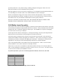
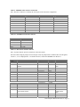
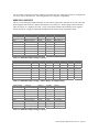
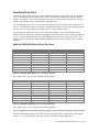
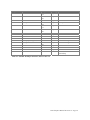
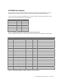
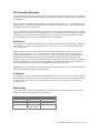
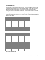
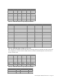
Table 9 - MK68901 Timer Interface Connection
Note: The above connector is normally not used as part of the 2030 tester configuration.
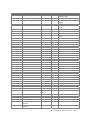
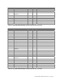
Connector - Pin
P4-1
P4-3
P4-5
P4-7
P4-9
P4-11
P4-13
P4-15
P4-17
P4-19
Signal
Shield
RxD
CTS
GND
TxClock
RxClock
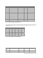
Connector - Pin
P4-2
P4-4
P4-6
P4-8
P4-10
P4-12
P4-14
P4-16
P4-18
P4-20
Signal
TxD
RTS
DSR
DCD
DTR
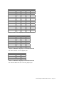
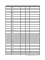
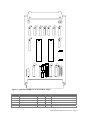
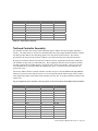
Table 10 - GESMPU14-A RS-232 Connector
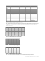
Connector-Pin
P3-1
P3-2
P3-3
P3-4
P3-5
Signal
Reset switch
GND
Abort switch N.C.
Abort switch N.O.
+5 volts
Table 11 - Reset/Abort Switch Connector
Note: J1 jumper must be open for external use of the abort switch.
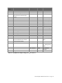
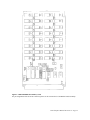
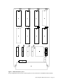
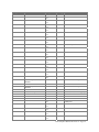
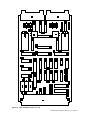
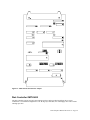
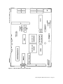
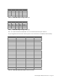
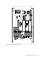
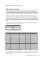
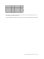
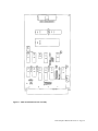
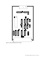
Note that when setting the jumpers on most Gespac cards, the jumper field is numbered like most integrated
circuits i.e., in a U-shaped pattern.. For further reference, consult the GESMPU-14A data sheet.
Jumper
Field
J1
J2
Function
Jumpers
Settings
Result
Local/Remote abort selector
Internal/External Tx and Rx clock
selector
J1-1 to J1-2
J2-1 to J2-10
Closed
Closed
Local abort switch
Internal baud rate
clock
J2-2 to J2-3
J2-8 to J2-9
J2-4 to J2-7
J2-5 to J2-6
J4-1 to J4-18
J4-2 to J4-17
J4-3 to J4-16
J4-4 to J4-15
J4-5 to J4-14
J4-6 to J4-13
J4-7 to J4-12
J4-8 to J4-11
J4-9 to J4-10
J5-1 to J5-10
Closed
Closed
Open
Open
Open
Open
Closed
Closed
Closed
Closed
Closed
Closed
Closed
Open
J5-2 to J5-9
J5-3 to J5-8
Open
Closed
J4
RS-232C modem/terminal selector
J5
EPROM access time selector, bus
system clock selector
DCE (modem)
450 ns access time,
8 MHz system
clock
2030 Computer Manual Revision 1.4 Page 17