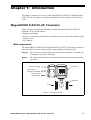
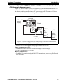
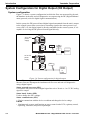
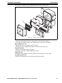
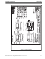
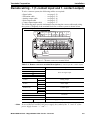
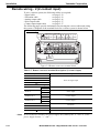
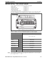
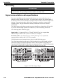
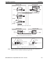
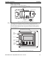
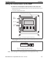
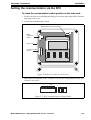
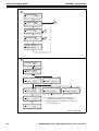
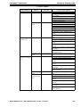
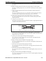
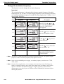
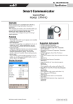
1
MagneW3000 FLEX+/PLUS+ Smart Electromagnetic Flowmeter Converter Model MGG10C-M/P/R/S/T MGG14C-M/P/R User’s Manual CM2-MGG310-2001 1st Edition: Issued in July 2007 2nd Edition: Issued in Dec. 2007 NOTICE While the information in this manual is presented in good faith and believed to be accurate, Yamatake Corporation disclaims any implied warranty of merchantability or fitness for a particular purpose and makes no express warranty except as may be stated in its written agreement with and for its customer. In no event shall Yamatake Corporation be liable to anyone for any indirect, special or consequential damages. This information and specifications in this document are subject to change without notice. Printed in USA - © 2007 by Yamatake Corporation. All rights reserved. Safety About this manual This manual contains information and warnings that must be observed to keep the model MGG10C/MGG14C MagneW3000 FLEX+/PLUS+ Flowmeter operating safely. Correct installation, correct operation and regular maintenance are essential to ensure safety while using this device. For the correct and safe use of this flowmeter, it is essential that both operating and service personnel follow generally accepted safety procedures in addition to the safety precautions specified in this manual. The following symbols are used in this manual to alert you to possible hazards: WARNING Denotes a potentially hazardous situation which, if not avoided could result in death or serious injury. CAUTION Denotes a potentially hazardous situation which, if not avoided could result in minor injury or damage to device. Safety messages Carefully read this section before installing or operating this device. WARNING ELECTRIC SHOCK HAZARD! Turn the power supply OFF before opening the converter cover. CAUTION Switch the control equipment to manual control before terminating flowmeter operation and shutting off the output to the control equipment. This action prevents the power shut-off from directly affecting the control equipment. Model MGG10C/14C - MagneW3000 FLEX+/PLUS+ Converter i Safety Yamatake Corporation CAUTION Install the flowmeter in a location with an ambient temperature of -25 °C to 60 °C (-13 °F to 140 °F) and an ambient humidity of 5 to 100% RH to prevent equipment malfunction or output errors. CAUTION Do not install the flowmeter near high-current power lines, motors or transformers to prevent damage from electromagnetic induction, which can cause equipment malfunction or output errors. CAUTION Do not install the flowmeter in a location subject to direct sunlight, wind, rain, severe vibration, or in a highly corrosive atmosphere. The converter and detector can be damaged. CAUTION Be sure to ground the welding power transformer when welding near the flowmeter to avoid output errors. CAUTION DO NOT use the flowmeter to ground a welder. It can damage the flowmeter. ii Model MGG10C/14C - MagneW3000 FLEX+/PLUS+ Converter Yamatake Corporation Safety MagneW3000 FLEX+/PLUS+ Electromagnetic Flowmeter CE Conformity Supplement CE CONFORMITY: This product is in conformity with the protection requirements of the following European Council Directive: 89/336/EEC, the EMC Directive and 73/ 23/EEC, Low Voltage Directive. Conformity of this product with any other "CE Mark" Directive(s) shall not be assumed. EMC Directive/Standard PC Conformity Notes ELECTROMAGNETIC COMPATIBILITY: 89/336 EEC, EMC Directive EMISSIONS: EN 61326-1997+A1:1998+A2:2001+A3:2003 classA Electrical equipment for measurement, control and laboratory use CISPR 16-1-1999,CISPR 16-2-1996, Group 1, Class A, Industrial Control Equipment, 150 KHz-1000 MHz 0.15MHz-0.5MHz quasi-peak limit 79dB (uV/m) at 10 m average limits 66dB (uV/m) at 10 m 0.5MHz-30MHz quasi-peak limit 73dB (uV/m) at 10 m average limits 60dB (uV/m) at 10 m 30MHz-230MHz quasi-peak limit 40dB (uV/m) at 10 m 230MHz-1000MHz quasi-peak limit 47dB (uV/m) at 10 m IMMUNITY: EN 61326-1997+A1:1998+A2:2001+A3:2003 AnnexA, Electrical equipment for measurement, control and laboratory use, Industrial locations PERFORMANCE: Unless otherwise noted, the performance of this product, at the specified levels of electromagnetic interference, is within the specifications for "Performance Under Rated Conditions," 1 EN 61000-4-2-1995+A1:1998+A2:2001 (IEC 1000-4-2-1995), ESD, Electrostatic Discharge B ±4 kV Contact B ±8 kV Air EN 61000-4-3-2002+A1:2002(IEC 1000-4-3-1995), Radiated RF Fields, 80 -1000 MHz A 10 V/m 1kHz,AM80% 1 EN 61000-4-4-1995+A1:1995+A2:2001 (IEC 1000-4-4-1995), Electrical Fast Transients/Burst A ±2 kV AC Power ±1 kV I/O signal/control 1 EN 61000-4-5-1995+A1:2001 (IEC 61000-4-5-1995) Surge B ±1kV Line to line: Power Lines ±2kV Line to ground: Power Lines ±1kV Line to ground: I/O signal/control Lines 1 EN 61000-4-6-1996+A1:2001 (IEC 61000-4-6-1996) Conducted Radio-frequency, 150 KHz - 80 MHz A 3V 1 EN 61000-4-8-1993+A1:2001(IEC 61000-4-8-1993) Power frequency magnetic field A 30A/m 50Hz 1 EN 61000-4-11-1994+A1:2001 (IEC 61000-4-11-1994) Voltagr Dip/short iterrruptions B 0.5cycle,each polarity/100% NOTES: PC = 1. Performance Criteria Twist pair cables required for all I/O interface circuits. In case of remote model two core double shield cable in metal conduit pipe required for the input line in connection with detector. Conformity LV Directive LOW VOLTAGE DIRECTIVE: 73/23/EEC EN 61010-1:2001(IEC61010-1:2001), Safety requirements for electrical equipment for measurement, control and laboratory use Part 1: General requirements Model MGG10C/14C - MagneW3000 FLEX+/PLUS+ Converter iii Safety Yamatake Corporation MagneW3000 FLEX+/PLUS+ Electromagnetic Flowmeter Documentation Supplement 1. Mains supply The symbol for a.c. or d.c. on the name plate is as follows: for a.c. power supply for d.c. power supply 2. Fuse marking The fuse cannot be replaced by the operator. Fuse rating and electric characteristics are as follows: Fuse rating: Voltage 250V Current 3A Manufacturer type:239003 (LITTEL FUSE) 3. Grounding (Earthing) Protective grounding (earthing) should be connected as shown in Operator's Manual. The MagneW3000 FLEX+/PLUS+ has protective grounding (earthing) terminals in the terminal box and on the external surface of its casing (see figure). External External Internal Remote models Internal Integral models An external switch or circuit-breaker must be installed near the MgneW3000 FLEX+/ PLUS+ on the power line. 4. Equipment operation iv Power line is connected to commercial power. The terminal cover must not be opened when power is on. Model MGG10C/14C - MagneW3000 FLEX+/PLUS+ Converter Table of Contents Chapter 1: Introduction MagneW3000 FLEX+/PLUS+ Flowmeter..................................................................... 1-1 Main components ........................................................................................................... 1-1 Analog output and digital output .................................................................................. 1-3 System configuration for analog output (4 to 20 mA DC output) ................................. 1-4 System configuration WITHOUT the communication function........................................ 1-5 System configuration WITH the HART communication function with the internal power supply ............................................................................................................................. 1-6 System configuration WITH the SFC or HART communication function with the external power supply................................................................................................................... 1-7 System Configuration for Digital Output (DE Output) .................................................. 1-8 System configuration ...................................................................................................... 1-8 Approval of this Device ................................................................................................ 1-10 Chapter 2: Installation Site selection ............................................................................................................... 2-1 Unpacking and storage................................................................................................ 2-2 Installation options ....................................................................................................... 2-3 Changing the orientation of the converter....................................................................... 2-4 Wiring .......................................................................................................................... 2-5 Integral wiring - 1 (1-contact input and 1- contact output) ........................................... 2-6 Integral wiring - 2 (2-contact input) .............................................................................. 2-7 Integral wiring - 3 (2-contact output) ............................................................................ 2-8 Remote wiring - 1 (1-contact input and 1- contact output)........................................... 2-9 Remote wiring - 2 (2-contact input) ............................................................................. 2-10 Remote wiring - 3 (2-contact output) ........................................................................... 2-11 Grounding ....................................................................................................................... 2-12 Signal and excitation cable specifications ...................................................................... 2-12 Signal and excitation cable wiring ............................................................................... 2-14 Wiring cable................................................................................................................. 2-15 Wiring .......................................................................................................................... 2-16 Setting write protection ................................................................................................ 2-19 Setting the communication via the HART .................................................................... 2-21 Setting the empty detection function ........................................................................... 2-22 Setting the communication via the SFC ...................................................................... 2-23 Connecting power........................................................................................................ 2-24 Chapter 3: Operation Start-up........................................................................................................................ 3-1 Shut down.................................................................................................................... 3-1 Using the display panel ............................................................................................... 3-2 Using the infrared touch sensor keys ............................................................................. 3-3 The following table is a summary of the functions of each of the keys........................ 3-4 Chapter 4: Using the display panel About modes ............................................................................................................... 4-1 MEASURING MODE ................................................................................................... 4-4 LCD display flow .......................................................................................................... 4-5 Entering BASIC SETUP MODE................................................................................... 4-11 Table of Contents Setting the TAG NO..................................................................................................... 4-12 Default setting ...................................................................................................... 4-12 Setting range ........................................................................................................ 4-12 Damping time constant ................................................................................................... 4-13 Default setting ...................................................................................................... 4-13 Setting range ........................................................................................................ 4-13 Auto zero ........................................................................................................................ 4-14 Flow counter - Reset value ............................................................................................. 4-16 Flow counter - Resetting................................................................................................. 4-17 Detector data .................................................................................................................. 4-18 Default setting ...................................................................................................... 4-18 Setting the Number of Dummy Detectors ....................................................................... 4-20 Default setting ...................................................................................................... 4-20 Setting range ........................................................................................................ 4-20 Flow rate range............................................................................................................... 4-21 Setting range ........................................................................................................ 4-21 Flow rate indication......................................................................................................... 4-22 Default setting ...................................................................................................... 4-22 Setting range ........................................................................................................ 4-22 Entering ENGINEERING / ADVANCED / MAINTENANCE MODE ................................ 4-23 Entering ENGINEERING MODE .......................................................................... 4-23 Entering ADVANCED MODE ............................................................................... 4-23 Entering MAINTENANCE MODE ......................................................................... 4-24 Selecting functions.......................................................................................................... 4-25 Relations for setting function FXXXX.............................................................................. 4-27 Range functions............................................................................................................. 4-30 Single range ......................................................................................................... 4-30 Normal direction automatic dual range................................................................. 4-31 Normal direction, external switching dual range................................................... 4-32 Normal/reverse automatic switching range .......................................................... 4-33 [Built-in counter function] ...................................................................................... 4-35 [Contact input function]......................................................................................... 4-36 [Contact output function] ...................................................................................... 4-37 Flow rate range .................................................................................................... 4-40 Setting range ........................................................................................................ 4-40 Setting hysteresis ................................................................................................. 4-42 Selecting the current output method for dual range ............................................. 4-43 Setting / Changing the preset value of the built-in flow counter...................................... 4-44 Specific gravity ..................................................................................................... 4-45 Pulse weight ......................................................................................................... 4-46 Setting the pulse width ......................................................................................... 4-47 Setting high and low limit alarms .......................................................................... 4-49 Setting a 2-stage flow rate alarm.......................................................................... 4-50 Selecting fail-safe mode for the analog output ............................................................... 4-52 Default setting ...................................................................................................... 4-52 Setting range ........................................................................................................ 4-52 Selecting fail-safe mode for the pulse output.................................................................. 4-53 Default setting ...................................................................................................... 4-53 Setting range ........................................................................................................ 4-53 Setting the contact output status .......................................................................... 4-54 Damping time constant ................................................................................................... 4-56 Default setting ...................................................................................................... 4-56 Setting range ........................................................................................................ 4-56 Table of Contents Manual zeroing ............................................................................................................... 4-57 Important .............................................................................................................. 4-57 How to set ............................................................................................................ 4-57 Setting moving average .................................................................................................. 4-58 Default setting ...................................................................................................... 4-58 Setting range ........................................................................................................ 4-58 Auto spike cut function.................................................................................................... 4-60 Default setting ...................................................................................................... 4-60 Manual spike cut function ............................................................................................... 4-61 Default setting ...................................................................................................... 4-61 Setting range ........................................................................................................ 4-61 Coefficient of compensation ................................................................................. 4-62 Setting the drop-out .............................................................................................. 4-63 Setting the low flow cut......................................................................................... 4-64 Setting decimal place ........................................................................................... 4-65 Change the excitation frequency .......................................................................... 4-66 Setting the analog output limit .............................................................................. 4-67 Change the flow direction ..................................................................................... 4-68 Error history check/clear....................................................................................... 4-69 Chapter 5: Maintenance and Troubleshooting Function check ............................................................................................................ 5-2 Input and output signal loop check ................................................................................. 5-2 Analog output check .................................................................................................... 5-3 Default setting ...................................................................................................... 5-3 Setting range ........................................................................................................ 5-3 Pulse output check ...................................................................................................... 5-4 Default setting ...................................................................................................... 5-4 Setting range ........................................................................................................ 5-4 Contact input/output loop check ..................................................................................... 5-5 Default setting ...................................................................................................... 5-5 Setting range ........................................................................................................ 5-5 Excitation current check.................................................................................................. 5-8 Simulated signal by the calibrator................................................................................... 5-9 Preparation ........................................................................................................... 5-9 Troubleshooting ........................................................................................................... 5-10 Errors at startup ........................................................................................................... 5-11 Operation errors .......................................................................................................... 5-12 Error messages ........................................................................................................... 5-13 Error codes for critical problems ..................................................................................... 5-13 Error codes for non-critical problems.............................................................................. 5-14 Safety precautions ....................................................................................................... 5-15 Operating precautions .................................................................................................... 5-15 Examples of symbol........................................................................................................ 5-15 Structure and functions of SFC ............................................................................ 5-16 List of Figures Figure 1-1 Figure 1-2 Figure 1-3 Figure 1-4 Figure 1-5 Figure 1-6 Figure 1-7 Figure 1-8 Figure 2-1 Figure 2-2 Figure 2-3 Figure 2-4 Figure 2-5 Figure 2-6 Figure 2-7 Figure 2-8 Figure 2-9 Figure 2-10 Figure 2-11 Figure 2-12 Figure 2-13 Figure 2-14 Figure 2-15 Figure 2-16 Figure 2-17 Figure 2-18 Figure 2-19 Figure 2-20 Figure 2-21 Figure 2-22 Figure 2-23 Figure 2-24 Figure 2-25 Figure 2-26 Figure 2-27 Figure 2-28 Figure 3-1 Figure 3-2 Figure 3-3 Figure 3-4 Figure 4-1 Figure 4-2 Figure 4-3 Figure 4-4 Figure 4-5 Integral System ................................................................................................. 1-1 Remote System ................................................................................................. 1-2 System configuration of analog output WITHOUT communication function. 1-5 System configuration of with the HART communication with internal power supply .......................................................................................................................... 1-6 System configuration for analog output WITH the communication function (example setup)................................................................................................. 1-7 System configuration for digital output............................................................ 1-8 Parts of the converter ........................................................................................ 1-9 System configuration ........................................................................................ 1-11 Integral installation ........................................................................................... 2-3 Wall mounted remote installation..................................................................... 2-3 Pipe mounted remote installation ..................................................................... 2-4 Integral converter terminal block...................................................................... 2-6 Integral converter terminal block...................................................................... 2-7 Integral converter terminal block...................................................................... 2-8 Remote converter terminal block...................................................................... 2-9 Remote converter terminal block...................................................................... 2-10 Remote converter terminal block...................................................................... 2-11 Cable usage ranges ........................................................................................... 2-12 Signal Cable Dimensions.................................................................................. 2-13 Excitation Cable Dimensions ........................................................................... 2-13 Signal and excitation cable construction .......................................................... 2-13 Detector to converter wiring diagram............................................................... 2-14 Wiring diagram for current output.................................................................... 2-16 Wiring diagram for pulse output....................................................................... 2-17 Switch locations on main card.......................................................................... 2-17 Wiring diagram for contact input ..................................................................... 2-18 Wiring diagram for contact output ................................................................... 2-18 Switch locations on main card.......................................................................... 2-20 Write protection switch positions ..................................................................... 2-20 Switch locations on main card.......................................................................... 2-21 HART communication switch positions........................................................... 2-21 Switch locations on main card.......................................................................... 2-22 Empty detection function switch positions....................................................... 2-22 Switch locations on main card.......................................................................... 2-23 SFC communication switch positions .............................................................. 2-23 Name plate ........................................................................................................ 2-24 Start-up display................................................................................................. 3-1 Display panel .................................................................................................... 3-2 Touch sensor keys............................................................................................. 3-3 Using the touch sensor keys ............................................................................. 3-3 Single range ...................................................................................................... 4-30 Normal direction automatic dual range ............................................................ 4-31 Normal/reverse automatic switching range ...................................................... 4-33 2-stage flow rate alarm output .......................................................................... 4-39 Selecting the current output method for dual range.......................................... 4-43 List of Tables Table 2-1 Table 2-2 Table 2-3 Table 2-4 Table 2-5 Table 2-6 Table 2-7 Table 3-1 Table 3-2 Table 4-1 Table 4-2 Table 5-1 Table 5-2 Table 5-3 Table 5-4 Remote converter terminal descriptions (1-contact input & 1-contact output) ... 2-6 Remote converter terminal descriptions (2-contact input)................................... 2-7 Remote converter terminal descriptions (2-contact output)................................. 2-8 Remote converter terminal descriptions (1-contact input & 1-contact output) ... 2-9 Remote converter terminal descriptions (2-contact input)................................... 2-10 Remote converter terminal descriptions (2-contact output)................................. 2-11 Write Protection Levels ....................................................................................... 2-19 Touch Sensor key Functions ................................................................................ 3-4 Default settings .................................................................................................... 3-5 Mode functions .................................................................................................... 4-2 Output selection ................................................................................................... 4-37 Startup Errors ....................................................................................................... 5-11 Operation Errors................................................................................................... 5-12 Critical Errors....................................................................................................... 5-13 Non-critical .......................................................................................................... 5-14 List of Tables Chapter 1: Introduction This chapter contains an overview of the model MGG10C/MGG14C MagneW3000 FLEX+/PLUS+ Flowmeter. It provides definitions for all the major parts of the converter. MagneW3000 FLEX+/PLUS+ Flowmeter Thank you for purchasing the Yamatake Corporation model MGG10C/MGG14C Flowmeter. This system features: • Digital panel display • Intuitive, versatile operator interface with large characters and backlit liquid crystal display (LCD) • I/O Capacity Main components The model MGG10C/MGG14C MagneW3000 FLEX+/PLUS+ Flowmeter consists of a detector and a converter which operate on the principles of Faraday’s law. Integral - The converter is mounted directly on the detector and they are installed as an integrated unit on the fluid pipe. Remote - The converter and detector are installed separately and connected together via cables Converter AC power supply Pulse output Contact input/output Analog output Digital output Detector Fluid Figure 1-1 Integral System Model MGG10C/14C - MagneW3000 FLEX+/PLUS+ Converter 1-1 Introduction Yamatake Corporation Converter Flow signal input AC power supply ly Pulse output Contact input/output ut Dedicated cable Detector Analog output/ Digital output Excitation output Fluid Figure 1-2 Remote System 1-2 Model MGG10C/14C - MagneW3000 FLEX+/PLUS+ Converter Yamatake Corporation Introduction Analog output and digital output Introduction The choice of either an analog output or digital output system configuration depends on whether or not you want to use the digitally enhanced (DE) communication mode. Analog output (4 to 20 mA DC output) In analog mode, the flowmeter sends the instantaneous flow rate as a proportional 4 to 20 mA output signal to a controller or a recorder in the control system. Digital output (DE output) A flowmeter in the DE mode can communicate in a direct digital fashion with Yamatake or Honeywell DCS system. The digital signal can include flow rate, flowmeter database, and self-diagnostics. Switching output mode The analog/digital output mode is selectable. Model MGG10C/14C - MagneW3000 FLEX+/PLUS+ Converter 1-3 Introduction Yamatake Corporation System configuration for analog output (4 to 20 mA DC output) Introduction In the analog mode, the flowmeter can be configured with or without SFC communciations. WITHOUT the communication function The DC power supply that transmits the analog output, when the flowmeter is used without SFC communications, is built into the product. The analog output signal is transmitted directly to the host control system. • Analog output range: • Resistive load: 0.8 to 22.4 mA (-20 to +115%) 0 to 600 Ω WITH HART communication function The DC power supply that transmits the analog output and HART communication, when the flowmeter is used with the HART communications, is built into the product. • Analog output range: • Resistive load: 3.2 to 22.4 mA (-5 to +115%) 0 to 600 Ω WITH the communication function (SFC or HART) When the flowmeter is used in the analog mode with SFC communications, an external power supply (DC power) and external resistive load (minimum 250 Ω) is required. HART communication is also available with the external power supply and resistive load. • Analog output range: 3.2 to 22.4 mA (-5 to +115%) • DC power: 16 to 45V DC • Maximum value of external resistive load is calculated: External power supply for communication - 8.5V Maximum resistive load (Ω) = 0.025 CAUTION For systems WITH the SFC communication function, failure to install the external power supply and the external resistive load, will prevent the analog output from being accepted on the receiving instrument side. Be sure to install the external power supply and the external resistive load as specified. 1-4 Model MGG10C/14C - MagneW3000 FLEX+/PLUS+ Converter Yamatake Corporation Introduction System configuration WITHOUT the communication function Figure 1-3 shows a sample system configuration without the communication. In this system, the device measures the flow rate and outputs analog 4 to 20mA DC signal to the Host Control System. AC or DC power supply Device Host control system Figure 1-3 System configuration of analog output WITHOUT communication function Smart Electromagnetic Flowmeter (device) • Measures flow rate and outputs an analog signal. Model MGG10C/14C - MagneW3000 FLEX+/PLUS+ Converter 1-5 Introduction Yamatake Corporation System configuration WITH the HART communication function with the internal power supply Figure 1-4 shows a sample system configuration in with the HART communication. Device AC or DC power supply HART375 communicator 250Ω 4 - 20 mA analog output Host control system Figure 1-4 System configuration of with the HART communication with internal power supply Smart Electromagnetic Flowmeter (device) • Measures flow rate and outputs an analog signal. HART Communicator: • Communicate with the MagneW3000 FLEX+/PLUS+ and configure the date of the MagneW3000 FLEX+/PLUS+. For the HART communication by the HART 375 communicator, the necessary DD file needs to be downloaded. 1-6 Model MGG10C/14C - MagneW3000 FLEX+/PLUS+ Converter Yamatake Corporation Introduction System configuration WITH the SFC or HART communication function with the external power supply Figure 1-5 shows a sample system configuration in which the instantaneous flow rate measured by the unit is output with a 4 to 20 mA DC analog signal. In order to enable communications, a DC power supply and a resistance of 250Ω or more must be installed on the receiving side. Device AC or DC power supply Smart communicator SFC or HART 4 - 20 mA analog output DC24V power supply 250Ω resistance Host control system (1 - 5 V input) Figure 1-5 System configuration for analog output WITH the communication function (example setup) Smart Electromagnetic Flowmeter (device) • Measures flow rate and outputs an analog signal instantaneous flow rate. Smart Communicator (SFC): • Communicates with the device to read data and change the device settings. • The SFC version must be V7.0 or later. HART Communicator: • For the HART communications by the HART 375 communicator, the neccesary DD file needs to be downloaded. Model MGG10C/14C - MagneW3000 FLEX+/PLUS+ Converter 1-7 Introduction Yamatake Corporation System Configuration for Digital Output (DE Output) System configuration Figure 1-5 shows a system configuration in which the flow rate measured by the unit, the database in the unit, and self-diagnostics are output using the DE (Digital Enhancement) protocol (rules for digital signal communication). In this system, the DE protocol-based digital signal transmitted from the unit is output to the control system after conversion to an analog signal at the smart protocol converter (SPC). Or, the digital signal is directly transmitted to the control system, if it is capable of receiving the DE protocol-based signal directly. . Device AC or DC power supply SFC SHL SPC Control system Device AC or DC power supply SFC PM100, PM300, or A-MC Figure 1-6 System configuration for digital output Smart Electromagnetic Flowmeter (device) Measures flow rate and outputs the instantaneous flow rate and unit self-diagnostics using a digital signal. Smart protocol converter (SPC) Converts the DE protocol-based digital signal into a 4 to 20 mA or 1 to 5 V DC analog signal for output. Smart handy loader (SHL) Used to change the SPC settings. Smart communicator (SFC) • Used to communicate with the device to read data and change the device settings. PM100 • Simultaneously executes such functions as process control on the UCN, regulatory control, sequencing, calculation, and process input/output. 1-8 Model MGG10C/14C - MagneW3000 FLEX+/PLUS+ Converter Yamatake Corporation Introduction The converter consists of the components shown in the figure below. C A B D Figure 1-7 Parts of the converter Converter • Converts electromotive force by the detector to the flow rate signal. • Transmits the analog output or the digital output as the flow rate signal. Data setting device (A) • Displays the flow rate and the totalized value. • The Data can be configured through the four infrared sensor keys. Terminal box (B) • Encloses the inputs/outputs terminals. • Equipped with 12kV, 1000A lightning arrestor. Name plate (C) • Indicates model numbers, product numbers and the detector factor (EX). Tag number plate (D) • Indicates the tag number as specified in the product order. Model MGG10C/14C - MagneW3000 FLEX+/PLUS+ Converter 1-9 Introduction Yamatake Corporation Approval of this Device Overview If the basic model number is MGG14C and 1/2 NPT wiring connection is selected and style code is selected as “N”, this device functions as an FM/CSA, non-incentiveapproved model. In this case, the installation standards described in this section must be followed. Installation of this device FM/CSA Nonincendive model THIS EQUIPMENT IS SUITABLE FOR USE IN CLASS I, DIVISION 2, GROUPS(A, B, C, D), CLASS II/III, DIVISION 2, GROUPS (F, G), OR NON-HAZARDOUS LOCATIONS ONLY. CAUTION • Power supply and internal voltage of ordinary equipment to the earth shall not exceed AC250V 50/60HZ, DC250V in case of normal /formal conditions. • Ambient temperature is from - 25 to 60C • Process temperature is from -40 to 160C (Remote model). • Process temperature is from -40 to 120C(Integral model) 1-10 Model MGG10C/14C - MagneW3000 FLEX+/PLUS+ Converter Yamatake Corporation Introduction Figure 1-8 System configuration Model MGG10C/14C - MagneW3000 FLEX+/PLUS+ Converter 1-11 Introduction 1-12 Yamatake Corporation Model MGG10C/14C - MagneW3000 FLEX+/PLUS+ Converter Chapter 2: Installation This chapter describes the installation and wiring procedures for the flowmeter. WARNING ELECTRIC SHOCK HAZARD! DO NOT perform wiring work while the power is ON! Site selection When selecting an installation site for the flowmeter, observe the following safety measures: CAUTION Install the flowmeter in a location with an ambient temperature of -25 °C to 60 °C (-13 °F to 140 °F) and an ambient humidity of 5 to 100% RH to prevent equipment malfunction or output errors. CAUTION Do not install the flowmeter near high-current power lines, motors or transformers to prevent damage from electromagnetic induction, which can cause equipment malfunction or output errors. CAUTION Be sure to ground the welding power transformer when welding near the flowmeter to avoid output errors. CAUTION DO NOT use the flowmeter to ground a welder. It can damage the flowmeter. Model MGG10C/14C - MagneW3000 FLEX+/PLUS+ Converter 2-1 Installation Yamatake Corporation Unpacking and storage The model MGG10C/MGG14C MagneW3000 FLEX+/PLUS+ Flowmeter is a precision instrument and should be handled with care to prevent damage or breakage. After unpacking the flowmeter, verify that the following items are included: • Model MGG10C/MGG14C converter • Standard accessories • MagneW setting data sheet • Test report If you have questions regarding the technical specifications of the flowmeter, contact your nearest Yamatake Corporation office or Yamatake Corporation representative. When making an inquiry, make sure to provide the model number and product number of your flowmeter. Storage When storing the flowmeter before use: • Store indoors at room temperature (77 °F or 25 °C) within a humidity level of approximately 65%. • Store away from vibration or shock. • Store the converter and detector in the original packaging. In addition, when storing the converter after use: • Attach the display cover, Terminal box cover and Waterproof gland(s) to prevent moisture ingression into the device. 2-2 Model MGG10C/14C - MagneW3000 FLEX+/PLUS+ Converter Yamatake Corporation Installation Installation options There are three ways to install the flowmeter. Integral systems are pre-assembled with the converter attached to the detector; remote systems allow you to install the converter in a remote location - wall mounted or mounted directly to a two inch (50.8 mm) pipe. The following illustrations provide dimensions for the three different installation options. Figure 2-1 Integral installation Figure 2-2 Wall mounted remote installation Model MGG10C/14C - MagneW3000 FLEX+/PLUS+ Converter 2-3 Installation Yamatake Corporation Figure 2-3 Pipe mounted remote installation Changing the orientation of the converter The model selected when the flowmeter is purchased determines the orientation of the display. It is possible, however, to change the horizontal or vertical orientation of the converter. To change the orientation of the converter: 1. Remove the four screws holding the display cover to the main body and remove the cover. 2. Remove the four screws holding the display panel to the main body. 3. Remove and rotate the display panel to the required orientation. 4. Replace the four screws and tighten. 5. Rotate the display cover so that the openings for the LEDs are correctly aligned with the Display Panel. 6. Replace the four screws and tighten. 2-4 Model MGG10C/14C - MagneW3000 FLEX+/PLUS+ Converter Yamatake Corporation Installation Wiring CAUTION Use electrical tube and duct to prevent water entry and protect the cable from external damage. CAUTION Be sure to use a waterproof gland at the conduit connection to prevent water entry inside of the terminal box and prevent output errors. CAUTION Turn off the power supply before connecting the cables to the converter. The converter can be damaged. This type of damage is not covered by Yamatake’s warranty. CAUTION Be sure to plug all unused conduit connections with a water tight plug. Model MGG10C/14C - MagneW3000 FLEX+/PLUS+ Converter 2-5 Installation Yamatake Corporation Integral wiring - 1 (1-contact input and 1- contact output) To wire a remote system, the following cables are required: • Analog output cable - see page 2-16 • Pulse output cable - see page 2-17 • Contact input/output cable - see page 2-17 The following pages provide information on selecting the correct cables and wiring the system. A diagram of the terminal block for a remote system is shown below. 1-contact input and 1-contact output E STATUS IN STATUS OUT SB + + P. OUT POWER AC X Y + L N E STATUS IN STATUS OUT SB + + P. OUT POWER AC X Y + L N SA C I. OUT + - SA A B C A I. OUT + - B AC POWER Figure 2-4 Integral converter terminal block Table 2-1 Remote converter terminal descriptions (1-contact input & 1-contact output) Symbol I. OUT P. OUT STATUS IN STATUS OUT E Description + – + – + – + – Analog output Pulse output Contact input Contact output Not used Grounding (grounding resistance must be <100Ω) ~ Note 2-6 In case of DC24V and DC110V power supply, the symbol of the “L” and “N” of the power supply become “+” and “–”. Model MGG10C/14C - MagneW3000 FLEX+/PLUS+ Converter Yamatake Corporation Installation Integral wiring - 2 (2-contact input) To wire a remote system, the following cables are required: • Analog output cable - see page 2-16 • Pulse output cable - see page 2-17 • Contact input/output cable - see page 2-17 The following pages provide information on selecting the correct cables and wiring the system. A diagram of the terminal block for a remote system is shown below. 2-contact input E STATUS IN 1 STATUS IN 2 SB + + P. OUT POWER AC X Y + L N E STATUS IN 1 STATUS IN 2 SB + + P. OUT POWER AC X Y + L N SA C I. OUT + - SA A B C A I. OUT + - B AC POWER Figure 2-5 Integral converter terminal block Table 2-2 Remote converter terminal descriptions (2-contact input) Symbol I. OUT P. OUT STATUS IN 1 STATUS IN 2 Description + – + – + – + – Analog output Pulse output Contact input 1 Contact input 2 E Not used Grounding (grounding resistance must be < 100 Ω) ~ Note In case of DC24V and DC110V power supply, the symbol of the “L” and “N” of the power supply become “+” and “–”. Model MGG10C/14C - MagneW3000 FLEX+/PLUS+ Converter 2-7 Installation Yamatake Corporation Integral wiring - 3 (2-contact output) To wire a remote system, the following cables are required: • Analog output cable - see page 2-16 • Pulse output cable - see page 2-17 • Contact input/output cable - see page 2-17 The following pages provide information on selecting the correct cables and wiring the system. A diagram of the terminal block for a remote system is shown below. 2-contact output E STATUS OUT 2 STATUS OUT 1 SB + + P. OUT POWER AC X Y + L N E STATUS OUT 2 STATUS OUT 1 SB + + P. OUT POWER AC X Y + L N SA C I. OUT + - SA A B C A I. OUT + - B AC POWER Figure 2-6 Integral converter terminal block Table 2-3 Remote converter terminal descriptions (2-contact output) Symbol I. OUT P. OUT STATUS OUT 1 STATUS OUT 2 E Description + – + – + – + – Analog output Pulse output Contact output 1 Contact output 2 Not used Grounding (grounding resistance must be < 100 Ω) ~ Note 2-8 In case of DC24V and DC110V power supply, the symbol of the “L” and “N” of the power supply become “+” and “–”. Model MGG10C/14C - MagneW3000 FLEX+/PLUS+ Converter Yamatake Corporation Installation Remote wiring - 1 (1-contact input and 1- contact output) To wire a remote system, the following cables are required: • Signal cable - see page 2-12 • Excitation cable - see page 2-12 • Analog output cable - see page 2-16 • Pulse output cable - see page 2-17 • Contact input/output cable - see page 2-17 The following pages provide information on selecting the correct cables and wiring the system. A diagram of the terminal block for a remote system is shown below. 1-contact input and 1-contact output E STATUS IN STATUS OUT SB + + P. OUT POWER AC X Y + L N E STATUS IN STATUS OUT SB + + P. OUT POWER AC X Y + L N SA C I. OUT + - SA C I. OUT + - A B A B AC POWER Figure 2-7 Remote converter terminal block Table 2-4 Remote converter terminal descriptions (1-contact input & 1-contact output) Symbol A B C SA SB Description Flow rate signal input + – + – + – + – I. OUT P. OUT STATUS IN STATUS OUT Analog output Pulse output Contact input Contact output X Y E Excitation Not used Grounding (grounding resistance must be <100Ω) ~ Note In case of DC24V and DC110V power supply, the symbol of the “L” and “N” of the power supply become “+” and “–”. Model MGG10C/14C - MagneW3000 FLEX+/PLUS+ Converter 2-9 Installation Yamatake Corporation Remote wiring - 2 (2-contact input) To wire a remote system, the following cables are required: • Signal cable - see page 2-12 • Excitation cable - see page 2-12 • Analog output cable - see page 2-16 • Pulse output cable - see page 2-17 • Contact input/output cable - see page 2-17 The following pages provide information on selecting the correct cables and wiring the system. A diagram of the terminal block for a remote system is shown below. 2-contact input E STATUS IN 1 STATUS IN 2 SB + + P. OUT POWER AC X Y + L N E STATUS IN 1 STATUS IN 2 SB + + P. OUT POWER AC X Y + L N SA C I. OUT + - SA C I. OUT + - A B A B AC POWER Figure 2-8 Remote converter terminal block Table 2-5 Remote converter terminal descriptions (2-contact input) Symbol A B C SA SB Description Flow rate signal input + – + – + – + – I. OUT P. OUT STATUS IN 1 STATUS IN 2 X Y E Analog output Pulse output Contact input 1 Contact input 2 Excitation Not used Grounding (grounding resistance must be < 100 Ω) ~ Note 2-10 In case of DC24V and DC110V power supply, the symbol of the “L” and “N” of the power supply become “+” and “–”. Model MGG10C/14C - MagneW3000 FLEX+/PLUS+ Converter Yamatake Corporation Installation Remote wiring - 3 (2-contact output) To wire a remote system, the following cables are required: • Signal cable - see page 2-12 • Excitation cable - see page 2-12 • Analog output cable - see page 2-16 • Pulse output cable - see page 2-17 • Contact input/output cable - see page 2-17 The following pages provide information on selecting the correct cables and wiring the system. A diagram of the terminal block for a remote system is shown below. 2-contact output E STATUS OUT 2 STATUS OUT 1 SB + + P. OUT POWER AC X Y + L N E STATUS OUT 2 STATUS OUT 1 SB + + P. OUT POWER AC X Y + L N SA C I. OUT + - SA C I. OUT + - A B A B AC POWER Figure 2-9 Remote converter terminal block Table 2-6 Remote converter terminal descriptions (2-contact output) Symbol A B C SA SB Description Flow rate signal input + – + – + – + – I. OUT P. OUT STATUS OUT 1 STATUS OUT 2 Analog output Pulse output Contact output 1 Contact output 2 X Y E Excitation Not used Grounding (grounding resistance must be < 100 Ω) ~ Note In case of DC24V and DC110V power supply, the symbol of the “L” and “N” of the power supply become “+” and “–”. Model MGG10C/14C - MagneW3000 FLEX+/PLUS+ Converter 2-11 Installation Yamatake Corporation Grounding CAUTION ELECTRIC SHOCK HAZARD! Grounding is essential for accurate measurement. The grounding resistance must be less than 100Ω. Signal and excitation cable specifications For remote installations, the converter and detector are connected using a set of dedicated cables (Model MGA12W). The signal cable connects the output signal of the detector to the converter and the excitation cable feeds the excitation current to the detector. You can obtain these cables from Yamatake or purchase commercially available cables. Integral flowmeters already contain the converter to detector connections. The cables between the detector and converter should be no longer than 300 m (984 ft.), but the actual length depends on conductivity of the fluid being measured. The following cable diameters apply: Signal cable - 11.4 mm (0.45 in.), 0.75 mm2 (.0011625 sq. in.) or equivalent commercially available cable (CVVS or CEEV, for example) Excitation cable - 10.5 mm (0.41 in.), 2 mm2 (.0031 sq. in.) or equivalent commercially available cable (CVV, for example) Cable dimensions and construction are shown on the following pages. The following graphs show the ratio of fluid conductivity to cable length and show cable usage ranges for different diameter cables. The acceptable usage range for Yamatake cable Model MGA12W cables encompass both areas A and B in the graphs below while commercially available cables are limited to area A only. Figure 2-10 Cable usage ranges 2-12 Model MGG10C/14C - MagneW3000 FLEX+/PLUS+ Converter Yamatake Corporation Installation Detector side Converter side 90 (3.54) 65 (2.56) 60 (2.36) mm (inches) 60 (2.36) To M4 Screw To M4 Screw 60 (2.36) 60 (2.36) L 90 (3.54) 60 (2.36) To M4 Screw 60 (2.36) 65 (2.56) Model A 70 (2.7 6) To M4 Screw 40 (1.57) 57) 60 (2.36) Model B Figure 2-11 Signal Cable Dimensions Detector side mm (inches) To M4 Screw Converter side 60 (2.36) 70 (2.76) L 60 (2.36) T M4 To Screw 70 (2.76) Figure 2-12 Excitation Cable Dimensions Outer sheath Inner sheath Inner shield Conductive tube (Black) Sheath Cloth tape Insulator Conductive wire Conductive wire Insulator Signal cable Outer shield Excitation cable Figure 2-13 Signal and excitation cable construction ~ Note Strip the conductive tubing (black) down to the ends of the inner shields on the conductive wires for terminals A and B of the signal cable. Model MGG10C/14C - MagneW3000 FLEX+/PLUS+ Converter 2-13 Installation Yamatake Corporation Signal and excitation cable wiring The following figure shows the proper terminal connections for the signal and excitation cables for both model MGA12W cables and commercial cable. Dedicated cable model MGA12W Signal cable model MGA12W Converter Detector A SA A C C B B SB X X Y Y Excitation cable model MGA12W Commercially available cable Signal cable 2-core Single shielded cable Converter Detector A A C C B B X X Y Y Excitation cable Figure 2-14 Detector to converter wiring diagram 2-14 Model MGG10C/14C - MagneW3000 FLEX+/PLUS+ Converter Yamatake Corporation Installation Wiring cable Selecting the cable The recommended wiring cable is a 600V vinyl sheath electrical wire CVV (JIS C 3401) with a conductor section of 2 mm2(0.0031 inch2), or a twisted cable with an equivalent or higher capacity. Shielded wire is recommended for wiring at locations subject to electromagnetic noise interference. Select a sheath material suitable for the cable installation environment (consider ambient temperature, corrosive gas, corrosive fluid, etc.) Run the cable into the terminal block through the conduit connection (G1/2 internal thread, CM20 external thread, Pg13.5 or 1/2NPT internal thread). An outer diameter of φ11(0.433 inch) is optimum. (The applicable range of cable outer diameters is φ10(0.394 inch) - φ12(0.4724 inch).) A crimp terminal (M4 screw) with an insulation sleeve is recommended for the terminal connections. The maximum length of the wiring cable is 1500 m(4921 ft). However, the maximum length between converter and detector is 300 m(984 ft). Wiring the cable When wiring the cable between this product and the control equipment, the following precautions must be observed. ~ Note • Run the wiring away from equipment that may generate noise, such as high- capacity transformers, motors, or power supplies. DO NOT install the cable in the same tray or duct as other power cables. Output errors may result. • For water proofing and damage prevention of the wire, we recommend cabling work using conduits and ducts. Use a water proof cable gland. Model MGG10C/14C - MagneW3000 FLEX+/PLUS+ Converter 2-15 Installation Yamatake Corporation Wiring Analog output wiring The current output wiring method depends on HART or SFC communication. An external power supply is required to communicate with the SFC. (Change dip switch settings only after turing power supply OFF.) With HART communications(internal power supply) Position of dip switch pins I OUT Red SFC Receiving instrument Converter Brack (Move the switches to the blackened positions.) HART375 Communicator With SFC communications * DC power supply 24V/42V Red Position of dip switch pins I OUT SFC Receiving instrument Converter Brack (Move the switches to the blackened positions.) SFC * An external power supply is needed. Figure 2-15 Wiring diagram for current output ~ Note • Check and confirm that the polarity of the wiring is correct. Incorrect polarity may cause damage to the equipment. • In case of not using communication function, the position of dip switch pins should be set as the HART communication. HART Communication works with the wiring for the SFC communication. • The communication type (HART or SFC) must be specified when ordering. In case of communication change, the following two configurations are necessary. 1) According to the communication type, switch position should be changed. (Refer to the Figure 2-15). 2) Change communication type in the “COM SELECT” screen in the “Shipping Info” screen. 2-16 Model MGG10C/14C - MagneW3000 FLEX+/PLUS+ Converter Yamatake Corporation Installation Pulse output wiring The pulse output is an open collector output. Pay close attention to voltage and polarity when wiring. S6 switch 200mA max. Protective diode Load External power supply 30V max. Avoid this polarity Figure 2-16 Wiring diagram for pulse output ~ Note Check and confirm that the polarity of the wiring is correct. Incorrect polarity may cause damage to the equipment.Use an external power supply that meets the voltage and capacity specifications. Pulse may be output when the power is turned ON or OFF. Pulse output protection circuit causes voltage drop. Some counters may not pick up the pulses due to this voltage drop. In such case, turn On S6 switch. Refer to the Figure 2-17. Empty detection function switch Write protection switch Main card Commnication switch S6 ON Pulse output protection circuit Figure 2-17 Switch locations on main card Model MGG10C/14C - MagneW3000 FLEX+/PLUS+ Converter 2-17 Installation Yamatake Corporation Contact input wiring Either a semi conductive contact or a no-voltage contact can be used as the contact input. The contact input terminals are not available when a 2-contact output model has been selected. 24V STATUS IN STATUS IN Required specifications for the semi - conductive contact. OFF: ON : 24V Withstand voltage 30V min. Leak current 0.1mA max. Saturation voltage 3V max. ON current 15mA max. STATUS IN STATUS IN Required specifications for No-voltage contact. OPEN: Resistance 100k min. CLOSE : Resistance 400 max. Figure 2-18 Wiring diagram for contact input Contact output wiring Pay close attention to voltage and polarity when wiring for an open collector output. Protective diode Load External power supply 30V max. Avoid this polarity Figure 2-19 Wiring diagram for contact output ~ Note 2-18 Check and confirm that the polarity of the wiring is correct. Incorrect polarity may cause damage to the equipment. Use an external power supply that meets the voltage and capacity specifications. Model MGG10C/14C - MagneW3000 FLEX+/PLUS+ Converter Yamatake Corporation Installation Setting write protection Write protection settings allow you to control the level at which data confirmation and manipulation are possible. The system has four modes: Basic setup mode - used to run the flowmeter on a day-to-day basis. Engineering mode - used by those who are responsible for flowmeter configuration. Maintenance mode - used when system maintenance is required. Advanced mode - used to apply some specific noise immunity functions, and other advanced functions. Write protection settings are changed by setting the switch positions of the write protection switch on the main card in the converter. When the flowmeter is shipped, settings can be made in any mode (Level 0). The following table shows the write protect levels available by resetting the switch: Table 2-7 Write Protection Levels Level 0 1 2 3 Basic setup/ Engineering mode Advanced mode Maintenance mode Remarks a a a Default setting a a r a – – r – r a - Both data confirmation and manipulation are possible. – - Only data confirmation is possible. r - Neither data confirmation nor manipulation are possible. Model MGG10C/14C - MagneW3000 FLEX+/PLUS+ Converter 2-19 Installation Yamatake Corporation To set the write protection level: 1. Remove the four screws holding the display cover to the main body of the converter and remove the cover. 2. Locate the write protection switch. Empty detection function switch Write protection switch Main card Commnication switch Figure 2-20 Switch locations on main card 3. Set the write protection switch positions to the required level of protection. Write protect Level 0 Write protect Level 1 Write protect Level 2 Write protect Level 3 OFF ON (Move the switches to the white positions) Figure 2-21 Write protection switch positions 2-20 Model MGG10C/14C - MagneW3000 FLEX+/PLUS+ Converter Yamatake Corporation Installation Setting the communication via the HART To check the communication switch position on the main card: 1. Remove the four screws holding the display cover to the main body of the converter and remove the cover. 2. Locate the communication switch Empty detection function switch Write protection switch Main card Communication switch Figure 2-22 Switch locations on main card 3. Make sure that position of the I switch (1-4) are ON and positions of the SFC switch (5-8) are OFF. I SFC 5 O F F 6 7 8 F S K OFF ON (Move the switches to the white positions) Figure 2-23 HART communication switch positions ~ Note Refer to the Figure 2-15 Wiring diagram for current output for the wiring Model MGG10C/14C - MagneW3000 FLEX+/PLUS+ Converter 2-21 Installation Yamatake Corporation Setting the empty detection function This function fixes the analog output and latches the display to zero when the detector is empty. To set the empty detection function: 1. Remove the four screws holding the display cover to the main body of the converter and remove the cover. 2. Locate the empty detection function switch. Empty detection function switch Write protection switch Main card Communication switch Figure 2-24 Switch locations on main card 3. Set the empty detection function switch positions to the required setting. EP EP Empty detection function ON Empty detection function OFF OFF ON (Move the switches to the white positions) Figure 2-25 Empty detection function switch positions 2-22 Model MGG10C/14C - MagneW3000 FLEX+/PLUS+ Converter Yamatake Corporation Installation Setting the communication via the SFC To check the communication switch position on the main card: 1. Remove the four screws holding the display cover to the main body of the converter and remove the cover. 2. Locate the communication switch Empty detection function switch Write protection switch Main card Communication switch Figure 2-26 Switch locations on main card 3. Make sure that position of the I switch (1-4) are OFF and positions of the SFC switch (5-8) are ON. I SFC 5 O F F 6 7 8 O N OFF ON Figure 2-27 SFC communication switch positions Model MGG10C/14C - MagneW3000 FLEX+/PLUS+ Converter 2-23 Installation Yamatake Corporation Connecting power WARNING ELECTRIC SHOCK HAZARD! DO NOT perform wiring work while the power is ON! Commercial power (AC100~120, 200~240V, 50-60Hz) or a 24 VDC ± 10% power supply is required for this system. The power supply specification is shown on the name plate of your converter. Figure 2-28 Name plate The 24 VDC converter has a terminal marked “POWER DC24V” instead of “POWER,” as on the remote converter. 2-24 Model MGG10C/14C - MagneW3000 FLEX+/PLUS+ Converter Chapter 3: Operation This chapter describes the procedure for starting and shutting down the flowmeter and using the display panel and the infrared touch sensor keys. Start-up To start operation of the flowmeter: 1. Confirm that the detector is correctly installed on the pipe. 2. Confirm that the wiring between the converter and the detector has been properly completed according to the installation instructions specified in this manual. In case of using a HART/SFC communication function, verify an appropriate wiring according to the wiring in this users manual. 3. Begin and then stop fluid flow through the detector so that fluid is present in the detector in a static condition. 4. Confirm that there is no leakage at the flanges of the detector. 5. Apply power to the converter. 6. The following display appears seven seconds after the power is ON.: WPO 0000000020 Figure 3-1 Start-up display 7. Zero the flowmeter using the procedure on page 4-14. The flowmeter is now on and operational. Shut down CAUTION Switch the control equipment to manual control before terminating flowmeter operation and shutting off the output to the control equipment. This action prevents the power shut-off from directly affecting the control equipment and causing the valve positioner to malfunction. To stop operation of the flowmeter: 1. Switch the control equipment connected to the flowmeter to manual control. 2. Turn off power to the converter. Model MGG10C/14C - MagneW3000 FLEX+/PLUS+ Converter 3-1 Operation Yamatake Corporation Using the display panel The display panel is shown below, followed by a description of each feature. The infrared touch sensor keys are described in the next section. Main display M FLEX TOTAL Auxillary display LCD display m /h 0 0 0 0 1 2 3 4 5 6 TOTAL Totalized value display Percent flow rate display Actual flow rate display MODE Figure 3-2 Display panel Main display - Indicates the flow rate selected in basic setup mode. Auxiliary display - Several values are displayed in this area: • During measurement mode, indicates a flow rate to supplement the flow rate selected in the basic setup mode. • Indicates the totalized value • When not in measurement mode, indicates the procedures for parameter setting, adjustment, etc. Percent flow display - When lit, indicates that the percent flow rate is currently being displayed on Main display. Actual flow rate display - When lit, indicates that the actual flow rate is currently being displayed on Main display. Totalized value display - When lit, indicates that the totalized value is currently being displayed on Main display. 3-2 Model MGG10C/14C - MagneW3000 FLEX+/PLUS+ Converter Yamatake Corporation Operation Using the infrared touch sensor keys The infrared touch sensor keys allow you to make selections by simply touching the display panel. MagneW3000FLEX TOTAL RATE 0 . 0 0 m3 / h 0000123456 MODE Infrared touch sensor button UP button DOWN button MODE button RIGHT SHIFT button Figure 3-3 Touch sensor keys For best results, approach the key from below and completely cover the circle. Then move your finger straight down to its original position. These motions ensure correct operation. Moving sideways across the keys can accidently activate the wrong control. Figure 3-4 Using the touch sensor keys Model MGG10C/14C - MagneW3000 FLEX+/PLUS+ Converter 3-3 Operation Yamatake Corporation The following table is a summary of the functions of each of the keys. Table 3-1 Touch Sensor key Functions key MODE key Function Touching and holding this key for more than three seconds opens Basic setup MODE. Writes data into memory after changing the parameters or internal data in engineering mode, maintenance mode or advanced mode. RIGHT SHIFT key Shifts the cursor in the display to the right. When the cursor is on the Mode Indicator as shown below, touching the DOWN key displays the next screen. DOWN key When the cursor is located at a number, touching the DOWN key decrements the number. When the cursor is located at the decimal point, touching the DOWN key moves the decimal point to the right. # Cursor 3-4 Model MGG10C/14C - MagneW3000 FLEX+/PLUS+ Converter Yamatake Corporation Operation Table 3-1 Touch Sensor key Functions key Function When the cursor is on the Mode Indicator as shown below, touching the UP key displays the next screen. When the cursor is located at a number, touching the UP key increments the number. UP key When the cursor is located at the decimal point, touching the UP key moves the decimal point to the left. # Cursor When the cursor is located at READY, touching the UP key starts operation. Cursor Table 3-2 Default settings Parameter TAG DAMPING SPAN DISPLAY SELECT HYSTERESIS GRAVITY PLS SCL (PULSE SCALE) PLS WID (PULSE WIDTH) Default XXXXXXXX 3.0s as specified as specified 0 1.0000 as specified or 1.0000 l/p Parameter HI-ALM LO-ALM FALL SAFE MODE ST. OUT MODE AVERAGING COEFFICIENT Default +115% -115% LOW CLOSE OFF 1.0000 DROP OUT 2% DUTY 50 LOW FLOW CUT OFF Model MGG10C/14C - MagneW3000 FLEX+/PLUS+ Converter 3-5 Operation 3-6 Yamatake Corporation Model MGG10C/14C - MagneW3000 FLEX+/PLUS+ Converter Chapter 4: Using the display panel This chapter describes the four modes of operation and how to use each one. A flow chart of the functions for each mode is also included. About modes The MagneW3000 FLEX+/PLUS+ Flowmeter has five modes of operation: • • • • • MEASURING MODE BASIC SETUP MODE ENGINEERING MODE MAINTENANCE MODE ADVANCED MODE Model MGG10C/14C - MagneW3000 FLEX+/PLUS+ Converter 4-1 Using the display panel Yamatake Corporation The following table describes the functions available in each mode. Table 4-1 Mode functions Mode Description MEASURING MODE This is the normal operational mode and indicates the measuring status. Each time the MEASURING MODE is selected, data is written into memory. Settings entered in other modes are held in temporary memory for two minutes, but will return to the previously saved value unless the MEASURING MODE is selected to save the data. The only exception is the counter, which is always saved into memory immediately. BASIC SETUP MODE Mode indicator: ENGINEERING MODE Mode indicator: MAINTENANCE MODE Mode indicator: 4-2 This mode is used to change data settings that must be recorded or changed frequently. These settings include: TAG NO. Damping time constant Display select Auto zero Flow rate range Detector data Built -in counter reset/preset This mode is used to change data settings that are used less frequently. These settings include: Function setting Flow rate range Pulse data Fail safe mode setting This mode is used when adjustment or verification is required for regular maintenance of the system or when troubleshooting the system. This mode includes: Shipping information Output adjustment Gain adjustment This mode is further divided into the following two modes: OUTPUT CHECK MODE CALIBRATION MODE Model MGG10C/14C - MagneW3000 FLEX+/PLUS+ Converter Yamatake Corporation Using the display panel Table 4-1 Mode functions Mode ADVANCED MODE Mode indicator: Description This mode is used to apply some specific noise immunity functions. This mode includes: Damping Manual zero Averaging Auto spike Cut Coefficient Drop out Low-flow cut off Flow direction change CAUTION The CALIBRATION MODE and ADVANCED MODE contain adjustments and operations that are very important for proper flow rate measurement. Improper settings in these modes will prevent measurement. Model MGG10C/14C - MagneW3000 FLEX+/PLUS+ Converter 4-3 Using the display panel Yamatake Corporation MEASURING MODE This is the normal operational mode. In this mode, the screen indicates the measuring status. What is displayed on screen depends upon the setting selections made in the other modes. This mode performs one other important function. Entering this mode causes the system to save settings entered in other modes. Each time the MEASURING MODE is selected, data is written into memory. Settings entered in other modes are held in temporary memory for two minutes, but will return to the previously saved value unless the MEASURING MODE is selected. The only exception is the counter, which is always saved into memory immediately. CAUTION After entering settings in other modes, ALWAYS immediately select the MEASURING MODE to save settings. 4-4 Model MGG10C/14C - MagneW3000 FLEX+/PLUS+ Converter Yamatake Corporation Using the display panel LCD display flow The following screens appear in this order. than 3 seconds. Move the cursor under YES by using key and press key. (to be continued) Model MGG10C/14C - MagneW3000 FLEX+/PLUS+ Converter 4-5 Using the display panel Yamatake Corporation A # ENGINEERING MODE 2 seconds later # FUNC SET FOAXX (*2) # SPAN 1.4147 m/s 10.000 m3/h (*3) # SPN1 1.4147 m/s 10.000 m3/h # SPN2 2.8294 m/s 20.000 m3/h (*4) # SPN+ 1.4147 m/s 10.000 m3/h Advanced mode # SPN- 2.8294 m/s 20.000 m3/h (*5) # HYSTERSIS 05% ( ) (*6) # I. OUT RANGE AUTO # COUNTER PRESET 0000000000 (*7) # GRAVITY 1.0000 D (*2): Indicated when single range is selected. (*3): Indicated when normal direction automatic dual range or normal direction external switching range is selected. (*4): Indicated when normal/reverse automatic range or normal/reverse external swiching range is selected. (*5): Indicated when automatic range is selected in (*3) and (*4). (*6): Indicated when normal direction dual range is selected. (*7): Indicated when a mass unit is selected. (to be continued) 4-6 Model MGG10C/14C - MagneW3000 FLEX+/PLUS+ Converter Yamatake Corporation Using the display panel # FUNC SET FOAXX D Dual range Single range (*10) # PLS 27.778 Hz SCL 100.00 cm3/P (*8)(*10) # PLS 27.778 Hz SCL 100.00 cm3/P (*8)(*10) (*10) # PLS 27.778 % WID NUM 010.00ms # PLS1 27.778 % WID NUM 010.00ms ( (*13) (*9) # HI-ALM +100 % LO-ALM -100 % # HI-ALM1 +100 % LO-ALM2 +100 % ( (*13) LO-ALM2 -100 % # FAIL SAFE MODE I.OUT HOLD # FAIL SAFE MODE P.OUT HOLD (*11) # ST. OUT MODE NORMAL CLOSE (*12) # ST. OUT1 MODE NORMAL CLOSE (*12) # ST. OUT2 MODE NORMAL CLOSE # MODE RETURN BASIC SETUP (*8) : Indicated when normal direction dual range or normal/reverse direction range is selected. (*9) : Indicated when high/low limit alarms are set for the contact output in function setting. (*10): May indicate "DUTY50%" instead of "NUM". (*11): Indicated when 1-contact output/1-contact input is reqistered in function setting. (*12): Indicated when 2-contact output is used. (*13): Indicated when single range H1-L1/H2-L2 is selected in function setting. (to be continued) Model MGG10C/14C - MagneW3000 FLEX+/PLUS+ Converter 4-7 Using the display panel Yamatake Corporation B > MAINTENANCE MODE E > OUTPUT CHECK OFF > CALIBRATION OFF F > SHIPPING INFO OFF G > MODE RETURN BASIC SET UP E > OUTPUT CHECK ON 2 seconds later > OUTPUT CHECK I.OUT 100.0% (*14) > OUTPUT CHECK P.OUT1 100.0% > OUTPUT CHECK P.OUT 100.0% (*15) (*15) (*15) > ST. IN CLOSE ST. OUT CLOSE > ST. IN1 CLOSE ST. IN2 CLOSE > ST. OUT1 CLOSE ST. OUT2 CLOSE > EX CHECK EXX 160.0 (*14): Indicated when normal direction dual range or normal/reverse direction range is selected. (*15): Display depends on the settings for contact input and contact output. > OUTPUT CHECK OFF (to be continued) 4-8 Model MGG10C/14C - MagneW3000 FLEX+/PLUS+ Converter Yamatake Corporation Using the display panel F > CALIBRATION ON 5 seconds later > CAL EXS CURRENT 160.000mA > CAL I.OUT OFF LOW 4.000mA > CAL I.OUT OFF HIGH 20.000mA > CAL GAIN 50Hz READY > CAL GAIN 50Hz ZERO READY > CAL GAIN1 50Hz 02.50m/s READY > CAL GAIN2 50Hz 10.00m/s READY G > SHIPPING INFO OFF > SHIPPING INFO ON 5 seconds later > ROM VER 4.50 DATE 04-04-09 > HART DEVICE ID 22 22 22 > LANGUAGE ENGLISH > DTC AUG '06 R-HP111-44-0001 > COM SELECT HART > SHIPPING DATA RECOVERY READY > CNV AUG '06 R-HP111-44-0001 (to be continued) Model MGG10C/14C - MagneW3000 FLEX+/PLUS+ Converter 4-9 Using the display panel Yamatake Corporation C & ADVANCED MODE & DECIMAL PLACE 2 2 seconds later (*16) & DAMPING 003.0S (*17) & DECIMAL PLACE1 2 (*17) & MANUAL ZERO READY & DECIMAL PLACE2 4 & AVERAGING OFF & EX FREQUENCY 12.5Hz & AUTO SPIKE CUT AUTO & I. OUT LIMITER OFF & SPIKE CUT TIME 00.0 SEC & FLOW DIRECTION FORWARD & SPIKE CUT LEVEL 00.0% & ERROR HISTORY I EX CHK ERR & COEFFICIENT 1.0000 & CLEAR ERR HST READY & DROP OUT & MODE RETURN BASIC SET UP 10% (*16) & LOW-FLOW CUT 10% & DAMPING 003.0S (*16): Damping can be set in both BASIC SETUP MODE and ADVANCED MODE. (*17): Indicated when normal direction dual range or normal/reverse direction range is selected. 4-10 Model MGG10C/14C - MagneW3000 FLEX+/PLUS+ Converter Yamatake Corporation Using the display panel Entering BASIC SETUP MODE The following screens appear in this order in BASIC SETUP MODE. Screen Step (English) 1 10.0 m3/h WPO 0000000020 (Japanese) ENTER BASIC SETUP YES OR NO L 2 L ENTER BASIC SETUP YES OR NO Procedure Left display is an example of MEASURING MODE. Touch MODE key and hold for three seconds. The BASIC SETUP MODE ENTER screen appears. Make sure to operate the following within 8 seconds. If no operation is done in 8 seconds, the screen automatically returns to the MEASURING MODE. 1) In case of entering BASIC SETUP MODE Touch the key twice to move the cursor to YES. Touch the key once. 2) In case of back to MEASURING MODE Touch the key three times to move the cursor to NO. Touch the 3 BASIC SETUP MODE 4 TAG XXXXXXXX Model MGG10C/14C - MagneW3000 FLEX+/PLUS+ Converter key once. With the operation of 1), the BASIC SETUP MODE screen appears for two seconds. TAG setting screen appears two seconds after. 4-11 Using the display panel Yamatake Corporation Setting the TAG NO. This function sets the TAG NO. of the flowmeter. Default setting XXXXXXXX Setting range 8 characters max. Alphanumeric characters, -, @, and space can be set. Screen Step (English) 1 ENTER BASIC SETUP YES OR NO 2 XXXXXXXX 3 TAG 4 TAG 5 4-12 TAG (Japanese) Procedure Enter the BASIC SETUP MODE. (See page 4-11) In the BASIC SETUP MODE, the TAG NO. screen is the first screen that appears. XXXXXXXX Touch the key until the cursor is at the character to be changed. FXXXXXXX Touch or key to change the character. FIC-0001 Touch the key until the cursor is back at the mode indicator. TAG Model MGG10C/14C - MagneW3000 FLEX+/PLUS+ Converter Yamatake Corporation Using the display panel Damping time constant The damping time constant removes minute fluctuations when transmitting the measured flow rate to the control equipment. Check the amplitude of fluctuation in flow output and set the damping time constant to an appropriate value. The new value becomes effective as soon as it is entered Default setting 3.0 second. Setting range 0.1 to 199.9 seconds. (0.0 to 199.9 seconds for “Fast Response Option for Short Run Batch Precess”.) Screen Step (English) 1 ENTER BASIC SETUP YES OR NO 2 3 4 5 & & & & DAMPING 003.0s DAMPING 003.0s DAMPING 010.0s DAMPING 010.0s (Japanese) Procedure Enter the BASIC SETUP MODE. (See page 4-11) & & & & Model MGG10C/14C - MagneW3000 FLEX+/PLUS+ Converter Use the Touch or key to cycle through the screens until the damping screen appears. Touch the key until the cursor is at the value to be changed. (in the example, the key is touched three times.) Use or key to change the numeric value. Touch and holding either key quickly increments or decrements the values. Touch the key until the cursor is back at the mode indicator. Touch the MODE key and hold for three seconds to return to MEASUREMENT MODE to save the Damping Time Value. 4-13 Using the display panel Yamatake Corporation Auto zero This function adjusts the flowmeter so that the measured flow rate is zero when the fluid is in static condition inside the detector. CAUTION Before operating the flowmeter for the first time, be sure to carry out auto zero. Zero adjustment is very important for accurate flow measurement. CAUTION Before performing auto zero calibration of the flowmeter, make sure the detector is properly grounded (grounding resistance must be less than 100 Ω), that the detector is filled with the fluid to be measured and that the fluid is in static condition. Zero adjustment is possible with a flow speed of 0.2 m/s (0.656 ft./s) or less, but the flow speed should be 0.0 m/s (0.0 ft./s) for accurate adjustment. Output errors can result from improper zeroing. If the conditions above can not be guaranteed the auto zero function should be ignored. Screen Step (English) 1 ENTER BASIC SETUP YES OR NO 2 3 4 4-14 (Japanese) Procedure Enter the BASIC SETUP MODE. (See page 4-11) AUTO ZERO READY Use the or key to cycle through the screens until the AUTO ZERO screen appears. AUTO ZERO READY Touch the key once to move the cursor to READY to indicate that the system is ready for zeroing. AUTO ZERO ON Touch the key once to select READY and start the auto zero adjustment. The large numerical display flashes and READY changes to ON during adjustment. When the zero adjustment is complete, the flashing stops and ON changes back to READY. Zero adjustment takes approximately 60 to 100 seconds. Model MGG10C/14C - MagneW3000 FLEX+/PLUS+ Converter Yamatake Corporation Using the display panel Screen Step 5 (English) (Japanese) AUTO ZERO READY Model MGG10C/14C - MagneW3000 FLEX+/PLUS+ Converter Procedure Touch the key until the cursor is back at the mode indicator. Touch the MODE key and hold for three seconds to return to MEASUREMENT MODE to save the zero setting. 4-15 Using the display panel Yamatake Corporation Flow counter - Reset value This function sets the totalization starting value of the built-in flow counter Screen Step (English) 1 CNT-RESET VALUE 0000010000 (Japanese) Procedure To change this function, the DISPLAY SELECT must be set to TOTAL (see page 4-22). Enter BASIC SETUP MODE (see page 4-11). Use the or key to cycle through the screens until the CNT-RESET VALUE screen appears. 2 3 4 4-16 CNT-RESET VALUE 0000010000 Touch the key as many times as is necessary to move the cursor to the value to be changed. (In the example, the key is touched six times.) CNT-RESET VALUE 0000050000 Touch the or key to change the numerical value. Touching and holding either key quickly increments or decrements the values. CNT-RESET VALUE 0000050000 Touch the key until the cursor is back at the mode indicator.Touch the MODE key and hold for three seconds to return to MEASUREMENT MODE to save the new value. Model MGG10C/14C - MagneW3000 FLEX+/PLUS+ Converter Yamatake Corporation Using the display panel Flow counter - Resetting This function resets the current totalized value and saves it to memory. (The default value for the counter is 000000000 at power-up.) Screen Step (English) 1 CNT-RESET READY PREV 0000000000 2 (Japanese) CNT-RESET READY PREV 0000000000 Procedure Enter BASIC SETUP MODE (see page 4-11). (The first screen in this mode is always the TAG screen.) Use the or key to cycle through the screens until the CNT-RESET screen appears. Touch the key once to move the cursor to READY. 3 Touch the key to select READY and reset the counter. READY changes to ON as the counter resets and then changes back to READY when it’s done. 4 Touch the key until the cursor is back at the mode indicator.Touch the MODE key and hold for three seconds to return to MEASUREMENT MODE to save the new value. CNT-RESET ON PREV 0000123456 Model MGG10C/14C - MagneW3000 FLEX+/PLUS+ Converter 4-17 Using the display panel Yamatake Corporation Detector data This function is used to select the constant, model and diameter of the detector being used with this converter. In this screen, three values can be changed: the detector constant (EX), detector type (MGG, KID, NNK, NNM) and the detector diameter (DIA) Default setting If only converter is purchased, the default values are EX 300.0, MGG, DIA050.0. CAUTION If the converter and detector are purchased together, the converter contains the detector data that was set during actual flow calibration. DO NOT change this data or the flowmeter output will be incorrect. Screen Step 1 2 3 4 4-18 (English) MGG MGG EX 300.0 DIA 050.0 EX 320.0 DIA 050.0 EX 320.0 KID DIA 050.0 EX 320.0 KID DIA 100.0 (Japanese) Procedure Enter BASIC SETUP MODE (see page 4-11). Use the or key to cycle through the screens until the detector DATA (EX/DIA) screen appears. Touch the key until the cursor is at the detector Constant (EX) to be changed. Touch the the value. or key to change Touch the key until the cursor is at the detector type. Use the or the value. key to change Use the key to move the cursor to the detector Diameter value. The converter works with the following detector Diameters (in millimeters): 2.5 5 10 15 25 40 50 65 80 100 125 150 200 250 300 350 400 450 500 600 700 800 900 1000 1100 Model MGG10C/14C - MagneW3000 FLEX+/PLUS+ Converter Yamatake Corporation Using the display panel Screen Step 5 (English) (Japanese) Procedure Touch the key until the cursor is back at the mode indicator EX 320.0 KID DIA 100.0 D: Can be used ~ Note Size/Detector Model No. 2.5 5.0 10.0 15.0 25.0 40.0 MGG D D D D D D KID D D D D D D NNM 50.0 65.0 80.0 100.0 125.0 150.0 D D D D D D D D D D D D D D D D 200.0 250.0 300.0 350.0 400.0 450.0 500.0 600.0 700.0 800.0 900.0 1000.0 1100.0 D D D D D D D D D D D D D D D D D D D D D D D D D D D D D D D NNK D D D For MGG and KID type detectors, set the detector factor (EX) as the value stamped on the name plate. For NNM and NNK if you need to replace a converter with a new one, contact your YAMATAKE representative. Model MGG10C/14C - MagneW3000 FLEX+/PLUS+ Converter 4-19 Using the display panel Yamatake Corporation Setting the Number of Dummy Detectors This is used to set number of dummy detectors installed with the NNK detector (selected in the detector data setting). This screen appears only for open channel type electromagnetic flowmeter NNK. Default setting 0 Setting range 0 to 9 Screen Step (English) (Japanese) Procedure Enter BASIC SETUP MODE (see page 4-11). Use the or key to cycle through the screens until the detector DATA screen appears. 1 DUMMIY 0 Touch the key move the cursor to the detector type. Change the detector type as NNK using the 2 3 DUMMIY 0 DUMMIY 3 4 DUMMIY 3 4-20 Touch the key. key once. Use the or key to input the number of dummy detectors. In this example, the number of the dummy detectors has been changed from 0 to 3. Touch the key once to move the cursor to the mode indicator. Model MGG10C/14C - MagneW3000 FLEX+/PLUS+ Converter Yamatake Corporation Using the display panel Flow rate range This function is used to set the flow rate range (the value when the analog output reaches 100%). In this screen, three values can be changed: flow rate value, flow rate unit, and time unit. Setting range Flow rate: 0.00001 to 99999 Unit: m3, l, cm3, t, kg, g, BPH, KGPH, GPH, mGPH, lb, KGPM,GPM, mGPM Time unit: s, min., h, d Screen Step (English) (Japanese) Procedure Enter BASIC SETUP MODE (see page 4-11).Use the or key to cycle through the screens until the SPAN screen appears. 1 1.4147 m/s SPAN 10.000 m3/h 1.4147 m/s SPAN 10.000 m3/h 2 1.4147 m/s SPAN 10.000 m3/h 1.4147 m/s SPAN 10.000 m3/h Touch the key until the cursor is at the flow rate value to be changed. 3 2.8294 m/s SPAN 20.000 m3/h 2.8294 m/s SPAN 20.000 m3/h Touch the the value. Use the or key to change key to move the cursor to the flow rate unit.Touch the or 4 2.8294 m/s SPAN 20.000 l/h key to change the unit. CAUTION 2.8294 m/s SPAN 20.000 l/h If a weight unit is set, the Specific Gravity must also be set to avoid output errors. Use the 5 6 2.8294 m/s SPAN 333.33 l/min 2.8294 m/s SPAN 333.33 l/min 2.8294 m/s SPAN 333.33 l/min 2.8294 m/s SPAN 333.33 l/min Model MGG10C/14C - MagneW3000 FLEX+/PLUS+ Converter key to move the cursor to the time unit.Touch the or key to change the unit. Available units: h, min., s, d Touch the key until the cursor is back at the mode indicator. 4-21 Using the display panel Yamatake Corporation Flow rate indication This function selects the flow rate indication displayed on screen. The data can be displayed as a percent (%), the actual flow rate (RATE) or the totalized value (TOTAL) Default setting As specified when ordered. Setting range %(flow rate in percent), RATE (actual flow rate), TOTAL (totalized value) Screen Step (English) (Japanese) Procedure Enter BASIC SETUP MODE (see page 4-11).Use the 1 DISPLAY SELECT % 2 DISPLAY SELECT % % DISPLAY SELECT RATE RATE 3 L DISPLAY SELECT TOTAL 4 4-22 DISPLAY SELECT RATE % or key to cycle through the screens until the DISPLAY SELECT screen appears. Touch the key once to move the cursor to the flow rate indication value. TOTAL Touch the or key to scroll through the selections (%, RATE or TOTAL). Note that the Main Display changes as the different display selections appear. The current flow rate indication value appears at the upper right in the Main Display. RATE Touch the key until the cursor is back at the mode indicator. L Model MGG10C/14C - MagneW3000 FLEX+/PLUS+ Converter Yamatake Corporation Using the display panel Entering ENGINEERING / ADVANCED / MAINTENANCE MODE This is to describe how to enter ENGINEERING, ADVANCED and MAINTENANCE MODE. ~ CAUTION Check the write protection level to enter each mode (See page 2-19). Entering ENGINEERING MODE Screen Step (English) (Japanese) Procedure Enter BASIC SETUP MODE (see page 4-11). Use the or 1 MODE ENTER ENGINEERING 2 MODE ENTER ENGINEERING Touch the key once to move the cursor to ENGINEERING. 3 ENGINEERING MODE Touch the key to select. The ENGINEERING MODE screen appears. 4 FUNC SET FQAXX key to cycle through the screens until the MODE ENTER ENGINEERING screen appears. Two seconds later, Function set screen appears. Entering ADVANCED MODE Screen Step 1 2 (English) (Japanese) MODE ENTER ADVANCED MODE ENTER ADVANCED Model MGG10C/14C - MagneW3000 FLEX+/PLUS+ Converter Procedure Enter BASIC SETUP MODE (see page 4-11). Use the or key to cycle through the screens until the MODE ENTER ADVANCED screen appears. Touch the key once to move the cursor to ADVANCED. 4-23 Using the display panel Yamatake Corporation Screen Step (English) 3 ADVANCED MODE 4 DAMPING 003.0S (Japanese) Procedure Touch the key to select. The ADVANCED MODE screen appears. 003.0S Two seconds later, DAMPING screen appears. Entering MAINTENANCE MODE Screen Step (English) (Japanese) Procedure Enter BASIC SETUP MODE (see page 4-11). Use the 4-24 or 1 MODE ENTER MAINTENACE 2 MODE ENTER MAINTENACE Touch the key once to move the cursor to MAINTENANCE. 3 MAINTENACE MODE Touch the key to select. The MAINTENANCE MODE screen appears. 4 OUTPUT CHECK MODE OFF Two seconds later, OUTPUT CHECK MODE screen appears. key to cycle through the screens until the MODE ENTER MAINTENANCE screen appears. OFF Model MGG10C/14C - MagneW3000 FLEX+/PLUS+ Converter Yamatake Corporation Using the display panel Selecting functions Introduction Sets the electromagnetic flowmeter functions: range, counter, contact input, and contact output. There will be restrictions on the functions that can be set depending on your model’s specifications. Note that the setting range will be limited depending on the selection of contact input/output. The possible combinations are shown on the following pages. Screen Step (English) 1 FUNC SET FOA11 (Japanese) FOA11 Enter ENGINEERING MODE (see page 4-23). Touch the key to select the kind of function settings. 1st character is for range setting, 2nd is for built-in counter setting, 3rd is for contact input function setting and 4th is for contact output function setting. 2 FUNC SET FOA11 SINGLE RANGE FOA11 3 FUNC SET F1A12 DIR AUTO DUAL RG F1A12 4 5 6 FUNC SET FOB13 PRESET COUNTER FUNC SET F0A21 EXT AUTO ZERO FUNC SET FOA14 ERROR DIAG ALM Procedure FOB13 Touch the or key to select the desired function. Two touches of the key in step 1 enables the selection of the built-in counter function. Touch the or key to select the desired function. FOA21 Three touches of the key in step 1 enables the selection of the contact input function. Touch the or key to select the desired function. FOA14 Model MGG10C/14C - MagneW3000 FLEX+/PLUS+ Converter Four touches of the key in step 1 enables the selection of the contact output function. Touche the or key to select the desired function. 4-25 Using the display panel Yamatake Corporation Screen Step 7 4-26 (English) (Japanese) Procedure When completing the setting of the respective functions, touch the key to move the cursor to the “#”. Model MGG10C/14C - MagneW3000 FLEX+/PLUS+ Converter Yamatake Corporation Using the display panel Relations for setting function FXXXX Introduction The range, built-in counter, contact input, and contact output functions can be set using the combinations shown in the table below. For example, when “Single range” and “Addition with preset” are selected, there are three contact input choices (X, 1, and 2) and three contact output choices. 1-contact input and 1-contact output (DI/DO) Built-in counter Contact input function Contact output function function 0: Single range A: Addition X: Not activated X: Not activated 1: Alarm output 4: Self-check result output 5: Empty detection function 6: High/low limit alarm 1: External 0% lock X: Not activated 1: Alarm output 4: Self-check result output 5: Empty detection function 6: High/low limit alarm 2: External auto zeroing X: Not activated 1: Alarm output 4: Self-check result output 5: Empty detection function 6: High/low limit alarm 4: Counter reset X: Not activated 1: Alarm output 4: Self-check result output 5: Empty detection function 6: High/low limit alarm B: Addition with X: Not activated 3: Preset output preset 1: External 0% lock 3: Preset output 2: External auto zeroing 3: Preset output 1: Automatic switchX: Not activated 2: Range switching output ing dual range function A: Addition 1: External 0% lock 2: Range switching output 2: External auto zeroing 2: Range switching output 4: Counter reset 2: Range switching output 2: External switching A: Addition 3: External range switch- X: Not activated dual range ing 1: Alarm output 2: Range switching output 4: Self-check result output 5: Empty detection function 6: High/low limit alarm B: Addition with 3: External range switch- 3: Preset output preset ing 3: Normal/reverse auto- A: Addition X: Not activated 2: Range switching output matic switching range 1: External 0% lock 2: Range switching output 2: External auto zeroing 2: Range switching output 4: Counter reset 2: Range switching output C: Normal/reverse X: Not activated 2: Range switching output totalization 1: External 0% lock 2: Range switching output 2: External auto zeroing 2: Range switching output 4: Counter reset 2: Range switching output Range function Model MGG10C/14C - MagneW3000 FLEX+/PLUS+ Converter 4-27 Using the display panel Range function 4: Normal/reverse external switching range Yamatake Corporation Built-in counter Contact input function Contact output function function A: Addition 3: External range switch- X: Not activated ing 1: Alarm output 2: Range switching output 4: Self-check result output 5: Empty detection function 6: High/low limit alarm B: Addition with 3: External range switch- 3: Preset output preset ing C: Normal/reverse 3: External range switch- X: Not activated totalization ing 1: Alarm output 2: Range switching output 4: Self-check result output 5: Empty detection function 6: High/low limit alarm 2- contact inputs Range function 0: Single range 2: External switching dual range 4: Normal/reverse external switching range 4-28 Built-in counter Contact input function function A: Addition X: Not activated 1: External 0% lock 2: External auto zeroing 4: Counter reset 5: External 0% lock + Auto zeroing 7: External 0% lock + Counter reset 9: External auto zeroing + Counter reset A: Addition 3 External range switching 6: External 0% lock + Range switching 8: External auto zeroing + Range switching A: External range switching + Counter reset A: Addition 3 External range switching 6: External 0% lock + Range switching 8: External auto zeroing + Range switching A: External range switching + Counter reset C: Normal/reverse 3 External range switching totalization 6: External 0% lock + Range switching 8: External auto zeroing + Range switching A: External range switching + Counter reset Contact output function X: Not activated X: Not activated X: Not activated X: Not activated X: Not activated X: Not activated X: Not activated X: Not activated X: Not activated X: Not activated X: Not activated X: Not activated X: Not activated X: Not activated X: Not activated X: Not activated X: Not activated X: Not activated X: Not activated Model MGG10C/14C - MagneW3000 FLEX+/PLUS+ Converter Yamatake Corporation Using the display panel 2- contact outputs Range function 0: Single range Built-in counter Contact input function function A: Addition X: Not activated B: Addition with X: Not activated preset 1: Automatic switch- A: Addition ing dual range 3: Normal/reverse automatic switching range X: Not activated B: Addition with X: Not activated preset A: Addition X: Not activated B: Addition with X: Not activated preset C: Normal/ X: Not activated reverse totalization Model MGG10C/14C - MagneW3000 FLEX+/PLUS+ Converter Contact output function X: Not activated E: High 1 and High 2 alarm or Low 1 and Low 2 alarm 1: Alarm output 4: Self-check result output 5: Empty detection function 6: High/low limit alarm 3: Preset output D: Alarm + Preset output F: Preset + Self-check G: Preset + Empty detection H: Preset + High/low limit alarm I: Self-check result + Empty detection J: Self-check result + High/low limit alarm K: Empty detection + High/low limit alarm 2: Range switching output 7: Alarm + Range switching output 8:Self-check result + Range switching output 9: Empty detection + Range switching output A: High/low limit alarm + Range switching output C: Range switching output + Self-check, Empty detection B: Range switching output + Preset output 2: Range switching output 7: Alarm + Range switching output 8:Self-check result + Range switching output 9: Empty detection + Range switching output A: High/low limit alarm + Range switching output C: Range switching output + Self-check, Empty detection B: Range switching output + Preset output 2: Range switching output 7: Alarm + Range switching output 8:Self-check result + Range switching output 9: Empty detection + Range switching output A: High/low limit alarm + Range switching output C: Range switching output + Self-check, Empty detection 4-29 Using the display panel Yamatake Corporation Range functions Single range Measures a single range in the normal direction. The output for a reverse flow will be as follows Analog output: Possible to approx. -20% (0.8 mA). With communication, to approx. -5% (3.2 mA). Pulse output: No output Display: A minus (-) symbol appears. Analog output (mA) Pulse output (Hz) 22.4 20 4 0.8 -20.0 100 115 Input (%) 0 115 Input (%) Display (%) 115 -115 115 0 Input (%) -115 Figure 4-1 Single range 4-30 Model MGG10C/14C - MagneW3000 FLEX+/PLUS+ Converter Yamatake Corporation Using the display panel Normal direction automatic dual range This function has two ranges: wide and narrow. When the narrow range measurement exceeds 100%, the unit automatically changes to the wide range. This function should be used in combination with the wide/narrow range distinction output contact. Hysteresis setting is available when dual range is selected. 1 When AUTO is selected for an analog output Range No.1 4 to 20 mA DC Range No.2 4 to 20 mA DC 2 When WIDE is selected for an analog output 4 to 20 mA DC is output according to either range No.1 or range No.2, whichever has the wider range. When there is a pulse output The pulse weight is the same for both ranges No.1 and No.2. Contact output At shipment, the contact output status of the distinction status signal for ranges No.1 and No.2 is as follows. Range No.1: Closed Range No.2: Open Reverse setting is also possible. Output b. d. 20 mA 4 mA c. a. 0% Input 100% Figure 4-2 Normal direction automatic dual range (Example) 1 AUTO range Range No.1 (narrow range): Outputs 4 to 20 mA for 0 to 10 m3/h (a-b). Range No.2 (wide range): Outputs 4 to 20 mA for 0 to 40 m3/h (a-d) 2 WIDE range Range No.1 (narrow range): Outputs 4 to 8 mA for 0 to 10 m3/h (a-c). Range No.2 (wide range): Outputs 8 to 20 mA for 10 to 40 m3/h (c-d). Model MGG10C/14C - MagneW3000 FLEX+/PLUS+ Converter 4-31 Using the display panel Yamatake Corporation Normal direction, external switching dual range The range is switched via an external switching command to the contact input. Also, the wide/narrow range distinction contact output (status signal) can be sent out using the same timing. Analog output 1 When AUTO is selected for an analog output Range No.1 4 to 20 mA DC Range No.2 4 to 20 mA DC 2 When WIDE is selected for an analog output 4 to 20 mA DC is output according to either range No.1 or range No.2 whichever has the wider range. When there is a pulse output The pulse weight is the same for both ranges No.1 and No.2. Contact input Range switching command contact input Range No.1: Close Range No.2: Open Contact output (select functions as required.) Range switching distinction status signal The contact output status at shipment is as follows. Range No.1: Closed Range No.2: Open Reverse setting is also possible. 4-32 Model MGG10C/14C - MagneW3000 FLEX+/PLUS+ Converter Yamatake Corporation Using the display panel Normal/reverse automatic switching range Automatically switches the range when the fluid flow direction reverses. Hysteresis setting is available when normal/reverse switching is selected. Analog output Normal direction: 4 to 20 mA DC Reverse direction: 4 to 20 mA DC When there is a pulse output There is no distinction in output between the normal and reverse directions. The pulse weight is also the same. The built-in counter simply integrates the flow rate without distinguishing normal and reverse directions. However, when normal/reverse differential flow integration is selected, integration of the “-” direction (subtraction) is available. Example: In the normal direction -100 J -99 J -98 J... 0 J 1, 2, 3 In the reverse direction 100 J 99 J 98... 0 J -1, -2, -3 With indication With a reverse flow rate, the “-” symbol will appear on the flow rate display. With built-in counter, it is possible to select the normal/reverse differential flow integration function. Contact output Normal/reverse distinction status signal The contact output status at shipment is as follows. Range No.1: Closed Range No.2: Open Reverse setting is also possible Output d. b. 20 mA c. e a. 4 mA -100% 0% Input 100% Figure 4-3 Normal/reverse automatic switching range (Example of setting) 1 AUTO range • Range No.1 (normal range): Outputs 4 to 20 mA for 0 to 30 m3/h (a-b). • Range No.2 (reverse range): Outputs 4 to 20 mA for 0 to -10 m3/h (a-d). 2 WIDE range • Outputs 4 to 8 mA for -10 to 0m3/h (c-e), 8 to 20 mA for 0 to 30m3/h (e-b). When WIDE is selected, Low-flow-cut is not performed. Model MGG10C/14C - MagneW3000 FLEX+/PLUS+ Converter 4-33 Using the display panel Yamatake Corporation Normal / Reverse external switching range Switches between the normal and reverse ranges by inputting a switching command contact from the host system or controller. It is also possible to output the normal/reverse range distinctive contact output (status signal) using the same timing. Analog output 1 When AUTO is selected for an analog output Normal direction: 4 to 20 mA DC Reverse direction: 4 to 20 mA DC 2 When WIDE is selected for an analog output 4 to 20 mA DC is output according to either range No.1 or range No.2, whichever has the wider range. With pulse output There is no distinction in output between the normal and reverse directions. The pulse weight is also the same. The built-in counter simply integrates the flow rate without distinguishing between the normal and reverse directions. However, when normal/reverse differential flow integration is selected, the integration of the “-” direction (subtraction) is available. Example: In the normal direction -100 J -99 J -98... 0 J 1, 2, 3 In the reverse direction 100 J 99 J 98... 0 J -1, -2, -3 With indication With a reverse flow rate, the “-” symbol will appear on the flow rate display. For the built-in counter, it is possible to select the normal/reverse differential flow integration function. Contact input Range switching command contact input Normal direction:when opened Reverse direction:when closed Contact output (select the function required.) Normal/reverse distinction status signal The contact output status at shipment is as follows. Range No.1: Closed Range No.2: Open Reverse setting is also possible. 4-34 Model MGG10C/14C - MagneW3000 FLEX+/PLUS+ Converter Yamatake Corporation Using the display panel [Built-in counter function] A: Addition counter In the normal/reverse range, addition is performed in the normal and reverse directions, respectively. B: Addition counter with preset The preset value ranges from 0000000000 - 9999999999. In the normal/reverse range, addition is made in the normal and reverse directions, respectively. C: Normal/reverse differential flow rate integration display Displays the difference in integration between the normal and reverse directions. It is necessary to determine the direction: normal or reverse. Model MGG10C/14C - MagneW3000 FLEX+/PLUS+ Converter 4-35 Using the display panel Yamatake Corporation [Contact input function] This function can be set when either 1- or 2-contact input has been selected in the additional specifications. X: Not activated 1: External 0% lock input Use to completely halt the flow rate signal (display, analog output, or pulse output) at 0%. 2: External auto zero adjustment input Enables zero adjustment from a remote location. Zero adjustment is possible when the contact is ON for 0.2 seconds or more. Be sure to stop the fluid. 3: External range switching input Range No.1 or normal direction: when opened Range No.2 or reverse direction: when closed 4: Built-in counter reset input Reset will take effect when the contact is ON for 0.2 seconds or more, and counting will start from the counter reset value at the moment when the contact turns OFF. 5: External 0% lock input and external auto zero adjustment input Terminal ST IN1 can be set to external 0% lock input and terminal ST IN2 to external auto zero adjustment input. 6: External 0% lock input and external range switching input Terminal ST IN1 can be set to external 0% lock input and terminal ST IN2 to external range switching input. 7: External 0% lock input and built-in counter reset input Terminal ST IN1 can be set to external 0% lock input and terminal ST IN2 to the built-in counter reset input. 8: External auto zero adjustment input and external range switching input Terminal ST IN1 can be set to external auto zero adjustment input and the terminal ST IN2 to external switching input. 9: External auto zero adjustment input and built-in counter reset input Terminal ST IN1 can be set to auto zero adjustment input and terminal ST IN2 to built-in counter reset input. A: External range switching input and built-in counter reset input Terminal ST IN1 can be set to external range switching input and terminal ST IN2 to built-in counter reset input. 4-36 Model MGG10C/14C - MagneW3000 FLEX+/PLUS+ Converter Yamatake Corporation Using the display panel [Contact output function] This function can be set when 1- or 2-contact output has been selected in the additional specifications. X: Not activated 1: Alarm contact output An alarm is output when any of the following items becomes abnormal. The abnormal item can be checked on the display of the instrument. Also, external confirmation is available using the SFC. 1 Self-diagnostic • Coil disconnection • ROM error • RAM error • NVM error • ADC error Table 4-2 Output selection Mode selection Fail-safe direction high (HIGH) Hold (HOLD) Fail-safe direction low (LOW) Fail-sage high (HIGH) Fail-safe direction low without SFC (LOW) Analog communication: Hold Without SFC communication: output 24 mA DC (HOLD) 0.8 mA DC 4 to 20 mA with SFC communication: With SFC communication: 23.8 mA DC 2.96 mA DC Pulse output Contact output Hold (HOLD) Fail-safe direction low (LOW) No output Abnormal status (Open/closed can be freely selected.) CAUTION If the power supply is turned OFF with the “Fail-safe direction high” setting, the 4-20 mA output will emit a Fail-safe direction high output once. Pay close attention when turning the power supply OFF. Model MGG10C/14C - MagneW3000 FLEX+/PLUS+ Converter 4-37 Using the display panel Yamatake Corporation 2 Empty detection function When the detector becomes empty, the respective output signals will be as follows. Status When the detector is empty Output signal Analog output 4-20 mA DC 4 mA DC Pulse output 0% Contact output Abnormal status (Open/closed can be freely selected.) ~ Note This function can be used when the conductivity is 30 µS/cm or greater. The empty detection function selector switch determines whether this function is activated or not. (The empty detection function is set to “NOT activated” as default setting.) ~ Note Using the empty detection function with a conductivity of 30 µS/cm or less will cause a measurement error. 3 High/low limit alarm function According to preset High/low limit value, alarm signal is output through ST.OUT terminal. 2: Range switching output The contact output status at shipment is as follows. Range No.1 or normal direction: Closed Range No.2 or reverse direction: Open Reverse setting is also possible. 3: Counter preset status output Activated when the counter reaches the preset value. 4: Self-check result output Activated only when a self-diagnostic abnormality occurs in the alarm contact output of code 1. 5: Empty detection function Activated only when an empty status is detected in the alarm contact output of code 1. 6: High/low limit alarm Activated only when a high/low limit alarm occurs in the alarm contact output of code 1. 7: Alarm contact output and range switching output (2-contact output) The alarm contact output can be set to ST.OUT1 and the range switching output to ST.OUT2. 8: Self-check result output and range switching output (2-contact output) The self-diagnostic result output can be set to ST.OUT1 and the range switching output to ST.OUT2. 9: Empty detection function and range switching output (2-contact output) The empty status detection output can be set to ST.OUT1 and the range switching output to ST.OUT2. A: High/low limit alarm and range switching output (2-contact output) 4-38 Model MGG10C/14C - MagneW3000 FLEX+/PLUS+ Converter Yamatake Corporation Using the display panel The high/low limit alarm can be set to ST.OUT1 and the range switching output to ST.OUT2. B: Range switching output and counter preset status output (2-contact output) The range switching output can be set to ST.OUT1 and the preset status output to ST.OUT2. C: Range switching output and (self-check result output or empty detection) (2contact output) The range switching output can be set to ST.OUT1 and the output when either a self-check result or empty detection abnormality occurs to ST.OUT2. D: Alarm contact output and counter preset status output (2-contact output) The alarm contact output can be set to ST.OUT1 and the counter preset status output to ST.OUT2. E: 2-stage flow rate alarm output The high/low limit alarm can be set to ST.OUT1 and the 2-stage high limit alarm or 2-stage low limit alarm to ST.OUT2. ST.OUT1 ST.OUT2 LL L H HH Figure 4-4 2-stage flow rate alarm output F: Counter preset status output and self-check result output (2-contact output) The counter preset status output can be set to ST.OUT1 and the self-check result output can be set to ST.OUT2. G: Counter preset status output and empty detection function The counter preset status output can be set to ST.OUT1 and empty detection function can be set to ST.OUT2. H: Range switching output and High/low limit alarm output The range switching output can be set to ST.OUT1 and High/low limit alarm can be set to ST.OUT2. I: Self-check result output and empty detection function The self-check result can be set to ST.OUT1 and empty detection function can be set to ST.OUT2. J: Self-check result output and High/low limit alarm The self-check result can be set to ST.OUT1 and the high/low alarm can be set to ST.OUT2. K: Empty detection function and High/low limit alarm The empty detection function can be set to ST.OUT1 and the high/low limit alarm can be set to ST.OUT2. Model MGG10C/14C - MagneW3000 FLEX+/PLUS+ Converter 4-39 Using the display panel Yamatake Corporation Flow rate range This function is used to set the flow rate range (the value when the analog output reaches 100%). In this screen, three values can be changed: flow rate value, flow rate unit, and time unit. Setting range Flow rate: 0.00001 to 99999 Unit: m3, l, cm3, t, kg, g, BPH, GPH, mGPH, lb, KGPM, GPM, mGPM Time unit: s, min., h, d Screen Step (English) (Japanese) Procedure Enter ENGINEERING MODE (see page 4-11).Use the or 1 1.4147 m/s SPAN 10.000 m3/h 1.4147 m/s SPAN 10.000 m3/h 2 1.4147 m/s SPAN 10.000 m3/h 1.4147 m/s SPAN 10.000 m3/h Touch the key until the cursor is at the flow rate value to be changed. 3 2.8294 m/s SPAN 20.000 m3/h 2.8294 m/s SPAN 20.000 m3/h Touch the or change the value. key to cycle through the screens until the SPAN (range) screen appears. key to Use the key to move the cursor to the flow rate unit.Touch the unit. 4 2.8294 m/s SPAN 20.000 l/h 2.8294 m/s SPAN 20.000 l/h or key to change the CAUTION If a weight unit is set, the Specific Gravity must also be set to avoid output errors. 5 4-40 2.8294 m/s SPAN 333.33 l/min 2.8294 m/s SPAN 333.33 l/min Use the key to move the cursor to the time unit.Touch the or key to change the unit. Available units: h, min., s, d Model MGG10C/14C - MagneW3000 FLEX+/PLUS+ Converter Yamatake Corporation Using the display panel Screen Step 6 (English) 2.8294 m/s SPAN 333.33 l/min (Japanese) 2.8294 m/s SPAN 333.33 l/min Model MGG10C/14C - MagneW3000 FLEX+/PLUS+ Converter Procedure Touch the key until the cursor is back at the mode indicator. 4-41 Using the display panel Yamatake Corporation Setting hysteresis This is used to set the hysteresis as a range function to be used at range switching. Use for normal direction automatic dual range or the normal/reverse direction automatic range. Default setting 0% Setting range 0-20% Screen Step 4-42 (English) (Japanese) 1 HYSTERESIS 05 % 05 % 2 HYSTERESIS 05 % 05 % 3 HYSTERESIS 10 % 10 % 4 HYSTERESIS 10 % 10 % Procedure Open the hysteresis setup screen by following the steps to enter the engineering mode. (See page 4-11) Touch the key once. Use the and keys to input the desired hysteresis value. In this example, here the hysteresis is changed from 5% to 10%. Touch the key to move the cursor to the “#”. Model MGG10C/14C - MagneW3000 FLEX+/PLUS+ Converter Yamatake Corporation Using the display panel Selecting the current output method for dual range This is used as a range function with the normal direction dual range or normal/reverse direction dual range, to select how to output the 4-20 mA analog output: with either the range switching method or the wider range method. Output (mA DC) Output (mA DC) WIDE 20 20 4 0 100 Normal direction dual range Input (%) 4 0 WIDE 100 Input (%) Normal/reverse direction dual range Figure 4-5 Selecting the current output method for dual range Default setting AUTO Setting the range Either AUTO or WIDE Screen Step (English) (Japanese) Procedure Open the current output method selection screen by following the steps to enter the engineering mode. 1 I. OUT RANGE AUTO AUTO 2 I. OUT RANGE AUTO AUTO 3 I. OUT RANGE WIDE WIDE Use the and keys to select the AUTO or WIDE. 4 I. OUT RANGE WIDE WIDE Touch the key to move the cursor to the “#”. Model MGG10C/14C - MagneW3000 FLEX+/PLUS+ Converter Touch the key once. 4-43 Using the display panel Yamatake Corporation Setting / Changing the preset value of the built-in flow counter This changes the contact output status from H to L or from L to H when the flow counter reaches a preset value. This function is used when contact output has been selected. Also, be sure to select the preset counter for the contact output in function setting. (See page 4-25) Default setting The preset value is set to “0000000000” at shipment. Setting range 0000000000 - 9999999999 Screen Step 1 2 3 4 4-44 (English) COUNTER PRESET 0000200000 COUNTER PRESET 0000200000 COUNTER PRESET 0000500000 COUNTER PRESET 0000500000 (Japanese) 0000200000 0000200000 0000500000 Procedure Open the built-in flow counter preset value setup screen by following the steps to enter the Engineering mode. Touch the key to move the cursor to the desired digits. In this example, the cursor is moved to the “2” position by touching the RIGHT SHIFT key five times. Touch the or key to set the desired numbers. In this case, the numeral “2” is changed to “5” by three touches of the increment key. When the counter reset value has been changed, touch the 0000500000 key to return the cursor to the “#”. Model MGG10C/14C - MagneW3000 FLEX+/PLUS+ Converter Yamatake Corporation Using the display panel Specific gravity This function is used to set the specific gravity when selecting a weight unit (t, kg, g, lb) in the flow rate measurement range setting. Screen Step 1 (English) GRAVITY 1.0000 (Japanese) 1.0000 Procedure Enter ENGINEERING MODE (see page 4-23). Use the or key to cycle through the screens until the GRAVITY screen appears. Touch the key until the cursor is at the value to be changed. Default setting: 1.0000 Setting range: 0.1000 to 9.9999 2 GRAVITY 1.0000 1.0000 3 GRAVITY 1.0050 1.0050 Touch the or change the value. 4 GRAVITY 1.0050 1.0050 Touch the key until the cursor is back at the mode indicator. Model MGG10C/14C - MagneW3000 FLEX+/PLUS+ Converter key to 4-45 Using the display panel Yamatake Corporation Pulse weight This function is used to set the pulse weight value and pulse weight unit. Pulse weight should be set so that pulse frequency indicated on the display is between 0.00006 and 3000Hz. When changing the pulse weight with the dual range, use the wider range. Screen Step 1 2 (English) (Japanese) PLS 27.780 Hz SCL 100.00 l/p 27.780 Hz 100.00 l/p PLS 27.780 Hz SCL 100.00 l/p 27.780 Hz 100.00 l/p Procedure Enter ENGINEERING MODE (see page 4-23). Use the or key to cycle through the screens until the PLS (pulse weight) screen appears. Touch the key until the cursor is at the pulse weight value to be changed. Default setting: 100.00 cm3/P. 3 PLS 13.890 Hz SCL 200.00 l/p 13.890 Hz 200.00 l/p Touch the or change the value. key to 4 PLS 13.890 Hz SCL 200.00 l/p 13.890 Hz 200.00 l/p Use the key to move the cursor to the pulse weight unit. Touch the or key to change the pulse weight unit. 5 6 4-46 PLS 13.890 Hz SCL 200.00 cm3 /p 13.890 Hz 200.00 cm3 /p PLS 13.890 Hz SCL 200.00 cm3 /p 13.890 Hz 200.00 cm3 /p CAUTION Pulse weight units must match span units. Touch the key until the cursor is back at the mode indicator. Model MGG10C/14C - MagneW3000 FLEX+/PLUS+ Converter Yamatake Corporation Using the display panel Setting the pulse width This is used to set the pulse width so that the duty ratio at the upper right of the 16digit display will not exceed 70%. When changing the pulse width with a dual range, use the wider range. Default setting DUTY 50% Setting range Pulse width: Pulse width: “NUM”, “DUTY 50%” 000.10 to 999.99 ms When “NUM” is selected, the pulse width can be set freely. When “DUTY” is selected, “DUTY” is fixed at 50%. When using “DUTY” and the pulse frequency is 0.5Hz or less, the pulse ON duration is fixed at one second. Screen Step (English) (Japanese) Procedure 1 PLS 27.778 % WID NUM 010.00ms 27.778 % NUM 010.00ms Open the pulse width setup screen by following the steps to enter the engineering mode. 2 PLS 27.778 % WID NUM 010.00ms 27.778 % NUM 010.00ms Use the key to move the cursor to “NUM”. 3 PLS WID DUTY 50% DUTY 50% 4 PLS 27.778 % WID NUM 010.00ms 27.778 % NUM 010.00ms 5 PLS 13.889 % WID NUM 005.00ms 13.889 % NUM 005.00ms Model MGG10C/14C - MagneW3000 FLEX+/PLUS+ Converter By touching the key, the screen used to enter a numerical value pulse width will change to the screen used to fix the duty ratio at 50%. To enter the pulse width using a numerical value, return to the numerical value entry screen by using the key, and move the cursor to the desired digits using the key. Use the and keys to change the numbers. 4-47 Using the display panel Yamatake Corporation Screen Step 6 4-48 (English) (Japanese) PLS 13.889 % WID NUM 005.00ms 13.889 % NUM 005.00ms Procedure Touch the key to move the cursor to the “#”. Model MGG10C/14C - MagneW3000 FLEX+/PLUS+ Converter Yamatake Corporation Using the display panel Setting high and low limit alarms An alarm is output when the instantaneous percent flow rate exceeds the preset high and low limits. Important This function can be used when the high/low limit alarm is selected in the contact output function. Default setting HI-ALM +115%, LO-ALM -115% Setting range HI-ALM -115 to +115%, LO-ALM -115 to +115% Screen Step (English) (Japanese) Procedure 1 HI-ALM +100 % LO-ALM - 100 % HI LO +100 % - 100 % Open the high and low limit alarm setup screen by following the steps to enter the engineering mode. 2 HI-ALM +100 % LO-ALM - 100 % HI LO +100 % - 100 % Use the key to move the cursor to desired digit. 3 HI-ALM +080 % LO-ALM - 100 % HI LO +080 % - 100 % Use the and keys to change the numbers. 4 HI-ALM +080 % LO-ALM - 100 % HI LO +080 % - 100 % Touch the key to move the cursor to the “#”. Make sure to set so that HI-ALM>LO-ALM. Model MGG10C/14C - MagneW3000 FLEX+/PLUS+ Converter 4-49 Using the display panel Yamatake Corporation Setting a 2-stage flow rate alarm The first alarm will be output when the instantaneous percent flow rate exceeds the preset first high or low limit. The second alarm will be output when the flow rate exceeds the second high or low limits. Important This function can be used when the 2-stage high/low limit alarm is selected in the contact output function. Default setting HI-ALM1, HI-ALM2 +115% LO-ALM1, LO-ALM2 -115% Setting range HI-ALM1, HI-ALM2 -115 to +115% LO-ALM1, LO-ALM2 -115 to +115% Screen Step 1 4-50 (English) (Japanese) 1 + 100 % 1 - 100 % Procedure Open the 2-stage high/low limit alarm setup screen by following the steps to enter the engineering mode. HI-ALM1 + 100 % LO-ALM1 - 100 % HI LO 2 HI-ALM1 + 100 % LO-ALM1 - 100 % HI LO 1 + 100 % 1 - 100 % Use the key to move the cursor to the desired digits. 3 HI-ALM1 + 020 % LO-ALM1 + 010 % HI LO 1 + 020 % 1 + 010 % Use the and keys to change the numbers. 4 HI-ALM1 + 020 % LO-ALM1 + 010 % HI LO 1 + 020 % 1 + 010 % Touch the key to move the cursor to the “#”. 5 HI-ALM2 + 100 % LO-ALM2 - 100 % HI LO 2 + 100 % 2 - 100 % Touch the key to set the 2-stage high limit alarm in the same way. 6 HI-ALM2 + 100 % LO-ALM2 - 100 % HI LO 2 + 100 % 2 - 100 % Use the key to move the cursor to the desired digits. 7 HI-ALM2 +090 % HI-ALM2 - 20 % HI LO 2 + 090 % 2 - 20 % Use the and keys to change the numbers. Model MGG10C/14C - MagneW3000 FLEX+/PLUS+ Converter Yamatake Corporation Using the display panel Screen Step (English) 8 HI-ALM2 +100 % LO-ALM2 - 20 % (Japanese) HI LO 2 + 100 % 2 - 20 % Model MGG10C/14C - MagneW3000 FLEX+/PLUS+ Converter Procedure Touch the key to move the cursor to the “#”. 4-51 Using the display panel Yamatake Corporation Selecting fail-safe mode for the analog output This function is used to determine the analog output direction when the electromagnetic flowmeter detects a critical status condition. CAUTION The fail-safe mode is very important for overall safety of the control process. Choose the fail-safe direction carefully, as equipment damage can result from a wrong choice. Default setting “LOW” Setting range “LOW” Minimize the output “HIGH” Maximize the output “HOLD” Holds the analog output to the value obtained just before the critical status condition occurred. Screen Step 4-52 (English) (Japanese) 1 FAIL SAFE MODE I.OUT LOW 4-20 LOW 2 FAIL SAFE MODE I.OUT LOW 4-20 LOW 3 FAIL SAFE MODE I.OUT HIGH 4 FAIL SAFE MODE I.OUT HIGH 4-20 4-20 HIGH HIGH Procedure Open the fail-safe mode for the analog output screen by following the steps to enter the engineering mode. Touch the key. Use the or key to determine the fail-safe direction. Touch the key to move the cursor to the “#”. Model MGG10C/14C - MagneW3000 FLEX+/PLUS+ Converter Yamatake Corporation Using the display panel Selecting fail-safe mode for the pulse output This function is used to determine the pulse output direction when the electromagnetic flowmeter detects a critical status condition. CAUTION The fail-safe mode is very important for overall safety of the control process. Choose the fail-safe direction carefully, as equipment damage can result from a wrong choice. Default setting “LOW” Setting range “LOW” Outputs no pulse “HOLD” Holds the pulse to the value obtained just before the critical status condition occurred. Screen Step (English) (Japanese) 1 FAIL SAFE MODE P.OUT LOW LOW 2 FAIL SAFE MODE P.OUT LOW LOW 3 FAIL SAFE MODE P.OUT HOLD 4 FAIL SAFE MODE P.OUT HOLD HOLD HOLD Model MGG10C/14C - MagneW3000 FLEX+/PLUS+ Converter Procedure Open the fail-safe mode for the pulse output screen by following the steps to enter the engineering mode. Touch the key. Use the or key to determine the fail-safe direction. Touch the key to move the cursor to the “#”. 4-53 Using the display panel Yamatake Corporation Setting the contact output status This is used to set the contact output status for normal operation. Important This function is displayed when contact output has been selected. Default setting “CLOSE” Setting range “CLOSE”, “OPEN” <For 1-contact input and 1-contact output> Screen Step 4-54 (English) (Japanese) Procedure Open the contact output status setup screen by following the steps to enter the engineering mode. 1 ST. OUT MODE NORMAL CLOSE 2 ST. OUT MODE NORMAL CLOSE CLOSE 3 ST. OUT MODE NORMAL OPEN OPEN Use the key to set the contact output status. 4 ST. OUT MODE NORMAL OPEN OPEN Touch the key to move the cursor to the “#”. CLOSE Touch the key Model MGG10C/14C - MagneW3000 FLEX+/PLUS+ Converter Yamatake Corporation Using the display panel <For 2-contact output> Screen Step (English) (Japanese) Procedure Open the contact output status setup screen by following the steps to enter the engineering mode. 1 ST. OUT2 MODE NORMAL CLOSE CLOSE 2 ST. OUT1 MODE NORMAL CLOSE CLOSE 3 ST. OUT1 MODE NORMAL OPEN OPEN 4 ST. OUT1 MODE NORMAL OPEN OPEN Touch the key to move the cursor to the “#”. 5 ST. OUT2 MODE NORMAL CLOSE CLOSE Use the key to move the ST.OUT2 MODE screen. 6 ST. OUT2 MODE NORMAL CLOSE CLOSE Touch the key to set contact output 2 in the same way. Model MGG10C/14C - MagneW3000 FLEX+/PLUS+ Converter Touch the key Use the and keys to set the contact output status. 4-55 Using the display panel Yamatake Corporation Damping time constant The damping time constant removes minute fluctuations when transmitting the measured flow rate to the control equipment. Check the amplitude of fluctuation in flow output and set the damping time constant to an appropriate value. The new value becomes effective as soon as it is entered Default setting 3.0 second. Setting range 0.1 to 199.9 seconds. (0.0 to 199.9 seconds for “Fast Response Option for Short Run Batch Process.”) Screen Step (English) 7 8 9 10 11 4-56 (Japanese) Enter the ADVANCED mode. (See page 4-23). MODE ENTER ADVANCED & & & & DAMPING 003.0s DAMPING 003.0s DAMPING 010.0s DAMPING 010.0s Procedure & & & & Use the Touch or key to cycle through the screens until the damping screen appears. Touch the key until the cursor is at the value to be changed. (in the example, the key is touched three times.) Use or key to change the numeric value. Touch and holding either key quickly increments or decrements the values. Touch the key until the cursor is back at the mode indicator. Touch the MODE key and hold for three seconds to return to MEASUREMENT MODE to save the Damping Time Value. Model MGG10C/14C - MagneW3000 FLEX+/PLUS+ Converter Yamatake Corporation Using the display panel Manual zeroing When piping vibration exists, process fluid slightly moves and display shows some values even though the fluid stands still. This function is used to adjust zero manually when the above phenomena occurs. Important Make sure to use the Manual zeroing function after using Auto zero function properly. Manual zero is effective when the flow rate range is set as 0.2m/s or less. When using the manual zeroing function, set damping time as 10 seconds or longer. How to set Verify the process fluid stands still. If the display shows some value, use the or key to adjust to 0%. Screen Step (English) (Japanese) Procedure Enter ADVANCED mode. (See page 4-23). Use the Touch 1 & MANUAL ZERO READY & READY or key to cycle through the screens until the Manual Zero screen appears. Touch the key to move the cursor to READY. Use the or 2 & MANUAL ZERO DOWN key to adjust Zero. When the flow rate range is set as 0.2 m/s, value can be changed by & DOWN 0.01% with every touch of or key.When the flow rate range is set as 0.1 m/s, value can be changed by 0.02% with every touch of 3 & MANUAL ZERO READY or key. Touch the key to move the cursor to the “&”. & READY 4 Model MGG10C/14C - MagneW3000 FLEX+/PLUS+ Converter Touch the MODE key to save data. 4-57 Using the display panel Yamatake Corporation Setting moving average This function is used to carry out the moving average processing of the measured flow rate values. In this mode, the MGG10C/14C performs the flow rate calculation every 200 ms. For example, if the moving average process time is set to 2 seconds, the moving average processing will be carried out 2 sec./200 ms=10 times. If pulsation are generated, this function can be used to suppress the flow rate fluctuations. Set the averaging time as the time of the pulsation period. Default setting OFF Setting range OFF or 1.0 s to 30.0 s The moving average processing can be given by the following formula: ∑ Qk =1 Qcurrent = n--------------. k Screen Step 1 (English) & AVERAGING OFF (Japanese) Procedure Enter ADVANCED MODE. (See page 4-23). Use the or key to cycle through the & OFF screens until AVERAGING screen appears. 2 & AVERAGING OFF Touch the & key to move the cursor to OFF. OFF Touch the key to switch the OFF screen to the ON screen. 3 & AVERAGING ON 01.0s & ON @0.10s Touch the key to move the cursor to the value to be changed. Touch the or a desired value 4 4-58 & AVERAGING ON 01.0s & ON @0.10s key to set Touch the key to move the cursor to back to the “&”. Model MGG10C/14C - MagneW3000 FLEX+/PLUS+ Converter Yamatake Corporation Using the display panel Screen Step (English) (Japanese) 5 Model MGG10C/14C - MagneW3000 FLEX+/PLUS+ Converter Procedure Touch the MODE key to return to the MEASURING MODE and save the data. 4-59 Using the display panel Yamatake Corporation Auto spike cut function This function eliminates steep noise spikes (spike noise) in the flow rate. Noise generated when solids hit the electrode is an example of the spike noise. When the flow rate changes sharply, this function holds the outputs according to the damping time. Generally the spike noise occurs in a few milliseconds and settles down within the output holding time and the outputs are not affected. For ordinary flow rate changes, the output responds after the damping hold time. It is not recommended to use this function for applications requiring high response and performance, e.g., the function should not be used when a pump frequently generates pulsation. Default setting OFF Screen Step (English) (Japanese) Procedure Enter the ADVANCED Mode. (See page 4-23). Use the 1 2 & 3 & 4 & 5 4-60 & AUTO SPIKE CUT OFF AUTO SPIKE CUT OFF & OFF or key to cycle through the screens until AUTO SPIKECUT screen appears. Touch the key to move the cursor to the OFF. & OFF AUTO SPIKE CUT AUTO & AUTO SPIKE CUT AUTO & Touch the key to switch the OFF screen to the AUTO screen. AUTO AUTO Touch the key to move the cursor to back to “&”. Touch the MODE key to return to the MEASURING MODE and save the data. Model MGG10C/14C - MagneW3000 FLEX+/PLUS+ Converter Yamatake Corporation Using the display panel Manual spike cut function This function eliminates steep noise spikes (spike noise) in the flow rate. The manual spike cut function enables to set parameters, spike cut level and spike cut time to best meet the customers application. Default setting Spike cut time 0 Spike cut level 1.0 Setting range Spike cut time: 00.0 to 99.9s Spike cut level: 1.0 to 99.9% Screen Step (English) & SPIKE CUT TIME 00.0 SEC (Japanese) Enter the ADVANCED Mode. & 00.0 SEC (See page 4-23).Use the 00.0 % key to cycle through the screens until SPIKE CUT TIME or SPIKE CUT LEVEL screen appears. 1 & & SPIKE CUT LEVEL 00.0 % & SPIKE CUT TIME 01.0 SEC & SPIKE CUT LEVEL 10.0 % & or Touch the key to move the cursor to the value to be changed. 01.0 SEC 2 & Procedure Touch the or set a desired value. key to 10.0 % 3 Model MGG10C/14C - MagneW3000 FLEX+/PLUS+ Converter Touch the MODE key to return to the MEASURING MODE and save the data. 4-61 Using the display panel Yamatake Corporation Coefficient of compensation This function changes the Coefficient, which multiplies the output flow rate in the main display. Screen Step 1 2 (English) & & COEFFICIENT 1.0000 COEFFICIENT 1.0000 (Japanese) & 1.0000 Procedure Enter ADVANCED MODE (see page 4-23). Use the or key to cycle through the screens until the COEFFICIENT screen appears. Touch the key until the cursor is at the value to be changed. & 1.0000 Default setting: 1.0000 Setting Range: 0.1000 to 9.9999 3 & 4 & COEFFICIENT 1.0050 & COEFFICIENT 1.0050 & 1.0050 1.0050 Touch the or change the value. key to Touch the key until the cursor is back at the mode indicator. Touch the MODE key and hold for three seconds to return to MEASUREMENT MODE to save the new value. 5 CAUTION You must return to MEASURING MODE within two minutes to save this new value before the system resets it to the previously saved value. 4-62 Model MGG10C/14C - MagneW3000 FLEX+/PLUS+ Converter Yamatake Corporation Using the display panel Setting the drop-out A drop out is set to prevent incorrect integration of the flow rate. Pulse counting will pause when the flow rate is at the preset percentage of the set range. Default setting 2% Setting range 0 - 10% Screen Step (English) 1 & 2 & 3 & 4 & (Japanese) DROP OUT 02 % & DROP OUT 02 % & DROP OUT 05 % & DROP OUT 05 % & 02 % 02 % Procedure Enter ADVANCED MODE (see page 4-23). Use the or key to cycle through the screens until the DROPOUT screen appears. Touch the key. 05 % Use the and keys to change the numbers. 05 % Touch the key to move the cursor to the “&”. 5 Model MGG10C/14C - MagneW3000 FLEX+/PLUS+ Converter Touch the MODE key return to the MEASURING MODE and save the data. 4-63 Using the display panel Yamatake Corporation Setting the low flow cut This function is used to set the low flow cutoff value. When the flow rate reaches set value, the analog output is cutoff and the display is latched to zero to avoid errors due to flow pulsation in range value closed to zero. Default setting OFF Setting range OFF or ON 0% - ON 10% Screen Step 1 & 2 & 3 & 4 & 5 & 6 & 7 4-64 (English) (Japanese) LOW-FLOW CUT OFF & LOW-FLOW CUT OFF & LOW-FLOW CUT ON 00% & LOW-FLOW CUT ON 00% & LOW-FLOW CUT ON 05% & LOW-FLOW CUT ON 05% & Open the low flow cut setup screen by following the steps to enter the advanced mode. OFF Touch the key to move the cursor to OFF. OFF By touching the key, the “OFF” message will change to “ON”. Now you can enter the low flow cut in a numerical value. ON ON ON ON Procedure 00% Touch the key, and the cursor will moves to the numerical figures. 05% Use the and keys to select the desired numbers. 05% Touch the key to move t.he cursor to the “&”. Touch the MODE key return to the MEASURING MODE and save the data. Model MGG10C/14C - MagneW3000 FLEX+/PLUS+ Converter Yamatake Corporation Using the display panel Setting decimal place This function is used to set the decimal place. The decimal place is related to the flow rate range. Default setting Same as the setting flow rate range or DECIMAL PLACE:2 Setting range DECIMAL PLACE (Single range): 0 to 4 DECIMAL PLACE (Dual or Normal/Reverse range): 0 to 4 Screen Step 1 (English) & 2 & 3 & DECIMAL PLACE 0 (Japanese) & 0 DECIMAL PLACE 1 & DECIMAL PLACE 1 & Model MGG10C/14C - MagneW3000 FLEX+/PLUS+ Converter page 4-23). Use the or key to cycle through the screens until DECIMAL PLACE appears. Touch the key to move the cursor to the number. Use the 1 4 Procedure Enter ADVANCED MODE (see 1 or number. key to set the desired Touch the key to move the cursor to back to “&”. Touch the MODE key to return to the MEASURING MODE and save the data. 4-65 Using the display panel Yamatake Corporation Change the excitation frequency This function is used to change the excitation frequency. Important The excitation frequency is determined by the power supply frequency. Selectable frequencies are 1/8, 1/4 and 1/2 of power supply frequency. Lower frequency has better zero stability and higher frequency is suitable for slurry applications. “Default: 1/4 of power supply frequency”. Screen Step (English) (Japanese) Procedure Enter ADVANCED MODE (see 1 & 2 & 3 & 4 & 5 4-66 EX FREQUENCY 12.5 Hz & EX FREQUENCY 12.5 Hz & EX FREQUENCY 25 Hz & EX FREQUENCY 25 Hz & 12.5 Hz page 4-23). Use the or key to cycle through the screens until the EX FREQUENCY screen appears. 12.5 Hz Touch the key to move the cursor to the frequency value. 25 Hz Use the or key to set a desired frequency. 25 Hz Touch the key to move the cursor to back to “&”. Touch the MODE key to return to the MEASURING MODE and save the data. ~ Note The device is calibrated with the excitation frequency which is 1/4 of power supply frequency. Other excitation frequency may affect accuracy. ~ Note In the areas with 60Hz power supply, excitation frequency selections are 7.5Hz, 15Hz, 30Hz. ~ Note In some slurry applications, excess output noise may be present. Switching to a higher excitation frequency may reduce this output noise providing a more stable signal. It should be noted that changing to a higher frequency may introduce measurement error of a few percent. Please contact Yamatake for assistance before utilizing this feature. Model MGG10C/14C - MagneW3000 FLEX+/PLUS+ Converter Yamatake Corporation Using the display panel Setting the analog output limit This function is used to activate analog output limit. The analog output limit is determined by the values set by the HI/LO alarm function. Default setting OFF When this function is set as ON, the analog output is output between values set as HI/ LO alarm function. Screen Step (English) 1 & 2 & 3 & 4 & (Japanese) I. OUT LIMITER OFF & I. OUT LIMITER OFF & I. OUT LIMITER ON & I. OUT LIMITER ON & OFF OFF ON ON 5 Model MGG10C/14C - MagneW3000 FLEX+/PLUS+ Converter Procedure Enter ADVANCED MODE (see page 4-23). Use the or key to cycle through the screens until the I.OUT LIMITER screen appears. Touch the key to move the cursor to the OFF. Use the or key to switch the OFF to ON. Touch the key to move the cursor to back to “&”. Touch the MODE key to return to the MEASURING MODE and save the data. 4-67 Using the display panel Yamatake Corporation Change the flow direction This function is used when the detector is installed in opposite direction to the flow direction. Default setting FORWARD (the direction mark on the detector matches the direction of flow.) Screen Step (English) (Japanese) Procedure Enter ADVANCED MODE (see 1 & 2 & 3 & 4 & 5 4-68 FLOW DIRECTION FORWARD & FLOW DIRECTION FORWARD & FLOW DIRECTION REVERSE & FLOW DIRECTION REVERSE & FORWARD FORWARD REVERSE REVERSE page 4-23). Use the or key to cycle through the screens until the FLOW DIRECTION screen appears. Touch the key to move the cursor to FORWARD Touch the or key to switch the “FORWARD” to the “REVERSE”. Touch the key to move the cursor to back to “&”. Touch the MODE key to return to the MEASURING MODE and save the data. Model MGG10C/14C - MagneW3000 FLEX+/PLUS+ Converter Yamatake Corporation Using the display panel Error history check/clear The latest eight errors can be checked. Error display If there is no error, [1 NO ERROR] is displayed. Screen Step (English) (Japanese) 1 & 2 & 3 & 4 & 5 & 6 & ERROR HISTORY 1 NO ERROR & 1 NO ERROR ERROR HISTORY 1 EX CHK ERR & ERROR HISTORY 2 AUTO ZERO & CLEAR ERR HST READY 1 EX CHK ERR 2 AUTO ZERO READY & CLEAR ERR HST READY & page 4-23). Use the or key to cycle through the screens until “ERROR HISTORY” screen appears. If the screen displays other than “NO ERRORS”, touch the key to move the cursor at the number. Use the or key to change the number and check the error history. Touch the key to move the cursor to back to “&”. Touch the & CLEAR ERR HST ON Procedure Enter ADVANCED MODE (see key once and display the “CLEAR ERR HST” screen. Touch the key to move the cursor to “READY”. Touch the ON READY 7 Model MGG10C/14C - MagneW3000 FLEX+/PLUS+ Converter key to clear the error history. Touch the key to move the cursor to back to “&”. Touch the MODE key to return to the MEASURING MODE and save the data. 4-69 Using the display panel 4-70 Yamatake Corporation Model MGG10C/14C - MagneW3000 FLEX+/PLUS+ Converter Chapter 5: Maintenance and Troubleshooting This chapter contains the maintenance and inspection procedures for the flowmeter and troubleshooting. Output signal loop check: • Analog output • Pulse output • Excitation current Simulated signal input by the calibrator Regarding the operations through SFC communicator, refer to the users manual CM2MGG000-2001. Model MGG10C/14C - MagneW3000 FLEX+/PLUS+ Converter 5-1 Safety precautions Yamatake Corporation Function check Input and output signal loop check The analog output can be checked by using the electromagnetic flowmeter as a constant-current generator. By using this function, loop check and wiring check can be done. Other instruments in the loop, such as recorders and controllers can be checked. Check items • • • • 5-2 Analog output Pulse output Contact input/output Excitation current Model MGG10C/14C - MagneW3000 FLEX+/PLUS+ Converter Yamatake Corporation Safety precautions Analog output check The analog output can be checked by using the electromagnetic flowmeter as a constant-current generator. Default setting Existing analog output Setting range 000.0 to 115.0% Screen Step (English) (Japanese) Procedure Enter MAINTENANCE MODE (see page 4-24).Use the or key to cycle through screen until “OUTPUT CHECK” screen 1 > OUTPUT CHECK I. OUT 000.0 % > 4 - 20 000.0 % appears. Touch the key once to move the cursor to “OFF”. Touch the key to switch the OFF screen to ON screen. 2 > OUTPUT CHECK I. OUT 000.0 % > 4 - 20 3 > OUTPUT CHECK I. OUT 100.0 % > 4 > OUTPUT CHECK I. OUT 100.0 % > 4 - 20 4 - 20 000.0 % 100.0 % 100.0 % 5 ~ Note Touch the key to move the cursor at the percent value to be checked. Use the or key to set the desired value. In this example, the analog output is set as 100%, i.e. 20mA. Touch the cursor to “>”. key to move the Use the or key to move other screen. Then the analog output is back to the value according to the measured flow rate. If no operation is done for ten minutes, the output check mode automatically finishes and return to the Measuring mode. Model MGG10C/14C - MagneW3000 FLEX+/PLUS+ Converter 5-3 Safety precautions Yamatake Corporation Pulse output check The pulse output can be checked by using the electromagnetic flowmeter as a pulse generator. Default setting Existing measured value Setting range 000.0 to 115.0% Screen Step (English) (Japanese) Procedure Enter MAINTENANCE MODE (see page 4-24).Use the or key to cycle through screen until “OUTPUT CHECK I.OUT” 1 > OUTPUT CHECK P. OUT 000.0 % > 100.0 % screen appears. Touch the key once to move the cursor to “OFF”. Touch the key to switch the OFF screen to ON screen. Touch the key once to move to “OUTPUT P. OUT” screen. 2 3 4 5 ~ Note 5-4 > OUTPUT CHECK P. OUT 000.0 % > 000.0 % > OUTPUT CHECK P. OUT 100.0 % > > OUTPUT CHECK P. OUT 100.0 % > 100.0 % 100.0 % Touch the key to move the cursor at the percent value to be checked. Use the or key to set the desired value. In this example, the pulse equivalent to the 100% flow rate is output. Touch the cursor to “>”. key to move the Use the or key to move other screen. Then the pulse output is back to the value according to the measured flow rate. If no operation is done for ten minutes, the output check mode finishes automatically and return to the Measuring mode. Model MGG10C/14C - MagneW3000 FLEX+/PLUS+ Converter Yamatake Corporation Safety precautions Contact input/output loop check By switching contact input terminal ON/OFF, contact input terminal status can be checked through the LCD. By switching contact output terminal ON/OFF, contact output loop can be checked. Display varies according to the selection of contact input and output. Default setting Display the existing status Setting range “CLOSE”, “OPEN” <Contact input and contact output> Screen Step (English) (Japanese) Procedure Enter MAINTENANCE MODE (see page 4-24).Use the or key to cycle through screen until “OUTPUT CHECK” screen 1 > ST. IN OPEN ST. OUT CLOSE > 4 - 20 000.0 % appears. Touch the key once to move the cursor to “OFF”. Touch the key to switch the OFF screen to ON screen. Touch the key twice to move to “OUTPUT CHECK ST. IN/OUT” screen. 2 > ST. IN OPEN ST. OUT CLOSE > 3 > ST. IN CLOSE ST. OUT OPEN > 4 > ST. IN CLOSE ST. OUT OPEN 4 - 20 > 4 - 20 4 - 20 000.0 % 100.0 % 100.0 % Model MGG10C/14C - MagneW3000 FLEX+/PLUS+ Converter Touch the key to move the cursor at the status (OPEN/ CLOSE). Use the key to select the desired output status (OPEN/ CLOSE). For the contact input, the display indicates current contact input status (OPEN/CLOSE). 5-5 Safety precautions Yamatake Corporation Screen Step 5 (English) (Japanese) > > ST. IN CLOSE ST. OUT OPEN 4 - 20 100.0 % Procedure Touch the cursor to “>”. key to move the Use the or key to move other screen. Then the contact input and output are back to the current status (OPEN/CLOSE). 6 <2-contact inputs> Screen Step (English) (Japanese) Procedure Enter MAINTENANCE MODE (see page 4-24).Use the or key to cycle through screen until “OUTPUT CHECK” screen appears. 1 > ST. IN1 ST. IN2 CLOSE CLOSE > 1 CLOSE 2 CLOSE Touch the key once to move the cursor to “OFF”. Touch the key to switch the OFF screen to ON screen. Touch the key twice to move to the “OUTPUT CHECK ST. IN” screen. 2 5-6 > ST. IN1 ST. IN2 CLOSE OPEN > 1 CLOSE 2 OPEN The display indicates the current contact input status (OPEN/ CLOSE). Model MGG10C/14C - MagneW3000 FLEX+/PLUS+ Converter Yamatake Corporation Safety precautions <2-contact outputs> Screen Step (English) (Japanese) Procedure Enter MAINTENANCE MODE (see page 4-24).Use the or key to cycle through screen until “OUTPUT CHECK” screen appears. 1 > ST. OUT1 CLOSE ST. OUT2 CLOSE > 1 CLOSE 2 CLOSE Touch the key once to move the cursor to “OFF”. Touch the key to switch the OFF screen to ON screen. Touch the key twice to move to the “OUTPUT CHECK ST. OUT” screen. > ST. OUT1 OPEN ST. OUT2 CLOSE > 1 CLOSE 2 CLOSE Touch the key to move the cursor at the status (OPEN/ CLOSE). 3 > ST. OUT1 OPEN ST. OUT2 OPEN > 1 OPEN 2 OPEN Use the key to move the cursor at the status (OPEN/ CLOSE). 4 > ST. OUT1 OPEN ST. OUT2 OPEN > 1 OPEN 2 OPEN Touch the cursor to “>”. 2 5 Model MGG10C/14C - MagneW3000 FLEX+/PLUS+ Converter key to move the Use the or key to move the other screen. Then the contact input and output are back to the current status (OPEN/CLOSE). 5-7 Safety precautions Yamatake Corporation Excitation current check This function is used to check the excitation current. Screen Step (English) (Japanese) Procedure Enter MAINTENANCE MODE (see page 4-24). Use the or key to cycle through screen until “OUTPUT CHECK” screen appears. Touch the key once to move the cursor to “OFF”. 1 > EX CHECK EXX 160.0 > EXX 160.0 Touch the ON screen. key to switch the Touch the key three times to move the “EX CHECK” screen. In this status, the excitation current runs from X to Y. Verify the excitation current is 160mA. 2 > EX CHECK EXX 160.0 > 3 > EX CHECK EXY 160.0 > 4 > EX CHECK OFF 160.0 > 5 > EX CHECK OFF 160.0 > 6 5-8 EXX EXY OFF OFF 160.0 160.0 Touch the key once to move the cursor at the “E” of “EXX”. Touch the key once, then the excitation current runs from Y to X. 160.0 Touch the key once, then the excitation current stops. 160.0 Touch the key once to move the cursor to “>”. Use the or key to move to the other screen. Then the excitation current is added to the coil to measure the flow rate. Model MGG10C/14C - MagneW3000 FLEX+/PLUS+ Converter Yamatake Corporation Safety precautions Simulated signal by the calibrator The model MGZ14 calibrator is available for this converter. The calibrator inputs the simulated signal to the converter. By using the calibrator, the converter function can be checked. Preparation Calibrator and cables Digital voltmeter Resister (250Ω) By following the users manual of the calibrator CM2-MGZ100-2001, check the converter. Model MGG10C/14C - MagneW3000 FLEX+/PLUS+ Converter 5-9 Safety precautions Yamatake Corporation Troubleshooting Overview Introduction If a problem occurs at Electromagnetic Flowmeter start-up and operation, the following four causes should be considered: • Misapplication of the electromagnetic flowmeter • Wrong setting or wrong operation • Electromagnetic Flowmeter malfunction • Improper wiring If a problem occurs during operation, the device’s self-diagnostic function will classify it as critical or non-critical. It will indicate this and respond accordingly. Perform the proper correction measures, referring to the troubleshooting guidelines described in this section. Critical failures Critical problems may disrupt Electromagnetic Flowmeter operation, if not corrected, ultimately damage the Flowmeter. When critical trouble occurs during Electromagnetic Flowmeter operation, an error message will appear on the converter’s display panel and the Flowmeter will continue to output the preset value in the abnormality treatment (fail-safe) direction. The error message and the self-diagnostic results will be visible on the display panel. Example: CPU CHECK ERROR: This massage appears if the ROM or RAM is in abnormal condition. Non-critical failures Non-critical problems will not seriously affect Electromagnetic Flowmeter operation. When an error occurs during Electromagnetic Flowmeter operation and is regarded as a non-critical problem by the converter self-diagnostics, the output will not burn-out and the Electromagnetic Flowmeter will continue to output the measured value. 5-10 Model MGG10C/14C - MagneW3000 FLEX+/PLUS+ Converter Yamatake Corporation Safety precautions Errors at startup When a problem occurs at start-up, perform the procedures listed in the following table. If the problem persists, the flowmeter may be damaged and you should contact technical support. (For technical support, contact your Yamatake sales representative in your area.) Table 5-1 Startup Errors Symptom Check Points and Treatment No display after power on. • Check the converter power supply specification and ensure that the power supply being supplied meets these requirements. • Make sure the ambient temperature is not below -25 °C (13 °F). No output after power-on. • Verify that the signal line is correctly connected. Communication can not be done. • Check the switch position.Refer to the Figure 2-15. • Check if the wiring is properly completed. • Check if the SFC is properly connected. • Check if the S/W version of the SFC is Ver.7.0 or later. • Check if the HART communicator is 375. Check if the DD file is downloaded. No pulse output. • Check the wiring of the pulse output loop. • Check the receiving device specifications. (pulse width, frequency, voltage drop). • Check if the pulse output is open collector type or Drive counter. Output remains 0mA. • Verify that power source and power supply voltage. • Verify the wiring. Refer to the Figure 2-15. Model MGG10C/14C - MagneW3000 FLEX+/PLUS+ Converter 5-11 Safety precautions Yamatake Corporation Operation errors When a problem occurs during operation: Check against the table on this page for symptoms of the error. If found, perform the steps indicated in the table. If the problem persists, the flowmeter may be damaged and you should contact technical support. (For technical support, contact your Yamatake sales representative in your area.) Table 5-2 Operation Errors Symptom Check Points and Treatment Output fluctuates excessively beyond the estimated flow rate range. • Verify that the detector is properly grounded. • Verify that the converter is properly grounded. • Verify that the damping time constant is set correctly. If not, set the an appropriate damping time constant. • Clean the electrodes. Flow rate exceeds the flow range • Check the flow range setting and make sure it is set to match the detector and process flow. If not, set an appropriate RANGE. • Check that the flowmeter has been zeroed. If not, calibrate the flowmeter. Output exceeds 100%. • • • • Output remains 0%. • The pipe may be empty. Use the empty detection function to check whether or not the pipe is empty. (If it is empty, the empty detection function will be functioning.) • Verify that the signal cable is correctly connected. • Verify that the valves are open on the upper and lower sides. • Verify that the span is set correctly. • Verify that the converter is set to the constant current mode. • Verify that the flow rate is not in the low flow cutoff range. Output is in the fail-safe mode. • Check the error code. Pulse output is too large or too small. 5-12 Verify that the set range is set correctly. Verify that the span is set correctly. Verify that the zero point is correctly adjusted. Verify that the converter is correctly calibrated. • • • • Verify if the pulse weight and width are set correctly. Verify the converter is correctly calibrated. Verify the pulse counter is proper. Verify the dropout value is correctly set between 0 and 10%. Model MGG10C/14C - MagneW3000 FLEX+/PLUS+ Converter Yamatake Corporation Safety precautions Error messages Error messages are grouped by the severity of the problem. There are messages for non-critical problems and for critical problems. Error codes for critical problems Critical problems can disrupt flowmeter operation and ultimately damage the flowmeter if not corrected. When critical trouble occurs during operation, an error message appears on the converter’s display panel and the flowmeter continues to output the preset value in the fail-safe direction. The error message and the self-diagnostic results are visible on the display panel. The following table shows the possible error codes for critical problems and what to do. If the problem persists after trying these solutions, contact technical support. (For technical support, contact your Yamatake sales representative in your area.) Table 5-3 Critical Errors Error Screen Error EX check Error (Excitation circuit is open.) Solution • Check connection of terminal/wiring of X and Y. • Check if the resistance of coil is less than 50 Ω. (Coil resistance is to be checked between X and Y terminal of a detector.) • Cycle power. ROM check error • Cycle power. • Replace the ROM. • Replace main card. RAM read after write error • Cycle power. • Replace main card. NVM read after write error • Cycle power. • Replace main card. ADC error A/D change error • Cycle power. • Replace main card. Model MGG10C/14C - MagneW3000 FLEX+/PLUS+ Converter 5-13 Safety precautions Yamatake Corporation Error codes for non-critical problems Non-critical problems do not seriously disrupt flowmeter operation. When an error occurs during operation and is regarded by the system as a non-critical problem, the flowmeter continues to output the flow rate. The following table shows the possible error codes for non-critical problems and what to do. If the problem persists after trying these solutions, contact technical support. (For technical support, contact your Yamatake sales representative in your area.) Table 5-4 Non-critical Error Screen 5-14 Error Solution Detector type and diameter do not match. • Check the setting for the detector diameter and enter the correct diameter. High/low limit alarm error. HI < LO • Set HI > LO. The span setting is greater than 12 m/s. • • • • The pulse frequency is either too high or too low. • Check the pulse weight setting. • Check the pulse frequency setting. • Check the engineering unit match span unit. Pulse width too large. Duty 70% or more at pulse frequency output. • Check 1. Pulse width 2. Pulse weight and 3. Span setting Check the SPAN setting. Check the DIA setting. Check the TYPE setting Check the DUMMY setting. Model MGG10C/14C - MagneW3000 FLEX+/PLUS+ Converter Yamatake Corporation Safety precautions Table 5-4 Non-critical Error Screen Error Hysteresis exceeding 100% of range in normal/ reverse automatic range Solution • Check hysteresis setting. Safety precautions Introduction Correct operation is necessary for the safe and efficient use of the SFC and MagneW3000 FLEX Carefully read the safety precautions described in this user's manual and have a thorough understanding of it before operating the product. Operating precautions For safe use of the instrument, this manual uses the following symbols: WARNING Denotes a potentially hazardous situation, which is not avoided could result in death or serious injury. CAUTION Denotes a potentially hazardous situation which if not avoided could result in minor injury or damage to device. Examples of symbol The symbol indicates a specific action that is prohibited to prevent danger. The prohibited action (prohibition of dismantling in the case of the figure at left) is indicated by a symbol or next to the symbol. The symbol indicates a specific action that is mandatory to prevent danger. The mandatory action (the plug should be removed from the socket in the case of the figure at left) is indicated by a symbol. CAUTION Set the loop of the electromagnetic flow meter whose setting is to be changed to “manual” before starting communication with the SFC. Its output may change due to a communication signal, affecting the operation or control of the plant. CAUTION Do not throw the battery for the SFC into fire. This may result in explosion. Be sure to remove the AC adapter for the SFC from the socket if it is not used. The AC adapter may be over heat. Model MGG10C/14C - MagneW3000 FLEX+/PLUS+ Converter 5-15 Safety precautions Yamatake Corporation Structure and functions of SFC This section presents the structure and functions of the Smart Field Communicator SFC. • Describes the key types, brief functions of keys, which are color-coded, and general rules of key operations of the SFC. • Describes names and functions of the SFC keys. ~ Note 5-16 For the method of connection between the SFC and MagneW3000 Flowmeter, see the user's manual of the MagneW3000 Flowmeter. Model MGG10C/14C - MagneW3000 FLEX+/PLUS+ Converter Document Number: CM2-MGG310-2001 Document Name: MagneW3000 FLEX+/PLUS+ Smart Electromagnetic Flowmeter Converter Model MGG10C-M, MGG10C-P/R, MGG10C-S/T,MGG14C-S/T Date: 1st Edition: Issued in July. 2007 2nd Edition: Issued in Dec. 2007 Issued/Edited by: Yamatake Corporation