1
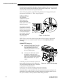
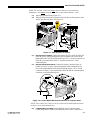
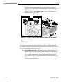
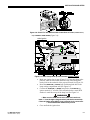
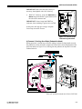
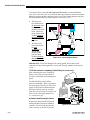
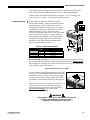
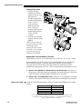
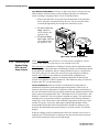
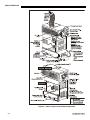
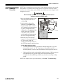
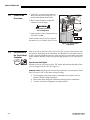
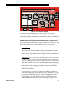
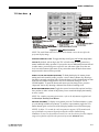
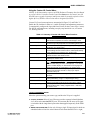
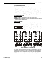
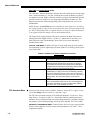
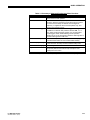
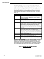
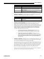
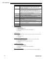
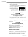
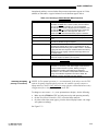
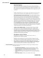
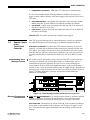
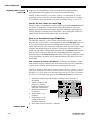
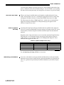
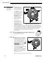
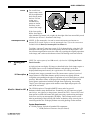
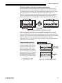
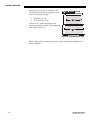
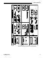
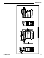
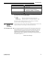
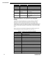
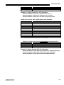
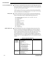
BASIC OPERATION CP2000 components are briefly described and listed in alphabetical order below: Air Filter Intake air flows through the filter before circulating in the front compartment to cool the main electronics. Replace the air filter whenever the lamp is replaced—or sooner in dusty/dirty environments. Check condition monthly. See 6.4, Replacing the Lamp & Filter for complete instructions. Breaker Panel Each circuit breaker on the pedestal serves two purposes: 1) it is a power switch for one or more components, and 2) it protects against over-current conditions. All breakers must be ON for normal CP2000 power-up and operation, enabling AC to reach the CP components. If faulty or excessive AC is detected, a breaker will “trip” to OFF in order to prevent damage to the relevant component. Try moving the breaker ON again—if the breaker continues to trip OFF, the AC problem must be resolved. Breakers are: MAIN AC (3-phase): Turns the CP lamp ballast, liquid cooling system, Ethernet hub and TPC on/off. The 3 switches move in tandem. PROJECTOR: Turns the CP projection head (electronics only—not the lamp) on/off. INTERNAL (single-phase): Turns on/off any extra equipment, such as an extractor fan mounted within the exhaust duct, that has been plugged into the CP’s internal convenience outlet (or terminal block in 400 VAC models). Functional only with 5-wire or 6-wire AC supplies. NOTE: Called “AUX” on CP2000-S models for connection of CineIPMs. NOTE: Breakers do not ignite the lamp. You must use the TPC Lamp Button. Casters The 4 large casters are typically used only when the CP is rolled into place for installation, or if the projector is moved from one location to another. When the projector leveling feet (recommended for all installations) are extended enough to raise the projector, the casters will spin freely and can be removed if desired. Coolant Level Gauge This gauge indicates the current level of coolant present for circulating to the main electronics in the front portion of the projection head. Keep the liquid level close to— but not above—the top notch. Refill if the level drops near to the bottom notch. Exhaust Duct Connect the projector’s 8” top exhaust hole to an outside-vented duct, with at least 10” of the last portion of the duct rigid at the projector. The duct will also need a heat extractor providing the 600 cf/m airflow required of all models. See Section 2, Installation & Setup. Extender Legs The rear feet of the projector are attached to extendable legs for more radical tilt (up to 12°) than possible with the feet only. For best optical performance, tilt the projector so that it is parallel to the screen—but always avoid radical tilt (such as LIT MAN USR CP2000 020-100032-04 Rev. 1 (03/14) 3-3