1
Options
Cryo Traps Option
_________________________________________________ Finnigan GasBench II
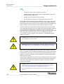
Notes for GasBench II Trapping System
Installation Note
GasBench II can either be equipped with
•
a single trap system or with
•
a dual trap system.
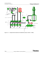
The single trap system serves as a cryogenic pre-concentration unit for flows
in the range of the GC column flow, that is 0.5-5 ml/min. Depending on the
GC performance needed, a fused silica trap (0.32 mm fused silica tubing from
valco port A to port B) for very sharp GC peaks or a nickel-filled stainless
steel trap (inner diameter: i.d. = 1 mm) resulting in broad GC peaks can be
used. In case of the stainless steel trap, the sample flow can also be increased
up to 15 ml/min.
Note. A longer fused silica capillary needs to be installed in the vent exit (Y)
of the valco valve to avoid freezing of ambient air into the trap.
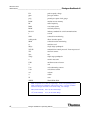
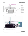
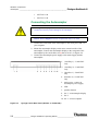
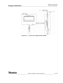
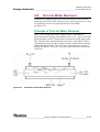
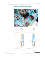
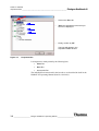
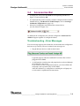
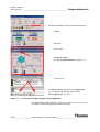
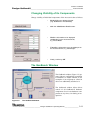
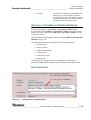
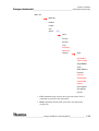
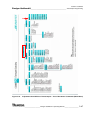
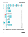
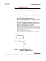
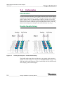
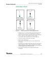
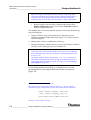
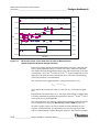
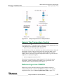
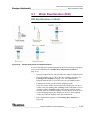
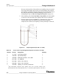
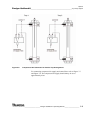
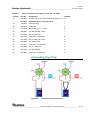
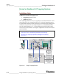
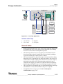
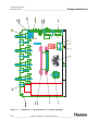
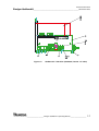
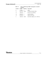
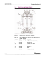
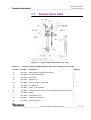
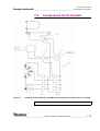
See Figure 6-9 (single trap application) and Figure 6-10 (dual trap
application).
Hein
Y Vent
to IRMS
GasBench
Pora PLOT Q
Sa in
Open
Split
B
Load
- H2O
Hein
X
A
GC
- H2O
Autosampler
A: Injector
Loop In
B: Injector
Loop Out
GBSingleTrap
Z
Trap 1
SS Nickel filled
Cryo- Concentration
X: Change He-in
and Sa-out at the Valco
Y: Vent capillary needs
to be prolonged
Z: Depending on the
Sa-flow Trap 2 may be
SS Nickel filled or
fused silica
Figure 6-9.
Single Trap Application
6-12 ___________________ Finnigan GasBench II Operating Manual ____________________
Thermo
ELECTRON CORPORATION