1
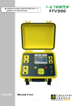
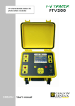
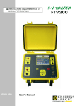
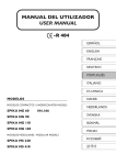
Testing instrument for photovoltaic installations
ENGLISH
User’s manual
GREEN TEST-FTV 100
English
FOREWORD
Thank you for purchasing this GREEN TEST FTV 100.
For best results from your instrument:
• read this operating manual carefully
• observe the safety precautions
Meanings of the symbols used on the instrument
Selective disposal for the recycling of electric
and electronic material required in the European
Union.
Under directive WEEE 2002/96/EC, this
equipment must not be treated as a household
waste.
CAUTION - DANGER! Refer to the operating
instructions. Failure to correctly observe or
perform instructions in this manual preceded by
this symbol may result in bodily injury or
damage to the device and to the installations.
Compliant with European Union directives.
Device entirely protected by double insulation or
reinforced insulation.
USB port
PRECAUTIONS FOR USE
The instructions that follow are mandatory for correct use of the instrument. Failure to comply with these
precautions may result in an electric shock, explosion, or fire.
♦
The user is invited to refer to these instructions whenever the
♦
Improper use of the instrument impairs its protection functions and may create a hazardous
situation.
♦
When removing and installing the battery, make sure that the test leads, sensors, and power
supply units are disconnected. The instrument must be disconnected and locked off.
♦
Responsibility for the safety of any installation built using this tool lies with the system
assembler.
♦
For your safety, use only the compatible accessories and cables supplied with the instrument,
in conformity with IEC standard 61010-031 (2002). When sensors or accessories having a
lower voltage rating and/or category than the device are used, the lower voltage rating and/or
category applies to the system so constituted.
symbol appears.
Page 2 sur 47
GREEN TEST-FTV 100
English
♦
Before each use, check that the cables, housings, and accessories are in perfect condition.
Any cable, sensor, or accessory of which the insulation is damaged (even partially) must be
repaired or scrapped.
♦
Comply with the environmental conditions.
♦
We recommend using the personal protection equipment appropriate to the environmental
conditions of use of the instrument.
♦
This tool can be used on class IV installations at voltages (AC or DC) not exceeding 600V
referred to earth (IEC 61010-1) or on category III installations, at voltages not exceeding
1000V. Never use the instrument on networks of which the voltage or category exceeds those
mentioned.
♦
Use the instrument only with the mains power supply unit or the battery pack supplied by the
manufacturer. These units include specific safety devices.
♦
Observe the limits of physical protection of the equipment and sensors. Keep your hands away
from unused terminals.
MEASUREMENT CATEGORIES
Definitions of the measurement categories according to EN-61010-1:
CAT I:
Measurement category I corresponds to measurements taken on circuits not directly connected to
the network.
CAT II:
Measurement category II corresponds to measurements taken on circuits directly connected to the
network.
Example: measurements on electrodomestic units, portable tools, and similar devices
CAT III:
Measurement category III corresponds to measurements on building installations.
Example: measurements on distribution panels and wiring.
CAT IV: Measurement category IV corresponds to measurements taken at the source of low-voltage
installations.
Example: meters and measurements on overvoltage protection devices.
REMARKS CONCERNING THIS MANUAL
♦
The information in this manual is subject to change without notice. The manufacturer cannot
be held liable for any errors it may contain.
♦
Great care has been taken in the preparation of this manual, but should you, even so, have
remarks to make, encounter difficulties in using our product, or have questions about it, please
get in touch either with your dealer or with us.
♦
Make sure that you fully understand the conditions of use of the product, such as its hardware
and software characteristics and its constraints of use. We cannot be held liable for damage
caused by improper use of the device.
♦
Reproduction of this manual or of any part of it without our prior written permission is
forbidden.\
♦
The names of products mentioned in this manual may be the trademarks, registered or not, of
their respective owners.
Page 3 sur 47
GREEN TEST-FTV 100
English
CONTENTS
FOREWORD................................................................................................................. 2
Meanings of the symbols used on the instrument ......................................................................................... 2
PRECAUTIONS FOR USE.............................................................................................. 2
MEASUREMENT CATEGORIES ...................................................................................... 3
REMARKS CONCERNING THIS MANUAL ...................................................................... 3
CONTENTS .................................................................................................................. 4
1. INTRODUCTION...................................................................................................... 6
2. CONTENT OF THE DELIVERY ................................................................................... 6
3. PRESENTATION ...................................................................................................... 7
4. SWITCHING ON/OFF .............................................................................................. 8
5. PREPARING THE SCREEN ........................................................................................ 9
6. POWER SUPPLY .................................................................................................... 12
6.1 BATTERY LIFE BETWEEN CHARGES........................................................................ 12
6.2 CHARGING THE BATTERY ..................................................................................... 12
6.3 POWER SUPPLY................................................................................................... 12
7. MENU TREE ........................................................................................................... 13
8. DESCRIPTION OF THE MENUS............................................................................... 16
8.1 USING THE ALPHANUMERIC KEYPAD ..................................................................... 16
8.2 SITE MENU......................................................................................................... 16
8.2.1 NEW SITE DATA ......................................................................................... 16
8.2.2
A LOOK AT THE THEORY .............................................................................. 16
8.2.3
SELECT A SITE ........................................................................................... 17
8.2.4
MODIFY A SITE........................................................................................... 17
8.3 MEASUREMENT MENU.......................................................................................... 17
8.3.1 MEASUREMENT ACQUISITION ...................................................................... 17
8.3.2
MEASUREMENT ACQUIRED........................................................................... 18
8.4 ADJUSTMENTS MENU........................................................................................... 19
8.5 CONFIGURATION ................................................................................................ 20
8.6 REMOTE MEASUREMENT ...................................................................................... 20
8.7 LOCATIONS OF THE MEASUREMENT POINTS ON THE PHOTOVOLTAIC PANELS............ 21
8.8 MEASUREMENT ACQUISITION............................................................................... 22
8.9 LOCATIONS OF THE MEASUREMENT POINTS ON A SINGLE-PHASE INVERTER ............. 23
8.10 MEASUREMENT ACQUISITION............................................................................. 24
8.11 CONNECTIONS OF THE MEASUREMENTS OF THE COMPLETE SITE WITH SINGLE-PHASE
OUTPUT................................................................................................................... 25
8.12 MEASUREMENT ACQUISITION............................................................................. 26
8.13 LOCATIONS OF THE MEASUREMENT POINTS ON A THREE-PHASE INVERTER............. 27
8.14 MEASUREMENT ACQUISITION............................................................................. 28
8.15 CONNECTIONS OF THE MEASUREMENTS OF THE COMPLETE SITE WITH THREE-PHASE
OUTPUT................................................................................................................... 29
8.16 MEASUREMENT ACQUISITION............................................................................. 30
Page 4 sur 47
GREEN TEST-FTV 100
English
8.17 MEASUREMENT OF THE COMPLETE SITE IN TWO SEPARATE STAGES ....................... 30
8.18 COMMUNICATION INTERFACE............................................................................. 31
8.18.1 RS232 INTERFACE - TECHNICAL CHARACTERISTICS.................................... 31
8.18.2
USB INTERFACE - TECHNICAL CHARACTERISTICS ....................................... 31
8.19 "GREEN REPORT" SOFTWARE.............................................................................. 31
8.19.1 GREEN REPORT SOFTWARE INSTALLATION PROCEDURE .............................. 32
8.19.2
8.19.2.1
8.19.2.2
8.19.2.3
8.19.2.4
8.19.2.5
8.19.2.6
8.19.3
FUNCTIONS OF THE GREEN REPORT SOFTWARE ......................................... 32
CONFIGURATION ..................................................................................................................... 32
CONNECTION OF THE INSTRUMENT TO THE PC:............................................................... 32
"REPORT".................................................................................................................................. 33
"REAL TIME".............................................................................................................................. 33
"DATA ACQUIRED" ................................................................................................................... 33
"INSTALLATIONS" .................................................................................................................... 33
EXAMPLES OF GRAPHS CREATED BY "GREEN REPORT" SOFTWARE ................ 34
9. REPORT ON STATUSES AND MEASUREMENTS ....................................................... 34
10. TECHNICAL CHARACTERISTICS OF THE INSTRUMENT ........................................ 36
11. CHARACTERISTICS OF THE REMOTED MODULE................................................... 37
11.1 PROCEDURE FOR CONNECTION AND CONFIGURATION OF THE REMOTED FTV 100
MODULE .................................................................................................................. 38
12. TECHNICAL CHARACTERISTICS OF THE "BLUETOOTH" COMMUNICATION KIT.... 39
13. TECHNICAL CHARACTERISTICS OF THE "CABLE" KIT ......................................... 40
13.1 PROCEDURE FOR CONNECTION AND CONFIGURATION OF THE "BLUETOOTH" OR
"RS232 CABLE" COMMUNICATION KIT ........................................................................ 40
14. PRODUCING A CABLE USING THE RS232 CONNECTORS PROVIDED WITH THE
OPTIONAL REMOTED FTV 100 MODULE .................................................................... 41
15. TECHNICAL CHARACTERISTICS OF THE PYRANOMETER...................................... 41
15.1 INTRODUCTION ................................................................................................ 41
15.2 OPERATING PRINCIPLE ...................................................................................... 41
15.3 INSTALLATION AND ASSEMBLY OF THE PYRANOMETER.......................................... 42
15.4 TECHNICAL CHARACTERISTICS........................................................................... 43
16. WARRANTY......................................................................................................... 43
17. MAINTENANCE.................................................................................................... 44
17.1 CLEANING ........................................................................................................ 44
17.2 METROLOGICAL CHECKS.................................................................................... 44
17.3 REPAIRS .......................................................................................................... 44
17.4 REPAIR OUTSIDE WARRANTY......................................... ERREUR ! SIGNET NON DEFINI.
18. TO ORDER........................................................................................................... 45
Page 5 sur 47
GREEN TEST-FTV 100
English
1. INTRODUCTION
The GREEN TEST FTV 100 is a measuring instrument designed and built to meet the needs of technicians
during the installation, testing, certification, and maintenance of photovoltaic systems.
Photovoltaic systems comprise two parts:
♦
A photovoltaic generator, comprising one or more series of photovoltaic panels that generate
a direct current.
♦
The inverter that converts the direct current generated by the panels into an alternating
current that is supplied to the network for use.
The GREEN TEST FTV 100 has three inputs for measurements of the voltage (VDC) and current (IDC)
delivered by the photovoltaic generator, making it possible to measure up to three series of solar panels at a
time. Depending on the needs of the installation, you may use one input, two, or all three.
The other side of the instrument has three inputs for measurements of AC voltages (VAC) and three for
measurements of alternating currents (IAC), making possible measurements on one, two, or three phases.
Make sure that the voltage and current connections are in phase, to avoid the acquisition of errored
measurements.
The measurements available on the GREEN TEST FTV 100:
♦
measurement of solar radiation by pyranometer (up to 2000W/m²);
♦
measurement of outdoor temperature using a Pt100 probe (up to 80°C);
♦
measurement of the temperature of the solar panels using a Pt100 probe (up to 120°C);
♦
calculations of the theoretical power available;
♦
measurement of the voltage (1000VDC), of the current (PAC10-FTV current clamps 200ADC,
PAC20-FTV current clamps 1400 ADC) and of the power delivered by the solar panels;
♦
measurement of the voltage (600VAC), of the current (MN-FTV current clamps 200AAC, C107FTV current clamps1000AAC, D43-FTV current clamps 3000AAC) and of the output power of the
inverter;
♦
calculation of the efficiency of the solar panels with display of the values and highlighting of the
test result;
♦
calculation of the DC/AC energy conversion (inverter) efficiency with display of the values and
highlighting of the test result;
♦
Memory used to store customer data and system measurements;
2. CONTENT OF THE DELIVERY
Basic equipment
Description
Pyranometer for solar radiation + connecting
cable
Pt100 probe for the ambient temperature
Pt100 probe for the temperature of the panels
Qty
1
1
1
Optional equipment
Description
D43-FTV ammeter clamps for measurement of
the alternating current (3000AAC)
C107-FTV ammeter clamps for measurement
of the alternating current (1000AAC)
PAC10-FTV ammeter clamps for
measurement of the direct current (200ADC)
Page 6 sur 47
GREEN TEST-FTV 100
English
MN-FTV ammeter clamps for measurement
of the alternating current (200AAC)
PAC10-FTV ammeter clamps for
measurement of the direct current (200ADC)
Set of 3m leads (red/black)
3
Pairs of test probes (red/black)
4
4.5Ah Li-Ion battery
Power supply unit
USB cable
Transport accessories
Certificate of validation of the instrument
CD-ROM containing:
Operating manual of the Green Test FTV 100
Green Report V2.5 + instructions
UpLoader 2.1 + instructions
USB serial driver + instructions
1
1
1
1
1
1
PAC20-FTV ammeter clamps for
measurement of the direct current (1400ADC)
FTV 100 remoted module + 2 male/male
RS232 connectors
Bluetooth communication kit
(transmitter/receiver)
15m serial cable with male/male RS232
connector
RS232/USB adapter
Alligator clips
No. 22 carrying bag
1
4
3. PRESENTATION
1
7
8
2
9
3
22
4
10
20
5
11
21
6
12
19
18
13
15
14
16
17
Page 7 sur 47
GREEN TEST-FTV 100
1.
2.
3.
4.
5.
6.
7.
8.
9.
10.
11.
12.
13.
14.
15.
16.
17.
18.
19.
20.
21.
English
input 1: ammeter clamp AAC
input 2: ammeter clamp AAC
input 3: ammeter clamp AAC
input 2: ammeter clamp ADC
input 2: ammeter clamp ADC
input 3: ammeter clamp ADC
input 1: voltage VAC
input 2: voltage VAC
input 3: voltage VAC
input 1: voltage VDC
input 2: voltage VDC
input 3: voltage VDC
ambient temperature probe input
pyranometer input
solar panel temperature probe input
USB serial port (to PC)
RS232 serial port –to remoted unit)
multi-function alphanumeric keypad having the following keys:
"up" navigation key
ENTER
selection validation key
"down" navigation key
▲
▼
On/Off button
ESC
menu exit key
DEL
entry deletion key
input of external power supply (15V DC, 2A maximum consumed)
PWR ON/CHARGE FULL (only when an external power supply is connected); lights during
recharging of the internal batteries or when they have reached full charge.
BAT Ch (only when an external power supply is connected); lights during the charging of the
batteries.
4. SWITCHING ON/OFF
Pressing the
button for 1 second switches the instrument on.
Pressing the
button for 3 seconds when the instrument is on switches it off.
REMARK: Pressing for more than one second when switching on may resulting in faulty lighting of the
screen.
If this happens, hold the
button down for more than 3 seconds, then switch the instrument back on.
The instrument can operate on battery power alone (without the external supply) if it is adequately charged,
or when connected to the power supply unit.
Page 8 sur 47
GREEN TEST-FTV 100
English
5. PREPARING THE SCREEN
The GREEN TEST FTV 100 has a 5.7" LCD screen that displays all measurements and the results of the
efficiency calculations in real time.
1
SYSTEM
4
5
6
1
2
POWER [kW]: ]: 7.50
MIN RAD [W/m2]: 600.00
ENVIRONMENT MEASUREMENT
Radiation W/m2:
0.00
environm temp. °C:
---.-panel temp.
°C:
---.-temp. coeff.:
-.-THEORATICAL
AVAIL POWER [kW]:
0.00
PANEL EFFICIENCY
--.-%
INVERTER EFFICIENCY
DC POWER [kW]:
0.00
8
AC MEASURE
V1: - ∗ V2: - ∗ V3: - ∗ -
ERROR
0.00A
0.00A
0.00A
I1:
I2:
I3:
AC POWER [kW]:
3.
4.
FUNCTION MENU
INSTALLATION
MEASURE
ADJUSTMENT
CONFIGURATION
REMOTE MEASURE
OFF
WARNING
0.00
12
1.
2.
11
--.-%
DC MEASUREMENT
ERROR
V1: - ∗ I1: - 37.9A
V2: - ∗ I2: - 38.1A
V3: - ∗ I3: - 38.9A
7
9
3
14
13
15
IMP: indicates the number of the photovoltaic installation selected
POWER [kW]: indicates the nominal power of the photovoltaic installation (value entered by the
user).
MIN RAD [W/m²]: indicates the minimum insolation required for the performance calculations
(see ADJUSTMENTS MENU). The default value is 600 W/m².
ENVIRONMENT MEASURES:
Radiation W/m²:
indicates the insolation measured by pyranometer (located on the
panels and having the same inclination) (see also the directions
for use of the pyranometer).
temp. environm °C:
indicates the value of environme nt temperature measured by a
Pt100 probe.
temp. panels °C:
indicates the temperature of the solar panels measured by a
Pt100 probe.
temp. coeff.:
indicates the panel performance correction parameter.
This value changes when the temperature is above the data
entered (NOCT).
It is a constant 0.85 when the temperature is between 0°C and
the NOCT (normal operating cell temperature).
Page 9 sur 47
GREEN TEST-FTV 100
English
When it exceeds the NOCT, the coefficient falls below 0.85 and
the panel loses efficiency (see page 34, §15.2).
The variation of the temperature coefficient also depends on the
values entered for Gamma and for NOCT.
REMARK: For all of the atmospheric measurements above, when the screen displays “---,--“ with the text
LOST (in red) at bottom right, communication has been broken off between the GREEN TEST instrument
and the remoted module. This interruption may be because the batteries of the remoted module are
discharged or because the signal has been lost (no Bluetooth link).
5.
THEORETICAL AVAILABLE POWER [kW]: theoretical power for an insolation of 1000 W/m²
(value entered by the user, see SITE MENU – NEW SITE DATA).
6.
DC MEASUREMENTS:
Display blank
V1: DC voltage or “- * -“
I1: direct current or -37.9A (-279.3A in 1.4kA version)
V2: DC voltage or “- * -“
I2: direct current or -38.1A (-279.8A in 1.4kA version)
V3: DC voltage or “- * -“
I3: direct current or -38.9A (-276.2A in 1.4kA version)
- ∗ -: alert for each individual input (V1, V2, or V3):
No connection to the PV system
Voltage < 10VDC
DC polarity reversed
AC voltage on DC inputs (connection error)
The “- * -” symbol also flashes
7.
8.
WARNING is displayed at bottom right of the screen
DC POWER [kW]: indicates the measured direct current power from the solar generator.
ALTERNATING CURRENT MEASUREMENTS:
Display blank
V1: AC voltage or “- * -“
I1: alternating current (2.0A for the 3kA version)
V2: AC voltage or “- * -“
I2: alternating current (1.0A for the 3kA version)
V3: AC voltage or “- * -“
I3: alternating current (1.1A for the 3kA version)
- ∗ -: alert for each individual input (V1, V2, or V3):
No connection to the PV system
Voltage < 25VAC
The “- * -” symbol also flashes
WARNING is displayed at bottom right of the screen
REMARK: when connecting to the PV system, check that the phases correspond (V1-I1, V2-I2, etc.)
9.
10.
AC POWER [kW]: indicates the measured AC output power of the inverter.
EFFICIENCY OF PANELS: indicates the efficiency of the photovoltaic generator as a
percentage (%), along with all of the test results.
REMARK: if Italian is the language selected for this device, under the provisions of standards applicable in
Italy (DM19/02/2007, IEC guide 82-25), the results of the "Good/Bad" tests appear alongside the %
efficiencies.
Page 10 sur 47
GREEN TEST-FTV 100
In this case:
11.
Measurements
in percentage
(%)
English
TEST
RESULTS
From ≥85% to
99.9%
From 0% to
<85%
REJECTED
>99.9
“-----“
OK
REMARK
Value in percentage and "OK" displayed in steady green
Value in percentage and "REJECTED" displayed in steady red
Flashing red dashes: anomaly, check the measurement
parameters (power, current, voltage, insolation) and the
connections of the photovoltaic system
INVERTER EFFICIENCY indicates the efficiency of the DC/AC conversion as a percentage and
displays all checks.
REMARK: if Italian is the language selected for this device, under the provisions of standards applicable in
Italy (DM19/02/2007, IEC guide 82-25), the results of the "Good/Bad" tests appear alongside the %
efficiencies.
In this case:
Measurements in TEST RESULTS
percentage (%)
12.
13.
14.
15.
From ≥90% to
99.9%
From 0% to <90%
OK
REJECTED
>99.9
“----- “
REMARK
Value in percentage and "OK" displayed in steady green
Value in percentage and "REJECTED" displayed in steady red
Flashing red dashes: anomaly, check the measurement parameters
(power, current, voltage, insolation) and the connections of the
photovoltaic system
ERROR: indicates an alert in the following cases:
- Wrong connections between the photovoltaic installation and the FTV 100, in the
matching of the AC measurement phases (for example V1-I2, current clamps connected
backwards) resulting in a negative AC power reading;
- Wrong connections between the photovoltaic installation and the FTV 100, in the DC
measurements part (current clamps connected backwards) resulting in a negative DC
power reading.
DC CURRENT (current clamps not connected): Because of the great sensitivity of the inputs
and their high impedances, the display unit indicates non-zero values. When a clamp is
connected, this value can briefly reach (for the 200A clamp) I1 = -37.9A, I2 = -38.1A, I3 = -38.9A
or (for the 1.4kA clamp) I1 = -279.3A, I2 = -279.8A, I3 = -276.2A) before falling back to zero.
If low values remain displayed for a non-zero direct current when clamps are connected to the
instrument, adjust the potentiometer to eliminate the residual magnetization of the ammeter
causing the "ZERO" reading (see the instructions in the PAC current clamps manual).
AC CURRENT (current clamps not connected): When the instrument is switched on, the
alternating current displayed is zero.
OFF–ON–LOST INDICATIONS (REMOTE MEASUREMENT MENU) set to point 15, these texts
may indicate:
OFF (red): If the remote module is used, it is possible to choose
"with" or "without" the panel temperature probe (see ENVIRONMENT MEASUREMENT
sub-menu);
ON (red): The instrument is connected to the remoted module in the two cases anticipated
(see ENVIRONMENT MEASUREMENT sub-menu);
LOST (red): interruption of communication between the GREEN TEST instrument and the
remoted module, because the batteries of the remoted module are discharged or the
signal has been lost (no Bluetooth transmission).
The response time of the instrument for the display of "Lost" is approximately 20
seconds.
Communication is restored automatically only if the instrument and the remoted
module are off (ON is displayed on the screen instead of LOST).
Page 11 sur 47
GREEN TEST-FTV 100
English
6. POWER SUPPLY
6.1 BATTERY LIFE BETWEEN CHARGES
The battery icon at bottom right on the screen indicates the charge level (proportional to the number of bars
of the icon that are visible).
Battery full. Life: approximately 8 hours
Battery half-charged. Life: approximately 30 minutes
Battery discharged (symbol flashes). Life: approximately 10 minutes
6.2 CHARGING THE BATTERY
The battery is charged with the instrument off, using the mains adapter provided, connected to the
corresponding jack. Even with the instrument connected to mains, you cannot charge the battery if the
instrument is on.
We recommend using only the mains adapter supplied with the instrument. It is specially designed for it and
ensures electric safety.
If the battery is fully discharged, the charging time is approximately 5 hours.
6.3 POWER SUPPLY
The power supply unit is compatible with voltages between 90V and 260V, at 50Hz. Its internal fuses are not
accessible.
REMARK: If the fuses blow, do not attempt to replace them, but send the power supply unit to Customer
Service for inspection.
Page 12 sur 47
GREEN TEST-FTV 100
English
7. MENU TREE
When the instrument is powered up, the "FUNCTIONS MENU" is displayed in the bottom right part of the
screen.
Page 13 sur 47
GREEN TEST-FTV 100
English
Page 14 sur 47
GREEN TEST-FTV 100
English
Page 15 sur 47
GREEN TEST-FTV 100
English
8. DESCRIPTION OF THE MENUS
When the instrument is switched on and the main screen is displayed, the bottom right box contains the
"FUNCTIONS MENU" with the main options. Each menu option selected gives access to one of the specific
functions described below.
Emissivity:
8.1 USING THE ALPHANUMERIC KEYPAD
Proceed as follows to select the options of the "FUNCTIONS MENU":
♦
Place the yellow cursor on the desired option using the • or •arrow key;
♦
Press the ENTER button to confirm each selection;
♦
Then enter the data using the alphanumeric keys, bearing in mind that by continuing to press
the same button you select the corresponding letters and figures;
♦
Press ENTER again to validate your entry.
8.2 SITE MENU
8.2.1 NEW SITE DATA
This function is used to adjust the parameters of the installation being checked, in addition to the register of
data concerning the sites, to print the certification document.
You can configure up to 20 sites in the memory of the instrument, each of which can acquire a maximum of
12 measurement reports (certifications).
REMARK: since the data concerning the POWER of the site, the SENSITIVITY of the pyranometer, and the
NOCT and GAMMA parameters are used for the efficiency calculations, make sure to enter the correct
values to avoid vitiating the calculations.
♦
Power of the site [kW]: indicates the theoretical power of the site;
♦
NOCT [°C]: nominal operating temperature of the cel l (data provided by the manufacturer of
the panels);
♦
GAMMA g [%/°C]: power vs. temperature coefficient o f the PV module (value entered between
0.01 and 0.99) (data provided by the manufacturer of the panels)
REMARK: enter the unsigned numerical value “+” or “-”;
♦
Name: indicates the name of the site;
♦
Address (street and number), postal code and Town: indicate the address of the site;
♦
Code: indicates the customer's tax file number;
♦
Select CONFIRMATION and wait for the data entered to be recorded.
REMARK: the data entered are recorded only if the power of the site, NOCT, and GAMMA have been
entered correctly.
8.2.2 A LOOK AT THE THEORY
One characteristic of the photovoltaic panels used, the parameter γ (gamma), is generally indicated by the
manufacturer of the panels. For modules made of crystalline silicon, it is generally 0.4-0.5%°C (to en ter the
value of g, refer to the description of the NEW SITE DATA MENU).
The NOCT parameter is characteristic of the photovoltaic panels used. It too is indicated by the
manufacturer of the panels. For modules made of crystalline silicon, it is generally between 40°C and 50°C.
Temperatures Tamb and Tcel are used in the calculations by the GREEN TEST FTV 100 and are measured
by a Pt100 temperature probe.
Page 16 sur 47
GREEN TEST-FTV 100
English
♦
Tcel, which is the cell temperature of a PV module, can be measured using a thermoresistive
sensor directly connected to the instrument or using the remoted FTV 100 module.
♦
Tamb is the ambient temperature, which can be measured using a sensor connected directly
to the instrument or using a remoted FTV 100 module (the probe is generally placed in the
shade).
In the measurement of PDC, if an operating temperature ≥40°C is measured on the backs of the modules, a
temperature correction of the site itself is allowed.
In this case, the relation Pcc > 0.85 x Pnom x I/Istc becomes:
PDC > (1 – Ptpv – 0.08) x Pnom x I/Istc
where Ptpv corresponds to the thermal losses of the photovoltaic generator.
Several practices exist. It is possible to select two types of mathematical relation to calculate the correction
factor.
The temperature of the photovoltaic cells being known, this parameter is calculated using the relation:
Ptpv = (Tcel – 25) x γ
Or, from the ambient temperature, by:
Ptpv = [Tamb - 25 + (NOCT – 20) x I/0,8] x γ
8.2.3 SELECT A SITE
This function is used to select the data of a photovoltaic site stored in memory. This configuration is used to
perform the measurements and as reference for a possible printed report.
This menu includes the following commands:
♦ NEXT SYSTEM
Press ENTER to go to the next recorded site
♦
PREVIOUS SYSTEM
Press ENTER to go to the previous recorded site
♦ ERASE SITE
Press ENTER to erase the selected site from memory
♦ ERASE ALL SITES
Press ENTER to erase all sites stored in memory
8.2.4 MODIFY A SITE
This function lets you modify the data of a site entered previously.
To make modifications, place the cursor on the line concerned and press ENTER, enter the new value, and
press ENTER again to confirm the modification.
Press ESC to confirm the modifications and update the data in memory.
8.3 MEASUREMENT MENU
8.3.1 MEASUREMENT ACQUISITION
Each of the 20 sites can acquire up to 12 measurement reports (certifications).
Press ENTER to select the measurements to be acquired.
♦
ENVIRONMENT AND DC
Press ENTER to select the ENVIRONMENT and DC measurements of the photovoltaic generator (a red
asterisk “*” appears on the element selected).
To confirm the storage of the selected measurements, place the cursor on CONFIRM MEASUREMENT and
press ENTER.
Page 17 sur 47
GREEN TEST-FTV 100
♦
English
INVERTER
Press ENTER to select the INVERTER measurements (DC and AC side) (a red asterisk “*” appears on the
element selected).
To confirm the storage of the selected measurements, place the cursor on CONFIRM MEASUREMENT and
press ENTER.
♦
ALL MEASUREMENTS
Press ENTER to select the ENVIRONMENT AND DC and INVERTER measurements (DC and AC side) (a
red asterisk “*” appears on the element selected).
To confirm the storage of the measurements selected, place the cursor on CONFIRM MEASUREMENT and
press ENTER.
♦
CANCELLED
Press ENTER to cancel the selections made previously.
8.3.2 MEASUREMENT ACQUIRED
Press ENTER to display the option RECOVERY OF STORED MEASUREMENTS, that corresponds to the
data of the sites stored in memory.
♦
NEXT SITE
Press ENTER to display the data of the site after the one currently displayed.
♦
PREVIOUS SITE
Press ENTER to display the data of the site before the one currently displayed.
♦
MEASUREMENT OF THE SITE SELECTED
Press ENTER to display all measurements of the selected system, with the test results (OK or REJECTED):
This menu includes the following commands:
♦ NEXT MEASUREMENT
Press ENTER to display the measurements of the site after the one currently displayed.
♦
PREVIOUS MEASUREMENT
Press ENTER to display the measurements of the site before the one currently displayed.
♦
ERASE THE SELECTED MEASUREMENTS
Press ENTER to erase the measurements of the selected site.
♦ ERASE ALL MEASUREMENTS
Press ENTER to erase the measurements of all sites stored in memory.
(*) for the efficiency calculation, a minimum insolation of 600W/m² or more on the plane of the modules
(gamma) is recommended. A radiation threshold can be assigned in the Adjustments menu.
Page 18 sur 47
GREEN TEST-FTV 100
English
8.4 ADJUSTMENTS MENU
Press ENTER to display the ADJUSTMENTS menu, which includes the following elements:
♦
PYRANOMETER
Press ENTER to select the SENSITIVITY OF THE PYRANOMETER (value expressed in [mV/(kW/m2)] and
displayed on the panel of the pyranometer) if it differs from the assigned value (see: standard sensitivity
value) or in the event of replacement.
Press ENTER to enter the sensitivity value.
Press ENTER again to validate the value entered.
♦
LOGO (NAME OF THE COMPANY THAT CERTIFIED THE SITE)
Press ENTER to select INSERTION OF THE LOGO.
Press ENTER to enter the abbreviated name of the installer company that makes the measurement or to
replace the name already entered.
Press ENTER again to validate the name entered.
♦
DATE/TIME
Press ENTER to select DATE/TIME.
Place the cursor on each field; press ENTER to enter a value (numerical only).
Press ENTER again to confirm the value entered.
Place the cursor on CONFIRMATION and press ENTER to record the data in memory.
REMARK: the data will appear in the certification documents.
♦
POWER CALCULATION
Press ENTER to select POWER CALCULATION.
This function is used to calculate the power with allowance for the Ptpv losses due to the reduction of
performance of the photovoltaic generator as a function of AMBIENT TEMPERATURE (Tamb) or of PANEL
TEMPERATURE (Tcel),
Place the cursor on the desired option and press ENTER to select it (a red asterisk "*" appears on the option
chosen).
♦
LANGUAGE
Press ENTER to select LANGUAGE.
Place the cursor on the desired option and press ENTER to select it (a red asterisk "*" appears on the option
chosen).
♦
DC MEASUREMENT
Press ENTER to select DC MEASUREMENT.
Place the cursor on the desired option and press ENTER to select a type of site on the DC side (a red
asterisk "*" appears on the option chosen).
Example: 1 = site with one chain, 1+2 = system with two chains, 1+2+3 = system with three chains.
♦
AC MEASUREMENT
Press ENTER to select AC MEASUREMENT.
Place the cursor on the desired option and press ENTER to select a type of site on the AC side (a red
asterisk "*" appears on the option chosen).
Example: 1 = site with one chain, 1+2 = system with two chains, 1+2+3 = system with three chains.
♦
MINIMUM INSOLATION
Press ENTER to select MINIMUM INSOLATION (W/m2).
Press ENTER to enter the minimum insolation used for the efficiency calculation.
Press ENTER again to validate the value entered.
Page 19 sur 47
GREEN TEST-FTV 100
♦
English
CURRENT CLAMPS
Press ENTER to select the "CURRENT CLAMPS" MENU.
Move the cursor to the desired IDC clamp model and press ENTER to validate your choice (a red asterisk "*"
appears on the option chosen).
Move the cursor to the desired IAC clamp model and press ENTER to validate your choice.
(a red asterisk "*" appears on the option chosen).
8.5 CONFIGURATION
Press ENTER to display the data of the instrument for updates and periodic checks:
♦
Serial number;
♦
Microprogram version installed;
♦
Version of video board.
8.6 REMOTE MEASUREMENT
Press ENTER to select REMOTE MEASUREMENT.
Place the cursor on the desired option and press ENTER to select the type of measurement.
♦
LOCAL
Press ENTER to select use of the local atmospheric input values present in the instrument, without the help
of the remoted FTV 100 module
(a red asterisk "*" appears on the option chosen).
A test of communication with the remoted module is performed. An indication, OK or REJECTED, appears at
the end of not more than 30 seconds (...Loading, flashing).
On the main screen, the REMOTE MEASUREMENT indication changes to ON.
The following functions can be activated only with the remoted FTV 100 module on and connected by
the optional communication kit (cable or Bluetooth).
♦
REMOTE WITHOUT T pan
Press ENTER to select use of the local atmospheric input values present on the remoted FTV 100 module,
without the AMBIENT TEMPERATURE value
(a red asterisk "*" appears on the option chosen).
The texts OK or REJECTED that appear at the end of 30 seconds (...LOADING, flashing) indicate the result
of the link with the data of the remoted FTV 100 module, and are confirmed on the main screen, to the right
of REMOTE MEASUREMENT, by ON or REJECTED.
♦ REMOTE WITH T pan
Press ENTER to select the use of the local atmospheric input values present on the remoted FTV 100
module, with the AMBIENT TEMPERATURE value
(a red asterisk "*" appears on the option chosen).
The texts OK or REJECTED that appear at the end of 30 seconds (...LOADING, flashing) indicate the result
of the link with the data of the remoted FTV 100 module, and are confirmed on the main screen, to the right
of REMOTE MEASUREMENT, by ON or REJECTED.
Page 20 sur 47
GREEN TEST-FTV 100
English
8.7 LOCATIONS OF THE MEASUREMENT POINTS ON THE
PHOTOVOLTAIC PANELS
1.
2.
3.
4.
5.
6.
7.
8.
Pyranometer
Panel temperature probe
Ambient temperature probe
Photovoltaic panel
DC current clamp
Inverter
Electric meter
Electric line
Figure 1: Locations of the measurement points on the photovoltaic panels
Page 21 sur 47
GREEN TEST-FTV 100
English
See Figure 1: Locations of the measurement points on the photovoltaic panels.
To make the measurements and determine the efficiency of the photovoltaic generator, proceed as follows:
1.
Connect the VDC MEASURE LINE1 voltage inputs to the DC voltage output of the photovoltaic
panel using the cables provided, respecting the polarity;
2.
Connect the DC current clamp, IDC MEASURE PROBE1, to the positive or negative cable of the
DC output of the photovoltaic panel. Note that the clamp is sensitive to the direction of the
current measured;
3.
Activate the clamp;
4.
Connect the pyranometer to the PYRANOMETER input. The pyranometer measures the
insolation;
5.
Connect the ambient temperature probe to the AMBIENT TEMPERATURE input. Place the
probe near the photovoltaic panel;
6.
Connect the contact probe to the PANEL TEMPERATURE input. Place the probe in thermal
contact with the photovoltaic panel.
8.8 MEASUREMENT ACQUISITION
Refer to the MEASUREMENT MENU: MEASUREMENT ACQUISITION
Page 22 sur 47
GREEN TEST-FTV 100
English
8.9 LOCATIONS OF THE MEASUREMENT POINTS ON A SINGLE-PHASE
INVERTER
1.
2.
3.
4.
5.
6.
Photovoltaic panel
DC current clamp
Inverter
AC current clamp
Electric meter
Electric line
Figure 2: Locations of the measurement points on a single-phase inverter
Page 23 sur 47
GREEN TEST-FTV 100
English
See Figure 2: Locations of the measurement points on a single-phase inverter.
To measure the efficiency of a single-phase inverter, proceed as follows:
1.
Connect the VDC MEASURE LINE1 voltage inputs to the DC voltage output of the photovoltaic
panel using the cables provided, respecting the polarity;
2.
Connect the DC current clamp to the IDC MEASURE PROBE1 input and to the positive or
negative cable of the DC output of the photovoltaic panel. Note that the clamp is sensitive to the
direction of the current measured;
3.
Connect the VAC MEASURE LINE1 voltage inputs to the AC voltage output of the inverter using
the cables provided;
4.
Connect the AC current clamp to the IAC MEASURE PROBE1 input and to the alternating
current output cable of the inverter.
8.10 MEASUREMENT ACQUISITION
Refer to the MEASUREMENT MENU: MEASUREMENT ACQUISITION
Page 24 sur 47
GREEN TEST-FTV 100
English
8.11 CONNECTIONS OF THE MEASUREMENTS OF THE COMPLETE
SITE WITH SINGLE-PHASE OUTPUT
2.
3.
4.
5.
6.
7.
8.
9.
Pyranometer
Panel temperature probe
Ambient temperature probe
Photovoltaic panel
DC current clamp
Inverter
AC current clamp
Electric meter
Electric line
Figure 3: Connections of the measurements of the complete site with single-phase output
Page 25 sur 47
GREEN TEST-FTV 100
English
See Figure 3: Connections of the measurements of the complete site with single-phase output
The measurements described in the previous chapters can be made simultaneously.
1.
2.
3.
4.
5.
6.
7.
8.
Connect the VDC MEASURE LINE1 voltage inputs to the DC voltage output of the photovoltaic
panel using the cables provided, respecting the polarity;
Connect the DC current clamp to the IDC MEASURE PROBE1 input and to the positive or
negative cable of the DC output of the photovoltaic panel. Note that the clamp is sensitive to the
direction of the current measured;
Activate the DC clamp;
Connect the pyranometer to the PYRANOMETER input. The pyranometer measures the
insolation;
Connect the ambient temperature probe to the AMBIENT TEMPERATURE input. Place the
probe near the photovoltaic panel;
Connect the contact probe to the PANEL TEMPERATURE input. Place the probe in thermal
contact with the photovoltaic panel;
Connect the VAC MEASURE LINE1 voltage inputs to the AC voltage output of the inverter using
the cables provided;
Connect the AC current clamp to the IAC MEASURE PROBE1 input and to the alternating
current output cable of the inverter.
8.12 MEASUREMENT ACQUISITION
Refer to the MEASUREMENT MENU: MEASUREMENT ACQUISITION
Page 26 sur 47
GREEN TEST-FTV 100
English
8.13 LOCATIONS OF THE MEASUREMENT POINTS ON A THREE-PHASE
INVERTER
1.
2.
3.
4.
5.
6.
Photovoltaic panel
DC current clamp
Inverter
AC current clamp
Electric meter
Electric line
Figure 4: Locations of the measurement points on a three-phase inverter
Page 27 sur 47
GREEN TEST-FTV 100
English
See Figure 4: Locations of the measurement points on a three-phase inverter.
1.
2.
3.
4.
5.
Connect the VDC MEASURE LINE1 voltage inputs to the DC voltage output of the photovoltaic
panel using the cables provided, respecting the polarity;
Connect the DC current clamp to the IDC MEASURE PROBE1 input and to the positive or
negative cable of the DC output of the photovoltaic panel. Note that the clamp is sensitive to the
direction of the current measured;
Activate the DC clamp;
Connect the VAC MEASURE LINE1- LINE2- LINE3 voltage inputs to the AC voltage output of
the inverter using the cables provided;
Connect the AC current clamp to the IAC MEASURE PROBE1- PROBE1- PROBE1 input and to
the alternating current output cable of the inverter.
N.B.: AC side: check that the phases exactly match in the connection between the inputs of the voltmeter
and of the ammeter:
VAC MEASURE LINE1 → IAC MEASURE PROBE1 phase L1,
VAC MEASURE LINE2 → IAC MEASURE PROBE2 phase L2,
VAC MEASURE LINE3 → IAC MEASURE PROBE3 phase L3,
8.14 MEASUREMENT ACQUISITION
Refer to the MEASUREMENT MENU: MEASUREMENT ACQUISITION
Page 28 sur 47
GREEN TEST-FTV 100
English
8.15 CONNECTIONS OF THE MEASUREMENTS OF THE COMPLETE
SITE WITH THREE-PHASE OUTPUT
1.
2.
3.
4.
5.
6.
7.
8.
9.
Pyranometer
Panel temperature probe
Ambient temperature probe
Photovoltaic panel
DC current clamp
Inverter
DC current clamp
Electric meter
Electric line
Figure 5: Connections of the measurements of the complete system with three-phase output
Page 29 sur 47
GREEN TEST-FTV 100
English
See Figure 5: Connections of the measurements of the complete system with three-phase output.
1.
2.
3.
4.
5.
6.
7.
8.
Connect the VDC MEASURE LINE1 voltage inputs to the DC output voltage of the photovoltaic
panel using the cables provided, respecting the polarity;
Connect the DC current clamp to the IDC MEASURE PROBE1 input and to the positive or
negative cable of the DC output of the photovoltaic panel. Note that the clamp is sensitive to the
direction of the current measured;
Activate the DC clamp;
Connect the pyranometer to the PYRANOMETER input. The pyranometer measures the
insolation;
Connect the ambient temperature probe to the AMBIENT TEMPERATURE input. Place the
probe near the photovoltaic panel;
Connect the probe to the PANEL TEMPERATURE. Place the probe in thermal contact with the
photovoltaic panel;
Connect the VAC MEASURE LINE1-LINE2-LINE3 voltage inputs to the AC voltage output of the
inverter using the cables provided;
Connect the AC current clamp to the IAC MEASURE PROBE1- PROBE1- PROBE1 input and to
the alternating current output cable of the inverter.
N.B.: AC side: check that the phases exactly match in the connections between the inputs of the voltmeter
and of the ammeter:
VAC MEASURE LINE1 → IAC MEASURE PROBE1 phase L1,
VAC MEASURE LINE2 → IAC MEASURE PROBE2 phase L2,
VAC MEASURE LINE3 → IAC MEASURE PROBE3 phase L3,
8.16 MEASUREMENT ACQUISITION
Refer to the MEASUREMENT MENU: MEASUREMENT ACQUISITION
8.17 MEASUREMENT OF THE COMPLETE SITE IN TWO SEPARATE
STAGES
Practice has taught us that the measurements of PCC, PCA, Gp, and Tamb used in the performance
calculations should be acquired simultaneously.
It is however possible to perform the checks in two stages (DC side and AC side), provided that the
insolation, temperature, and output power remain practically constant during the measurement.
HOW TO MAKE THE MEASUREMENT USING THE GREEN TEST FTV 100
DC SIDE (PHOTOVOLTAIC PANEL)
Stand facing the photovoltaic panels and connect the instrument as indicated by the "connection diagram
for the measurement of photovoltaic panels (§ 8.7)".
In the FUNCTIONS MENU - MEASUREMENT, select MEASUREMENT ACQUISITION and place the cursor
on ENVIRONMENT and DC.
Check the connections to the system and press ENTER to acquire the measurements (an “*” and the
flashing text, CURRENT ACQUISITION..., indicate that the operation is in progress).
Leave the GREEN TEST FTV 100 on, disconnect it from the DC part of the installation, and acquire
the measurements on the AC side downstream of the inverter.
Page 30 sur 47
GREEN TEST-FTV 100
English
AC SIDE (INVERTER)
Connect the instrument to the downstream side of the inverter and connect the instrument as indicated by
the "measurements connection diagram, single-phase inverter side (page 21)" or the "measurements
connection diagram, three-phase inverter side (page 25)".
In the FUNCTIONS MENU - MEASUREMENT, select MEASUREMENT ACQUISITION and place the cursor
on INVERTER.
Check the connections to the system and press ENTER to acquire the measurements (an “*” and the
flashing text CURRENT ACQUISITION... indicate that the operation is in progress).
To confirm the recording of the DC side and AC side measurements acquired, place the cursor on CONFIRM
MEASUREMENT and press ENTER (the text STORING MEASUREMENT... flashes to indicate that the
operation is in progress).
8.18 COMMUNICATION INTERFACE
The standard GREEN TEST FTV 100 has an RS232 interface (9-pin D-SUB), a USB interface, and enough
memory to store approximately 200 sets of measurement (one main measurement + secondary
measurements: voltage, current, power, atmospheric data, date, time, etc.).
The instrument includes a real-time clock for the date and the time.
The USB interface is used to process and transfer the stored data to a PC running GREEN REPORT
software.
8.18.1 RS232 INTERFACE - TECHNICAL CHARACTERISTICS
Data format: 1 start bit, 8 data bits, 1 stop bit, no parity, no protocol
Rate: 38,400 bauds
8.18.2 USB INTERFACE - TECHNICAL CHARACTERISTICS
Protocol v.2.0. If no communication is detected, please contact our Customer Service for the installation of
the driver.
The USB interface is also used to update the internal microprogram of the instrument (contact us for more
information).
8.19 "GREEN REPORT" SOFTWARE
The GREEN REPORT software on the CD-ROM provided is used for the following operations:
♦
remote management;
♦
management of the measurements stored on the instrument;
Page 31 sur 47
GREEN TEST-FTV 100
English
♦
printing of measurement reports and of the declaration of conformity issued at the end of the
tests of the site;
♦
real-time analysis of all measurements (manual or automatic) of the PV system;
♦
graphic display of all measurements of the PV system vs. time.
8.19.1 GREEN REPORT SOFTWARE INSTALLATION PROCEDURE
1.
2.
Insert the CD-ROM provided in the drive of the PC;
Click on the GREEN REPORT folder. When you have opened the folder, open the PDF
instruction file it contains and follow the instructions to ensure correct installation of the GREEN
REPORT software;
Once installed, the GREEN REPORT software is ready to be used.
3.
8.19.2 FUNCTIONS OF THE GREEN REPORT SOFTWARE
GREEN REPORT has several icons that represent its functions.
8.19.2.1 CONFIGURATION
By clicking on this icon, you can check the status of communication between the instrument (base unit) and
the remoted module.
Access to the CONFIGURATION function lets you perform the following operations:
♦
selection of the power calculation method (see the ADJUSTMENTS menu);
♦
selection of the number of DC inputs (current, voltage);
♦
selection of the number of AC inputs (current, voltage);
♦
selection of the minimum insolation for the efficiency calculation (very important if you want to
perform tests with an insolation of less than 600 W/m².
8.19.2.2 CONNECTION OF THE INSTRUMENT TO THE PC:
1.
To transfer the data acquired to the PC, connect the instrument to the PC using the USB cable:
♦
Click on the "CONFIGURATION" icon.
♦
Select the COM port of the device in the pull-down menu (if the COM port number does not
appear, look for it in the Windows Peripherals Manager).
♦
Click on “CONNECT THE BASE UNIT”.
♦
Wait for CONNECTION STATUS to be displayed:
- Green light (connection established);
- Red light (no connection).
2.
Acquisition of measurements in REAL TIME in LOCAL mode
♦
Connect the instrument to the PC using the USB cable.
♦
Click on the "CONFIGURATION" icon.
♦
Select the COM port of the device in the pull-down menu (if the COM port number does not
appear, look for it in the Windows Peripherals Manager).
♦
Click on "CONNECT THE BASE UNIT".
♦
Wait for CONNECTION STATUS to be displayed:
- Green light (connection established);
- Red light (no connection).
♦
Click on the REAL TIME icon (refer to the description of the REAL TIME menu).
Page 32 sur 47
GREEN TEST-FTV 100
3.
English
Remote acquisition of measurements in REAL TIME from the remoted module:
♦
Connect the instrument to the PC using the USB cable.
♦
Connect a Bluetooth adapter to the PC using the RS232 cable provided.
♦
Connect the other Bluetooth adapter to the remoted module using the RS232 cable provided.
♦
Click on the "CONFIGURATION" icon.
♦
Select the COM port of the device in the pull-down menu (if the COM port number does not
appear, look for it in the Windows Peripherals Manager).
♦
Click on "CONNECT THE BASE UNIT".
♦
Wait for CONNECTION STATUS to be displayed:
- Green light (connection established);
- Red light (no connection).
♦
Click on "CONNECTION OF REMOTE MODULE".
♦
Select REMOTE MEASUREMENT on the instrument and choose the type of measurement to
be made: REMOTE WITH T pan (when you use a PT100 probe on the solar panels) or
REMOTE WITHOUT T pan (if you do not use a PT100 probe for the solar panels).
♦
Press the ENTER key and wait for the OK message (if REJECTED is displayed, check the
connections and repeat the procedure).
♦
Press the ESC key to exit from the menu.
♦
Click on the REAL TIME icon (see the description of the menu of that name).
8.19.2.3 "REPORT"
This icon is used to select the SITE in the data base of the instrument or on the PC and the measurements
to be used to create the declaration and the system measurement sheet, along with the results of the
efficiency calculation.
The declaration is generated only if the result of the tests is OK. If not, only the measurement sheet is
generated.
8.19.2.4 "REAL TIME"
This icon is used to display in real time the measurements of the site in question (atmospheric
measurements, DC, AC, efficiencies, etc.), either manually or automatically at a predetermined date and
time. The data can be recorded in a TXT format and exported to spreadsheets.
8.19.2.5 "DATA ACQUIRED"
This icon is used to display the data of your sites, whether or not stored on the GREEN TEST FTV 100,
along with the data present in the PC's database, and create graphs of all quantities vs. time.
Analysis of these graphs is a very important aspect of the maintenance of your photovoltaic systems.
8.19.2.6 "INSTALLATIONS"
This icon is used to add a new site or to delete one from your PC's database.
Page 33 sur 47
GREEN TEST-FTV 100
English
8.19.3 EXAMPLES OF GRAPHS CREATED BY "GREEN REPORT" SOFTWARE
9. REPORT ON STATUSES AND MEASUREMENTS
The test is intended to prove and certify that the installation has been built in a professional manner and in
compliance with the technical requirements, in conformity with the need, and to make sure that it currently
functions properly.
The report groups all information concerning the place at which and the conditions under which the test was
performed.
Page 34 sur 47
GREEN TEST-FTV 100
English
Example of a Report of on-site measurement on the tests performed
Page 35 sur 47
GREEN TEST-FTV 100
English
10. TECHNICAL CHARACTERISTICS OF THE
INSTRUMENT
WARNING, DANGER!
Reference conditions: 23°C ±3°C; 45-75%
MONITOR
display area
resolution
contrast factor
luminosity
Surface treatment
visual angle
PYRANOMETER
AMBIENT
TEMPERATURE
TEMPERATURE OF
THE SOLAR
PANELS
DC VOLTMETER
CAT IV 600 V
DC AMMETER
Use a CAT III 600 V
class II clamp
AC VOLTMETER
CAT IV 600
AC AMMETER
Use a CAT III 600 V
class II clamp
AC/DC POWER
CALCULATION
FUNCTIONS
DATA RECORDER
COMMUNICATION
PORT
INTERNAL POWER
SUPPLY
MAINS POWER SUPPLY
High-luminosity digital colour LCD
5,7” (diagonal).
320 (W) x 240 (H) pixels.
300:1
2
400cd/m .
anti-glare and hard coating (>2H).
±55° (horizontal), ±60° (vertical).
probe measuring the insolation
Range 0 ÷ 2000W/m², accuracy ±2%
over any the whole measurement range according to the manufacturer's certification
Other characteristics according to the manufacturer's manual provided with the device
PT100 probe measuring the ambient temperature
Range -30 ÷ +80°C
Accuracy ± 1% ± 1°C from 0 to +80°C
PT100 probe measuring the temperature of the solar panels
Range -30 ÷ +120°C
Accuracy ± 1% ± 1°C from 0 to +90°C
CHECK THAT THE PANEL IS CLASS II
BEFORE PLACING THE TEMPERATURE PROBE
3 inputs for the simultaneous measurement of the output voltages of 3 solar panels
1000VDC full scale - accuracy ± 1% from 10 to 1000VDC
3 inputs for the simultaneous measurement of the output current of 3 solar panels
PAC10-FTV clamp
PAC20-FTV clamp
200ADC full scale - accuracy ± 1% from 2 to 200ADC
1400ADC full scale - accuracy ±1% from 5
(with the dedicated instrument only)
àto1400ADC
3 inputs for the simultaneous measurement of the voltages of three-phase lines with or
without neutral (use input 1 for single-phase lines)
600VAC 50Hz full scale - accuracy ±1% from 80 to 600VAC
3 inputs for the simultaneous measurement of the currents of three-phase lines (use
input 1 for single-phase lines)
MN-FTV mini-clamp
200AAC full scale - accuracy ±1% from 2 to 200AAC
1000AAC full scale - accuracy ±1% from 5 to
C107-FTV clamp
(with the dedicated instrument only)
1000AAC
3000AAC full scale - accuracy ±1% from 5 to
D43-FTV clamp
(with the dedicated instrument only)
3000AAC
accuracy < 2%
efficiency of the photovoltaic panels
with compensation for the temperature coefficient of the modules
inverter conversion efficiency
memory, including:
customer permanent data,
characteristics of the system, measurements and test results
Each of the 20 sites can acquire up to 12 measurement reports (certifications).
RS232 + USB for management of the boards and transfer of the data to a PC
Li-Ion battery pack, 4.5Ah, 8h life between charges
by external power supply unit 220VAC - 50Hz, 115VA, output 14.5-16VDC
Page 36 sur 47
GREEN TEST-FTV 100
English
OPERATING
TEMPERATURE
USE
MAXIMUM ALTITUDE
OF OPERATION
The device must not be used in the rain with the cover open
RELATIVE HUMIDITY
80% UP TO 40°C
(LINEAR DECREASE TO 50% AT 50°C).
STORAGE
TEMPERATURE
PROTECTION
DIMENSIONS
MASS
From 5°C to +40°C.
2000m.
From -10°C to +60°C.
protection index IP54 (with cover closed)
360 x 30 x 194mm
3KG (WITH BATTERY)
11. CHARACTERISTICS OF THE REMOTED MODULE
WARNING, DANGER!
The use of the remoted module allows the simultaneous measurement and display of the atmospheric
parameters on the GREEN TEST FTV 100 instrument, even when the panels are at a distance from the
inverter.
SERIAL COMMUNICATION
PORT
POWER SUPPLY
SWITCH (1)
LED INDICATOR (2)
CONNECTION
OPERATING
TEMPERATURE
USE
MAX. ALTITUDE OF
OPERATION
RELATIVE HUMIDITY
STORAGE
TEMPERATURE
DIMENSIONS
MASS
RS232 for real-time communication with the GREEN TEST FTV 100
instrument (using the optional "cable" or "Bluetooth" kit)
Internal: 4 standard 1.5V alkaline batteries, approximately 20h between
charges (without the Bluetooth kit) or 4 1.5V rechargeable batteries (not
provided)
On/Off button with mechanical selector
Lit steadily: remoted FTV 100 module with batteries adequately charged
Slow flashing: battery life of the remoted FTV 100 module
approximately 30 min. (battery charge level approximately
4.6V)
Rapid flashing: battery life of the remoted FTV 100 module
approximately 10 min. (battery charge level
approximately 3.6V). REMARK: we recommend replacing or recharging
the batteries immediately when the slow flashing stage is reached. The
remaining battery life depends on the type of battery used
(alkaline/rechargeable).
By 3 FRB connectors for the ambient temperature probe, the panel temperature
probe, and the pyranometer
from 5°C to +40°C.
In zones protected from water and rain
2000m.
80% UP TO 40°C (LINEAR DECREASE TO 50% AT 50°C).
from -10°C to +60°C.
85 x 60 x 150mm
500G (WITH BATTERY)
Page 37 sur 47
GREEN TEST-FTV 100
English
11.1 PROCEDURE FOR CONNECTION AND CONFIGURATION OF THE
REMOTED FTV 100 MODULE
1.
Connect the probes of the unit (temperature and insolation) to the corresponding inputs of the
remoted module (see photograph A)
Ambient temperature probe
Panel temperature probe
Photo A
Pyranometer
2.
Connect one of the Bluetooth units (a) or the RS232 connector (b) of the serial cable (if one is
provided); see photograph B
(a)
On/Off button (1)
RS232 connectors
(b)
3.
4.
5.
Photo B
Connect the GREEN TEST instrument to the other Bluetooth unit or to the RS232 connector of
the serial cable (if one is provided).
Power up the remoted module using the On/Off button (the LED indicators confirm the power up
and the presence of a power supply provided by the batteries).
Follow the instructions (see the REMOTE MEASUREMENT MENU) for activation of
communication with the instrument.
Page 38 sur 47
GREEN TEST-FTV 100
English
12. TECHNICAL CHARACTERISTICS OF THE
"BLUETOOTH" COMMUNICATION KIT
The Bluetooth kit is used to transmit the atmospheric parameters from the remoted module to the GREEN
TEST FTV 100 instrument when the panels are placed at a distance from the inverter.
I/O INTERFACE
POWER SUPPLY
POWER SUPPLY FOR
THE BLUETOOTH
SIGNAL
TRANSMISSION
FREQUENCY
SPECTRUM
RF OUTPUT POWER
DISTANCE
OPERATING
TEMPERATURE
USE
MAXIMUM ALTITUDE
OF OPERATION
RELATIVE HUMIDITY
STORAGE
TEMPERATURE
DIMENSIONS
MASS
Master unit and slave unit, already programmed, RS232 ports for the real-time
communication interface with the GREEN TEST FTV 100
by RS232 or mains adapter 230VAC (5…7,5V)
The minimum power supply provided by the remoted module for
communication between Bluetooth adapters is approximately 4.6V,
roughly equivalent to the low charge level of the battery (slow flashing of
the red indicator on the remoted module).
REMARK: in this case, we advise immediately replacing or recharging the
batteries.
Bluetooth v2.0 + EDR
2.4…2.4835GHz, ISM licence
FHSS
Class 1
100m - in free field
from 0°C to +60°C.
In zones protected from water and rain
2000m
90% up to 40°C
from -10°C to +70°C.
76 x 62 x 20mm
approximately 50g
Other characteristics according to the manufacturer's manual provided
The optional Bluetooth adapters are of the highest quality, with the best characteristics and
performance available on the market.
Even so, some situations may induce perturbations and interfere with communication.
In these situations, we suggest moving the Bluetooth adapter (connected to the instrument by a
cable of sufficient length fitted with the two male/male RS232 connectors supplied with the remoted
module).
Page 39 sur 47
GREEN TEST-FTV 100
English
13. TECHNICAL CHARACTERISTICS
OF THE "CABLE" KIT
The RS232 cable communication kit allows the transmission of the atmospheric parameters to the GREEN
TEST FTV 100 instrument by the remoted module, by means of a physical connection, when the panels are
placed at a distance from the inverter.
TYPE
LENGTH
CONNECTION
Minimum requirements: UTP Cat.5 cable, twisted pair
15m standard
(the male RS232 connectors should be soldered if the length is greater).
Male/male RS232 connectors
13.1 PROCEDURE FOR CONNECTION AND CONFIGURATION OF THE
"BLUETOOTH" OR "RS232 CABLE" COMMUNICATION KIT
1. Connect one of the two Bluetooth units or the RS232 connector (b) of the serial cable (if one is
provided) to the remoted module
2. Connect one of the two Bluetooth units or the RS232 connector (b) of the serial cable (if one is
provided) to the GREEN TEST unit.
3. Power up the remoted module using the On/Off button (the LED indicators confirm the power up and
the presence of a power supply provided by the batteries).
4. Follow the instructions (see the REMOTE MEASUREMENT MENU) for activation of communication
with the instrument.
5. Check that the blue indicator of the Bluetooth unit is lit, confirming that communication is active.
Instrument
Transmission
Remoted
module
Probes
Bluetooth
RS232 cable
Page 40 sur 47
GREEN TEST-FTV 100
English
14. PRODUCING A CABLE USING THE RS232
CONNECTORS PROVIDED WITH THE OPTIONAL
REMOTED FTV 100 MODULE
15. TECHNICAL CHARACTERISTICS OF THE
PYRANOMETER
WARNING, DANGER!
The user must take care not to connect the metallic parts of the pyranometer to a hazardous voltage.
15.1 INTRODUCTION
The LP PYRA 03 pyranometer measures the insolation on a plane surface (W/m²). The insolation measured
is the sum of the direct solar radiation and the diffuse radiation (total radiation).
15.2 OPERATING PRINCIPLE
The operation of the LP PYRA03 pyranometer is based on a thermopile sensor. The sensitive zone of the
thermopile is covered by a thin coat of black paint to make the response of the pyranometer to different
wavelengths unselective. The spectral band of the pyranometer is determined by the emission of a K5 type
glass dome.
The radiant energy is absorbed by the blackened surface of the thermopile, creating a temperature
difference between the centre of the thermopile (hot junction) and its body (cold junction). The temperature
difference between the hot and cold junctions is converted into a difference of potential by the Seebeck
effect.
Page 41 sur 47
GREEN TEST-FTV 100
English
The LP PYRA 03 has a dome having an outside diameter of 32mm, 4mm thick, in order to ensure adequate
thermal insulation of the thermopile against the effects of wind and to reduce its sensitivity to thermal
radiation. The dome also protects the thermopile from dust, which could otherwise modify the spectral
sensitivity by accumulating on the blackened part.
To prevent the formation of condensation on the inside of the dome in certain particular climatic conditions,
the pyranometer contains sachets of silica gel to absorb moisture.
15.3 INSTALLATION AND ASSEMBLY OF THE PYRANOMETER
♦
The pyranometer should be installed at a place where no buildings, trees, or other obstacles
mask the horizon. When this is impossible, we recommend choosing a location where
obstacles on the path of the rising and setting sun protrude less than 5° above the horizon.
N.B.: the presence of obstacles on the horizon significantly influences the direct insolation measurement.
♦
The pyranometer must be placed away from any obstacle that might reflect sunlight (or
shade).
Trous de fixation M 5
T rou de fixation
de l'anneau
de l'écran LPSP2
Trou s de fixation
traversan ts M 5
Example of positioning of the pyranometer
Page 42 sur 47
GREEN TEST-FTV 100
English
15.4 TECHNICAL CHARACTERISTICS
TYPICAL SENSITIVITY
IMPEDANCE
MEASUREMENT RANGE
MEASUREMENT ACCURACY*
RESPONSE TIME
FIELD OF VISION
SPECTRAL BAND
TRANSMISSION OF THE DOME
OPERATING TEMPERATURE
MASS
SAFETY
ELECTROSTATIC DISCHARGES
VOLTAGE VARIATION
EMC
* Environmental conditions 23°C ± 2% - RH 50% ±10%
2
10µV/(W/m )
33Ω ÷ 45Ω
2
0-2000W/m
1.5% typical
<30s
2 Π sr
305nm ÷ 2800nm (50%)
335nm ÷ 2200nm (95%)
-40°C ÷ 80°C
0,45kg
EN 61000-4-2, EN 61010-1, level 3
EN 61000-4-2, level 3
EN 61000-4-3
IEC 1000-4-3, EN 55020 class B
16. WARRANTY
The instruments we manufacture are guaranteed for twelve months against malfunctions due to defective
workmanship or materials.
To make a claim under the warranty, you must produce a copy of the invoice or of the receipt for the
purchase of the instrument.
The warranty does not apply in the following cases:
- Inappropriate use of the equipment or use with incompatible equipment;
- Modifications made to the equipment without the explicit permission of the manufacturer’s technical
staff;
- Work done on the device by a person not approved by the manufacturer;
- Adaptation to a particular application not anticipated in the definition of the equipment or not
indicated in the user’s manual;
- Damage caused by shocks, falls, or floods.
The batteries are not covered by the warranty.
Page 43 sur 47
GREEN TEST-FTV 100
English
17. MAINTENANCE
For maintenance, use only the specified spare parts. The manufacturer cannot be held liable for any
accident that occurs following a repair done by a party other than Chauvin-Arnoux customer service or an
approved repairer.
17.1 CLEANING
To ensure a highly accurate measurement, the outside of the dome must be kept clean at all times. The
more often the dome is cleaned, the more accurate the measurement. The cleaning can be done using
ordinary camera lens cleaning tissue and water or, if this is not sufficient, pure ethanol. After cleaning with
alcohol, the dome must be rinsed with plain water.
17.2 METROLOGICAL CHECKS
Like all measuring and testing devices, the instrument must be checked periodically.
Each pyranometer is individually calibrated in the plant and marked with its calibration factor. For best results
with the pyranometer, we recommend an annual check of the device. For checks and calibrations, get in
touch with our COFRAC-accredited metrology laboratories or with a MANUMESURE agency.
Information and contact data on request:
Tel.: 02 31 64 51 43
Fax: 02 31 64 51 09
17.3 REPAIRS
For repairs under the warranty, send your device to one of the CHAUVIN-ARNOUX-approved
MANUMESURE regional agencies.
Information and contact data on request:
Tel.: 02 31 64 51 43
Fax: 02 31 64 51 09
For repairs outside metropolitan France, whether or not under warranty, send the device to your distributor.
Page 44 sur 47
GREEN TEST-FTV 100
English
18. TO ORDER
GREEN TEST FTV 100...................................................................................................................P01160700
THE instrument is provided with:
♦
A carrying case containing the instrument;
♦
1 pyranometer for solar radiation + connecting cable;
♦
1 Pt100 probe for the ambient temperature;
♦
1 Pt100 probe for the temperature of the panels;
♦
3 MN13-FTV current clamps for measurement of the alternating current;
♦
1 PAC10-FTV current clamp for measurement of the direct current;
♦
4 sets of 3m leads (red/black);
♦
4 pairs of test probes (red/black);
♦
1 4.5Ah Li-Ion battery + power supply unit;
♦
Data transfer software + USB cable;
♦
Carrying bag for the accessories;
♦
Operating manual in French and English.
MEASUREMENT KIT FOR THREE-PHASE SYSTEM .................................................................P01160710
For the measurement of 3 chains of panels, comprising:
♦
2 PAC10-FTV current clamps for measurement of the direct current;
♦
2 sets of 3m leads (red/black);
♦
Pairs of test probes (red/black).
P01160720
The instrument is provided with:
♦
A carrying case containing the instrument;
♦
1 pyranometer for solar radiation + connecting cable;
♦
1 Pt100 probe for the ambient temperature;
♦
1 Pt100 probe for the temperature of the panels;
♦
3 MN13-FTV current clamps for measurement of the alternating current;
♦
3 PAC10-FTV current clamp for measurement of the direct current;
♦
6 sets of 3m leads (red/black);
♦
6 pairs of test probes (red/black);
♦
1 4.5Ah Li-Ion battery + power supply unit;
♦
Data transfer software + USB cable;
♦
Carrying bag for the accessories;
♦
Operating manual in French and English.
ACCESSORIES (OPTIONS)
♦
REMOTED FTV 100 MODULE + 2 male/male RS232 connectors........................... P01160736
♦
Bluetooth communication kit (transmitter/receiver) ................................................... P01160738
♦
Serial cable with male/male RS232 connectors ........................................................ P01160737
♦
RS232/USB adapter.................................................................................................. HX0055
Page 45 sur 47
GREEN TEST-FTV 100
English
SPARE PARTS
♦
1 pyranometer for solar radiation + connecting cable
♦
1 Pt100 probe for the ambient temperature ...........................................................P01160731
♦
1 Pt100 probe for the temperature of the panels ...................................................P01160732
♦
PAC10 – FTV clamp for GREEN TEST .................................................................P01160734
♦
MN13 – FTV clamp for GREEN TEST ..................................................................P01160733
♦
PAC20 – FTV clamp ..............................................................................................P01120092
♦
C 107 – FTV clamp ................................................................................................P01120100
♦
D 43 – FTV clamp ..................................................................................................P01120337
♦
Li-Ion battery ..........................................................................................................P01160735
♦
Set of 4mm test probes (R/B) ................................................................................P01102051Z
♦
Set of 3m cords (R/B) (straight connectors)...........................................................P01295097
♦
Set of 4mm alligator clips (R/B)..............................................................................P01102052Z
P01160730
Page 46 sur 47
07 - 2010
Code 693139A02 - Ed. 1
DEUTSCHLAND - Chauvin Arnoux GmbH
Straßburger Str. 34 - 77694 Kehl / Rhein
Tel: (07851) 99 26-0 - Fax: (07851) 99 26-60
SCHWEIZ - Chauvin Arnoux AG
Moosacherstrasse 15 – 8804 AU / ZH
Tel: 044 727 75 55 - Fax: 044 727 75 56
ESPAÑA - Chauvin Arnoux Ibérica S.A.
C/ Roger de Flor N° 293, Planta 1- 08025 Barcelona
Tel: 902 20 22 26 - Fax: 934 59 14 43
UNITED KINGDOM - Chauvin Arnoux Ltd
Unit 1 Nelson Court – Flagship Square-Shaw Cross Business
ParkDEWSBURY – West Yorkshire – WF12 7THTel : 011628
788 888 – Fax : 01628 628 099
ITALIA - Amra SpA
Via Sant’Ambrogio, 23/25 - 20050 Bareggia di Macherio (MI)
Tel: 039 245 75 45 - Fax: 039 481 561
MIDDLE EAST - Chauvin Arnoux Middle East
P.O. BOX 60-154 - 1241 2020 JAL EL DIB (Beirut) - LEBANON
Tel: (01) 89 04 25 - Fax: (01) 89 04 24
ÖSTERREICH - Chauvin Arnoux Ges.m.b.H
Slamastrasse 29/3 - 1230 Wien
Tel: 01 61 61 961-0 - Fax: 01 61 61 961-61
CHINA - Shanghai Pu-Jiang - Enerdis Instruments Co. Ltd
3 F, 3 rd Building - N° 381 Xiang De Road - 200081 SHANGHAI
Tel: +86 21 65 21 51 96 - Fax: +86 21 65 21 61 07
SCANDINAVIA - CA Mätsystem AB
Box 4501 - SE 18304 TÄBY
Tel: +46 8 50 52 68 00 - Fax: +46 8 50 52 68 10
USA - Chauvin Arnoux Inc - d.b.a AEMC Instruments
200 Foxborough Blvd. - Foxborough - MA 02035
Tel: (508) 698-2115 - Fax: (508) 698-2118
http://www.chauvin-arnoux.com
190, rue Championnet - 75876 PARIS Cedex 18 - FRANCE
Tel.: +33 1 44 85 44 85 - Fax: +33 1 46 27 73 89 - [email protected]
Export: Tel.: +33 1 44 85 44 86 - Fax: +33 1 46 27 95 59 - [email protected]