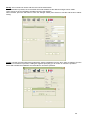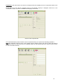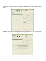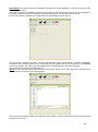
1
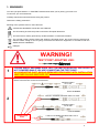
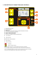
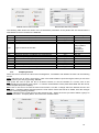
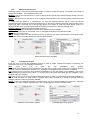
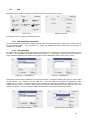
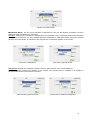
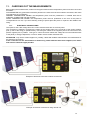
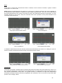
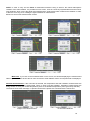
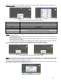
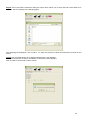
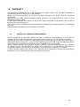
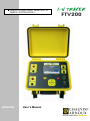
VERIFICATORE CARATTERISTICA I-V MODULI FOTOVOLTAICI ENGLISH ITALIANO User’s Manual 1 1. WARNINGS You have just purchased an I-V TRACER FTV200 and we thank you for placing your trust in us. To best use your new instrument: Carefully read these instructions before using the product. Observe the safety precautions. Meaning of the symbols found on the instrument: ATTENTION, DANGER! Consult the User's Manual. The CE marking ensures the product conforms to European Directives. The instrument is entirely protected by double insulation or reinforced insulation. The crossed out bin symbols means that, within the European Union, the product must be subjected to selective waste sorting for the recycling of electrical and electronic equipment in accordance with the WEEE directive 2002/96/EC. USB port. WARNING! TEST POINT ADAPTER USE: 1 PLEASE VERIFY AND MAKE SURE THAT THE INSTALLATION OR THE CIRCUIT IS NOT POWERED WHILE YOU ARE CONNECTING THE TEST POINT. NO CONDUCTIVE PART SHOULD REMAINED REACHABLE WITH INSTALLATION SWITCHED ON AND SWITCHED OFF. Connect the test points to the installation or the electrical circuit, only after have been combined with relative measurement accessories listed below: ELECTRICAL SAFETY CAT. II 300V Codice P01295458Z 11-0000-276 + P01295458Z: ELECTRICAL SAFETY CAT. II 300V 2 ELECTRICAL SAFETY CAT. III 1000V Code P01295288Z CONDUCTIVE PART 11-0000-276 + P01295288Z: ELECTRICAL SAFETY CAT. III 1000V 2 2. SAFETY PRECAUTIONS The following precautions for use are mandatory instructions for proper use of the instrument. Failure to follow these instructions causes risks such as electric shock, explosion and fire. Meaning of the symbol, WARNING ! please refer to the instructions before using the accessory. Instructions preceded by the symbol above, should they not be carried out as explained, can result in a physical accident or damage to the accessory and installations. In case of improper use of the instrument, safety is compromised and dangerous situations may occur. The internal rechargeable batteries must not be replaced by the user. For internal battery replacement, contact an authorised service centre only. The safety of any system integrated with this instrument is the responsibility of the person who assembles the integrated system. For your safety, use only the cables and accessories supplied with the instrument: they conform to IEC 61010031 (2002). When the sensors or accessories are of a lower category than those of the instrument, the derating must be applied to the entire unit. Before each use, make sure the cables, junction boxes and accessories are in perfect working condition. Every cable, sensor or accessory with damaged insulation (even partial) must be surrendered for repair or eliminated. Do not use the mains power supply when carrying out measurements. The power supply must only be used to recharge the internal batteries, which takes place when the instrument is switched off. Respect the environmental conditions. The use of personal protection devices in accordance with the environmental conditions in which the instrument is used is recommended. This instrument can be used on category III 600V or V II 1000 installations. Never use it on systems that have a voltage or category higher than those indicated. For internal battery replacement, contact an authorised service centre only. These components have specific safety devices; using non-original spare parts could cause serious damage to persons or things. Respect the limits of the physical protections of the accessories and sensors. Do not place your hands on terminals not being used. To clean the external parts, use only a damp cloth, avoid using hydro-carbon based substances or abrasive detergents, and avoid liquids from penetrating the inside of the instrument. 3. NOTES REGARDING THIS MANUAL: The information contained in this manual is subject to variation without prior notice; Although this manual has been written with the utmost care, please contact the manufacturer should you have any comments, opinions or product-related questions; Make sure you fully understand the pre-requisites for use of the product such as the technical characteristics and hardware and software limitations relative to its use. We decline all responsibility for damages resulting from the improper use of the product; Reproduction of this manual, in full or in part, without written permission from our company is prohibited. 3 INDEX 1. WARNINGS ......................................................................................................................................... 1 2. SAFETY PRECAUTIONS .................................................................................................................... 3 3. NOTES REGARDING THIS MANUAL: ................................................................................................ 3 4. INTRODUCTION.................................................................................................................................. 5 5. DESCRIPTION OF CONNECTIONS AND CONTROLS ..................................................................... 6 6. DISPLAY PRESENTATION ................................................................................................................. 7 7. POWER SUPPLY ................................................................................................................................ 7 7.1. BATTERY AUTONOMY .................................................................................................................. 7 7.2. CHARGING THE BATTERIES ........................................................................................................ 7 7.3. MAINS POWER SUPPLY UNIT ...................................................................................................... 7 8. ON/OFF SWITCH ................................................................................................................................ 7 9. IMPORTANT NOTE FOR USE ............................................................................................................ 8 10. DESCRIPTION OF THE MENUS ........................................................................................................ 8 10.1. System ............................................................................................................................................. 8 10.2. Module Archive ................................................................................................................................ 9 10.3. Company Archive .......................................................................................................................... 10 10.4. Measurements Archive .................................................................................................................. 11 10.5. Installations Archive ....................................................................................................................... 11 10.6. USB ................................................................................................................................................ 12 10.6.1. USB-BLUETOOTH ADAPTER ............................................................................................. 12 10.6.2. USB PEN DRIVE .................................................................................................................. 12 11. CARRYING OUT THE MEASUREMENTS ........................................................................................ 14 11.1. ELECTRICAL CONNECTIONS: .................................................................................................... 14 11.1.1.1. Remote Unit .................................................................................................................... 15 11.2. MODULE or STRING ..................................................................................................................... 15 11.3. OTHER FUNCTIONS .................................................................................................................... 20 11.3.1. “FS” Function (full scale) ....................................................................................................... 20 11.3.2. Zoom Function ...................................................................................................................... 20 12. TECHNICAL CHARACTERISTICS .................................................................................................... 21 13. FTV200 PC SOFTWARE ................................................................................................................... 22 13.1. General information ....................................................................................................................... 22 13.2. Installation ...................................................................................................................................... 22 13.3. Using the programme .................................................................................................................... 23 14. WARRANTY ....................................................................................................................................... 31 14.1. SERVICE NOT COVERED UNDER WARRANTY ........................................................................ 31 15. TO ORDER ........................................................................................................................................ 32 4 4. INTRODUCTION The I-V TRACER FTV200 is a measuring instrument designed and built to meet the needs of the technicians during the troubleshooting and maintenance phases of the photovoltaic generator in photovoltaic systems. Photovoltaic systems consist of two main parts: Photovoltaic generator consisting of one or more strings of photovoltaic panels that generate a direct current. Inverter device that converts direct current generated by the panel into alternating current so it can be used in the grid. The I-V TRACER FTV200 has two measurement inputs, one for measuring voltage (V-DC) and one for measuring current (I-DC). Measurements can be taken on a single panel or a string of panels. There are also inputs for the pyranometer sensor and the temperature probe. The temperature probe input accepts both the ambient temperature probe and the contact probe for measuring the temperature of the photovoltaic panels. To facilitate the use of the instrument in difficult conditions, the FTV100 REMOTE UNIT accessory is available which allows connecting the pyranometer sensor and the temperature probe wirelessly, transmitting the sensor measurements to the instrument via BLUETOOTH, via a pair of adapters connected to the respective communication ports. The main measurements taken are: measurement of solar radiation via pyranometer (up to 2000W/m2) measurement of the ambient temperature or panels via Pt100 sensor (up to 120°C) possibility to measure both single panels and strings of panels measurement of the no-load voltage and the MPP voltage (up to 1000 Vdc) measurement of the short circuit current and the MPP current (up to 10 Adc) graphical representation of the I-V curve with marker at the MPP. graphical representation of the power curve with marker at the MPP. comparison of the measurements with the nameplate data of the panels and indication of the result: OK / NO calculation of the efficiency of the solar panels with visualisation of the difference between the nominal value and the measured value 5 5. DESCRIPTION OF CONNECTIONS AND CONTROLS 5 6 1 2 3 7 4 8 1) 2) 3) 4) 5) 6) 7) 8) temperature probe input pyranometer input USB port 2.0 External power supply input (15V DC; maximum absorbed current 2A) 4.3” colour "touch-screen" LCD Monitor Input for voltage measurements Input for current measurements multi-function keypad including the following keys: ▲ : “up” arrow key ► :“right” arrow key OK: button that confirms selection ◄ :"left" arrow key ▼ :"down" arrow key On/off key Return to main menu key BATT Ch LED (only active only with external power supply connected) lit during battery charging, which takes place when the instrument is switched off FULL CH LED INDICATOR (only active only with external power supply connected) lit when the internal batteries have reached their maximum charge 6 6. DISPLAY PRESENTATION The I-V TRACER FTV200 is equipped with a 4.3” colour "touch-screen” LCD display for visualizing the function access icons, the menus and the graphics of the I-V curves of the panel or string of panels measured. Main screen Graph Screen 7. POWER SUPPLY 7.1. BATTERY AUTONOMY The battery icon located in the lower right part of the display represents the battery's charge status. The number of bars in the icon is proportional to the charge level. Battery fully charged. Autonomy: approx. 12 hours Battery semi-charged. Autonomy: approx. 50 minutes Low Battery (flashing symbol) Autonomy: approx. 10 minutes 7.2. CHARGING THE BATTERIES The battery is charged with the INSTRUMENT OFF and with the power supply unit provided with the instrument, connecting it to the dedicated jack. It is recommended that only the power supply unit provided with the instrument be used. This type of power supply unit is specific for the instrument and ensures electrical safety. If the battery is completely discharged, the time required for charging time is approx. 5 hours. 7.3. MAINS POWER SUPPLY UNIT The mains power supply accepts voltages ranging from 90V to 260V-50Hz. The protective fuses are inside the mains power supply unit and not accessible. NOTE: If the fuses are interrupted, do not replace them and send the power supply unit to the service centre for inspection. ATTENTION: use only the mains power supply unit to charge the internal batteries. When using the instrument to carry out measurements, make sure the mains power supply is disconnected. 8. ON/OFF SWITCH To switch on the instrument, press and hold down the button for approx. 2 seconds NOTE: If, when the key is released after start up, the instrument switches off, the batteries are not sufficiently charged. Charge the batteries before use. To switch off the instrument, press and hold down the button for approx. 2 seconds 7 9. IMPORTANT NOTE FOR USE To enter alphanumeric characters in the fields listed in the menus or in specific functions, use the keypad, opened by touching the screen which corresponds to the relative field. To switch the keypad from numeric to alphabetic mode press the (ABC) key in the lower left corner. To switch the keypad from alphabetic to numeric mode press the (.?123) key in the lower left corner. Keypad in numeric mode Keypad in alphabetic mode When it is not possible to use the TOUCH-SCREEN, the keypad on the front panel can be used to select icons and control keys. Use the arrow keys to select icons or control keys; confirm selections by pressing the OK key. 10. DESCRIPTION OF THE MENUS 10.1. System If this icon is selected a window containing the instructions and system settings opens as described below: Serial number: indication of the instrument's serial number. SW Version: indication of the instrument's software version. Power Version: indicates the version of the instrument's measurement firmware. Display: Date and time can always be present on the screen, if the ▼ key is pressed the window opens which allows selecting one of the following conditions: None: the date and time are not displayed. Date – Time: the current date and time are displayed simultaneously. Date: only the current date is displayed. Time: only the current time is displayed. Setting the date and time: in the corresponding field the current date and time are displayed, to edit the date/time select the value to be changed using the ▲ or ▼ keys. Press the "Apply" button to confirm the new settings and exit the menu. Temperature probe: press the ▼ key to open probe type selection window: Module: the measurements are made taking into consideration the temperature of the photovoltaic module. 8 Ambient temperature: the measurements are made taking into consideration the ambient temperature. Remote Unit: If the ▼ button is pressed, the remote unit activation window opens for selecting the connection type between the remote unit and the FTV200 instrument. The possible selections are: Local, the probes are connected without the use of a remote unit. RS-232 Serial Adapter, the BLUETOOTH module is connected to the USB of the instrument by an RS232-USB adapter. Bluetooth Adapter, the connection is via a USB-BLUETOOTH adapter module. When this item is selected, the next two fields are activated for the following settings: Bluetooth Address (MAC), if the corresponding field is selected, a keypad opens for setting the “MAC” number of the Bluetooth adapter used for the remote unit with which you want to communicate. NOTE: : In order for the Bluetooth devices of the instrument and the remote unit to be able to communicate, the MAC number of the Bluetooth adapter used for the instrument must be set in the Bluetooth device used for the remote unit. The PIN code setting of this device must not be activated. To configure the device used for the remote unit, follow the instructions provide in the remote unit's manual. Device name: this setting allows for assigning a name to the Bluetooth adapter used for the instrument. This setting is optional. Pyra Sens. : the sensitivity value of the pyranometer is indicated in the corresponding window. If the set value does not correspond to the pyranometer used or if the pyranometer is replaced, select the window on the and the keypad for setting the new value appears, when the value has been entered, press the "ENTER" button to confirm the new setting and exit the function. Language: press the ▼ key to open the language selection window. Touch the desired language on the screen to confirm the selections and exit. 10.2. Module Archive If this icon is selected a window with the following functions opens: New Module: If this item is selected, the function for inserting the model and plate data of a panel not present in the pre-loaded list is activated. If a new brand must be entered, exit by selecting "Exit" and then select the "Edit Brand" icon. Edit Brand: If this icon is selected a window containing the list of brands present will open; select the "enter new brand" line if you wish to add a brand which is not present in the list. Select the window under the list to write the new name, then select "SAVE" to confirm, select “Exit” to cancel the operation: Working in the same manner as described above it is possible, after selection, to edit the name of an already present brand. Find: if this icon is selected a window opens which allows you to search the list of panels in the memory, according to a selection criterion based on the electrical characteristics. By filling out (even just one) the fields of the main electrical characteristics of the panels, and then pressing the "Search” button, the list of panels corresponding to the setting is displayed. This function, for example, allows for quick verification of the brand and model of the panels that have the selected characteristics. Edit Module: Using this function, after selecting the brand, it is possible to edit and update the model and the values of the electrical characteristics of the panel present in the list. List: If this icon is selected, a window displaying the list of panels and their relative characteristics is opened. Delete: This function allows deleting a brand from the list, as well as all the panels that correspond to it or a single panel. To delete select the brand and possibly the model; press "Delete Model" if you only want to delete the selected model, or "Delete Brand" to delete the brand and all its contents. Press the “Exit” button to return to the previous menu. 9 Module Archive menu window New Module data entry window The following table shows the values of the characteristic parameters of the panels that are entered when a New Module record is created in the database. Symbol Pmax Vmpp Voc Description Maximum nominal power of the module Voltage at maximum power point No-load voltage Type Type of silicone of the cells Beta Toll – NOCT Impp Isc Alpha Gamma Toll + Voc temperature coefficient Negative tolerance provided by the manufacturer Nominal operating temperature of the cell Current at maximum power point Short circuit current Isc temperature coefficient Pmax temperature coefficient Positive tolerance provided by the manufacturer Unit of measurement (W) (V) (V) (%/°C) (%) (°C) (A) (A) (%/°C) (%°C) (%) Range 1.00 to 1000.0 1.00 to 200.0 1.00 to 200.0 Monocrystalline Polycrystalline Thin Film Amorphous Micromorph - 1.00 to - 0.0001 0 to -50 0 to 100 0.2 to 10.00 0.2 to 10.00 - 0.200 to + 0.200 - 1.00 to -0.01 0 to +50 10.3. Company Archive Select this icon to access the client record management, consultation and deletion functions via the following menus: New: select this icon to enter a new record. Click in the relative fields to open the keypad, when you are done typing confirm your entry by pressing “ENTER”. List: press this icon to open the list of all stored records, to view the details of a record, click on the corresponding line and then press “Open”. To view the characteristics of the plants associated with the record, select the plant and press "Display". Edit: click on this icon to access the edit record function; to make a change select the desired record in the “Surname – Company Name” field and press the “Edit” button. Select the field to be edited, enter the changes and the confirm by pressing "ENTER". Delete: select this icon to open the list of the stored records. Select the record you wish to delete, typing it in the field "Surname - Company Name" and click on the "Delete" button. Company Archive Menu Window Company Details Window 10 10.4. Measurements Archive Press this icon to access the measurements archive in order to consult and cancel, if necessary, the records of measurements taken. The available functions are: Modules: click on this icon and then on "List" to display all the records of the measurements carried out on the individual panels. Strings: click on this icon and then on “List” to display all the records of the measurements carried out on the strings. To switch from the graph to a measurement, for both the modules and the strings, select the desired measurement from the list by touching the desired item on the screen and then select the "Graph" button. When viewing the graph, command "FS" in the top right allows you to switch to graph full screen display mode or to display both the graph and the command bar at the bottom of the screen, with the following items: Module or String: displays the electrical data measured. Environment: displays the ambient measurements: temperature and radiation. Power: displays the OPC or STC power curve on the graph depending on the selection made. Exit: return to previous menu. Delete: clicking on this icon after selecting “Panels” or “Strings” you enter measurement record delete mode. To delete a record, select the desired line and then press "Delete" Measurements Archive Windows 10.5. Installations Archive Press this icon to access the installations archive in order to create, manage and delete, if necessary, the measurement records. The available functions are: New: select this icon to enter the new installation entry window. If the fields of the respective items are selected, the data entry keypad opens; when you are finished entering the data, confirm by pressing the "ENTER" key. Repeat the same steps for each field to be completed. List: press this icon to open the list of all stored installations, to view the details of an installation, click on the corresponding line and then press “Open”. To view the data of the plants associated with the installation, select the plant and press "Display". Edit: click on this icon to access the edit installation function; to make a change select the desired installation in the “ID” field and press the “Edit” button. A keypad opens when the field to be edited is selected; enter the changes and then confirm by pressing "ENTER". Delete: if this icon is selected a window opens from which the list of stored installations is accessed. Select the installation you want to delete, highlighting it in the "ID" field and then click the "Delete" button. Installation Archive Menu Window Installation Data Entry Window 11 10.6. USB Select this icon to access the USB port management menu and its relative controls. Main screen USB menu screen The USB is used to manage the following devices. 10.6.1. USB-BLUETOOTH ADAPTER this device allows the instrument to communicate with the FTV100 Remote Unit” to obtain the measurements of the atmospheric probes. The instructions for setting the USB-BLUETOOTH ADAPTER are described in Chapter 10.1 “System”. 10.6.2. USB PEN DRIVE the USB memory is used to transfer the archives (measurements or settings) from the instrument to the PC and vice versa. The operations are made selecting the "Copy to.." or "Copy from.." controls; once the selection is made a window appears on the screen for the selection of the destination folder or the "source" folder. "Copy from..." message box "Copy to..." message box The pen drive is also used to update the instrument's firmware. To make the update make sure you have copied the file with the "upg. extension onto the USB key. Once the USB key connection is established, select "Update" from the menu; a window appears on the monitor for selecting the update file. Select the file to be loaded and then click on "Confirm". The progress bar indicates the progression of the update and once the update is complete, you are prompted to restart the instrument. Press OK to finish the procedure. File selection window Update progress bar window 12 Restart command window IMPORTANT NOTE: For the correct operation of USB devices, carry out the following commands, once the USB to be used is inserted in the connector: Connect: clicking on this command, a window opens for confirmation of the connection between the instrument and the device inserted in the port, USB-BLUETOOTH ADAPTER or USB PEN DRIVE. During the inserted device's connection phase, an indicator of the progress of the connection appears on the monitor. Connection message box Connection progress window Disconnect: selected this command to start the “secure” disconnection of the connected device. The disconnection progress bar appears on the monitor; once disconnection is complete, it is possible to disconnect the device in use from the connector. Disconnection progress window Disconnection complete message box 13 11. CARRYING OUT THE MEASUREMENTS Before taking the measurements, make sure the pyranometer and the temperature probe have been connected as follows: PYRANOMETER: the pyranometer should be placed on the same level as the modules to be tested; also make sure that there are no shadows. AMBIENT TEMPERATURE PROBE: the temperature probe must be positioned in a shaded area that is sufficiently ventilated and near the modules. PANEL TEMPERATURE PROBE: the temperature probe must be positioned on the rear of the panel in correspondence to a cell; if you are measuring a string of panels place the probe on a panel in the middle of the string. 11.1. ELECTRICAL CONNECTIONS: The inputs for the V-DC voltage and I-DC current measurements are on the front panel. The connection is made by connecting the cables of the positive pole to the connector of the panel's positive pole (or that of the string) in parallel and by connecting the cables of the negative pole to the connector of the panel's negative pole in parallel. This type of 4-wire connection makes the voltage and current measurements of the panel (or string) independent, in order to obtain more accurate measurements. ATTENTION: only use the cables supplied or, possibly, cables with suitable characteristics and certifications for the electrical connections. If the connection for the measurement is made using cables different than those supplied, use cables that have the shortest length possible. Example of electrical connections without remote unit Example of electrical connections using remote unit 14 11.1.1.1. Remote Unit Because of the size of the plant, you may need to place the instrument in a location far from the photovoltaic panels (for example: an integrated plant on the roof with impossibility of having electrical connection on the same level of modules or strings). Thanks to the FTV 100 remote unit (option), to be installed next to the photovoltaic panels, it is possible to transmit in a REAL TIME the measures of radiation, ambient temperature and panels temperature (by the Bluetooth kit) to the instrument. This will allow you to achieve a very simple and accurate testing and also display and store measures at the same time. How to measure using the remote unit: - Place the remote next to panels. Connect the Bluetooth adapter with the included RS232 cable, the temperature probe (module or environment) and the parallel pyranometer to the module or string. - Turn on the remote unit by switching ON (green LED ON). The power green LED of the Bluetooth adapter will be lit (if no please move the selector located on the side in “ pores” position). The remote unit now is ready to transmit measures to the I-V TRACER FTV200 instrument. How to program the I-V TRACER FTV200 instrument to use with the remote unit: - Turn on instrument and go to “System” menu. Choose the Unit Remote – Bluetooth Adapter option. Insert in Bluetooth Address (MAC) option the MAC number showed on the BLUETOOTH RS232 connected to the remote unit. - Click on “Apply” to confirm the above. - Insert the USB-BLUETOOTH into the USB port. Meter is now ready to receive the measures of the remote unit. The led drive of the USB-BLUETOOTH will light only activating the measure from “MODULE” or “STRING” menu. 11.2. MODULE or STRING The measurement functions are as follows: Module: to measure a single panel, select the “Module” icon from the main menu, String: to measure a string of panels, select the “String” icon from the main menu, Main menu screen If the Module or String icon is selected from the main menu, the connection diagram appears on the screen; if "Continue" is pressed, the graph is displayed. In this way the measurement functions for a single panel or string of panels are activated (the type of measurement selected is displayed at the top centre of the screen). Independently of the selection made, the control buttons under the graph allow you to manage the measurements as described below: 15 Start: If this button is pressed the measurement session is started; once the session is finished, a graph is created showing the "I-V" curve in red. NOTE: Before the measurements are carried out, a test is run to verify the presence and correct operation of the temperature probes (ambient or module) and solar radiation (pyranometer). If an error occurs while during the probe measurements or the remote connection (if active), the measurement session is interrupted. An error message appears on the screen; verify the connection and correct operation of the probe indicated or the connection to the remote unit. Single panel measurement window Error message box Error message box Panel measurement graph If "STRING" measurement has been selected, before the measurements are carried out, a dialog box opens in which the number of panels that make up string to be tested must be entered. String of panels measurement window Panel number entry window Comparison: If this button is pressed, a window opens for entering the brand and model of the panel measured in order to run the comparison between the measurements and nameplate data; the measurements obtained will appear along with nominal characteristics of the panel. For greater accuracy in comparison, the age and corresponding presumed percentage of panel performance degradation are requested; if you do not want to enter these data, press the "Do not apply" button. 16 Reference panel selection window Ageing values entry box After choosing the panel settings, the results of the comparison are shown in the lower left corner of the graph as follows: Measurements @ STD – NO The result of the comparison is negative; the electrical values measured do not fall within the range of nominal values of the panel (or the string). Measurements @ STD – OK The result of the comparison is positive; the electrical values measures fall within the range of nominal values of the panel. Measurement graphs with comparison results NOTE: If the negative result of a test refers to measurements carried out on a string of modules, each individual module must then be measured in order to identify the faulty module or modules of the string. Measurements: Press the "Measurements" function on the command bar below the graph to access the menu for the following functions: Rs: use this command to activate the Series Resistance measurement function. Series resistance is measured only on individual modules and, as set out in standard IEC/EN 60891; it is measured in two phases, in different conditions of solar radiation. The first measurement must be taken with a solar radiation value greater than 500 W /mq. The second measurement must be taken with a lower solar radiation value; the difference between the two values must be at least 50 W/mq. The conditions necessary to ensure that the measurements are correct are controlled automatically by the instrument. The measurements taken will later be saved along with the measurements of the I-V curve in the panel tab, using the procedure described in the Save paragraph. To carry out the measurement, proceed as follows: After the Rs function is selected, there are two commands associated with it: Calculation: if this button is pressed phase 1 of the measurements starts; a window appears on the monitor that highlights the radiation value measured and the "Phase 1 Measurement" button. If this button is pressed, the measurements are taken. If the solar radiation value is not conforming, a warning message will appear on the screen. After the phase 1 measurements are taken, a window with a "Phase 2 Measurement" button appears. If this button is pressed and the solar radiation condition is correct, the second measurement session begins; otherwise, a warning message appears on the screen. In this case you must wait for the solar radiation conditions come within a suitable range as previously described. Once the, these conditions have been reached, the second phase of measurement can be repeated. 17 NOTE: In order to carry out the Phase 2 measurement without having to wait for the natural atmospheric variation of the solar radiation, it is possible to use a screen, such as a sheet of polycarbonate like those used in shop windows, which covers the panel being tested and the pyranometer which measures the radiation in order to filter the sun's rays, thus creating the right conditions for measurement. Below is a series of Rs measurement screens Measured: if you click on the measured button on the screen, the window displaying the measurement taken is opened. In the window the Rs value and the two solar radiation values of test performed are displayed. Ambient measurements: If this command is selected, the temperature and solar radiation measurements are displayed. With reference the options Mod. Temp. or Amb. Temp are available. Indicates if measurements are being carried out using the module temperature probe or the ambient temperature probe (previously selected). The Remote Connection message...is present whenever the probes are connected via the remote unit. Images of the Measurements Environment Windows 18 Module (or String): if this command is selected, the “Electrical Data Measured” table is displayed. The following image shows the measurements table screen. Images found in the Electrical Data Measured window. Parameter Description Pmax Max. power of panel/string measured by the instrument Vmpp Voltage at maximum power point Impp Current at maximum power point Voc No-load voltage Isc Short circuit current Fill Factor % (ratio between the measured maximum power and no-load) Deviation% of the maximum power measured by the nominal power (@ STC) FF DPmax Power: This command allows the power curve of the panel of string measured to be represented on the I-V graph of the panel or string. The window that opens using this command, allows you to select the power curve to be displayed, from the following two options: OPC: the power curve measured and the measurements carried out for the I-V curve are represented on the graph at the same time. STC: the power curve that refers to the standard test conditions is represented on the graph; these are the same conditions used to obtain the nameplate data of the photovoltaic modules. NOTE: the STC selection button is present only after the brand and model of the panel of comparison. Representations of the OPC and STC power curves Salve: press the Save button to access the measurement saving function. The window that opens for this function allows you to enter a comment which is saved in the measurements tab. Press the Save button in the dialog box to save the measurements and the comment. The saved measurements can be displayed using the "Measurements Archive" Menu, accessed via the main menu (page 9 of Chapter "MEASUREMENTS ARCHIVE"). Dialog box for saving the measurements 19 11.3. OTHER FUNCTIONS 11.3.1. “FS” Function (full scale) Use the FS button in the upper right of the monitor when the graphs are displayed, to switch to full-screen mode. In this way, the greater height of the graph allows for a larger view. To return to the normal viewing mode, press the FS button again. Full-screen visualisation 11.3.2. Zoom Function Using the zoom function it is possible to enlarge a portion of the graph to allow for a more detailed analysis of a given part of the curve shown. To use the zoom function, touch the screen using the stylus and drag to highlight the portion of the graph you wish to enlarge. During this operation, a white rectangle is drawn on the screen which guides the definition of the area you wish to enlarge. If the stylus is removed from the screen, the zoom mode is automatically activated and the previously defined area is displayed in full-screen mode. On the upper right of the screen, above the Full-Screen (FS) function button, there are two command buttons for managing the zoom function. These buttons are: In: each time this button is pressed, the magnification increases. Out: each time this button is pressed, the magnification decreases until “normal” visualisation is restored. 20 12. TECHNICAL CHARACTERISTICS DISPLAY 4.3” COLOUR GRAPHIC LCD WITH BACKLIGHT AND TOUCH-SCREEN RESOLUTION 480 x 272 BRIGHTNESS 500 cd/mq CONTRAST 400:1 MEASUREMENTS METHOD RANGE ACCURACY RESOLUTION SOLAR RADIATION THERMOPILE PYRANOMETER 0 to 2000 W mq < 3% 1 W mq AMBIENT TEMP. PT100 PROBE -20 to +100 °C < 2% ± 1 °C 0.1 °C MODULE TEMP. PT100 PROBE -20 to +100 °C < 2% ± 1 °C 0.1 °C VOLTAGE DC VOLTMETER 10 to 1000 V; ± 1% 0.1 V CURRENT DC AMMETER 0.1 to 10 A; ± 1% 0.01 A POWER I-V MEASUREMENT 10 W to 10 KW ± 1% 0.1 W SERIES RESISTANCE I-V MEASUREMENT 0.1 Ω to 100 Ω < 2% ± 0.1 Ω 0.01 Ω I-V GRAPH I-V CURVE OF THE PANEL or STRING OF PANELS MPP GRAPH POWER CURVE WITH MARKER ON MPP POINT DATA LOGGER RECORD STORAGE INCLUDING: CLIENT DETALS, PLANT CHARACTERISTICS, GRAPHS INTERNAL MEMORY CAPACITY 80 MB FOR A TOTAL OF 10,000 RECORDS. POSSIBILITY TO USE "USB" EXTERNAL MEMORIES COMMUNICATION PORT USB 2.0 INTERNAL POWER Li-Ion BATTERY PACK 16V 4.5 Ah MAX ABSORPTION DURING USE 0.6 A MAINS SUPPLY EXTERNAL POWER SUPPLY 220-V ac 50Hz with 3-pole network cable and SHUKO plug OUTPUT 16V 3.8A dc MAX ABSORPTION IN BATTERY CHARGE MODE 2 A POWER Operating ambient temperature - 5 to + 40 °C. Max. operating altitude 2000 m. Relative humidity 80% AT MAX OPERATING TEMPERATURE Storage temperature -10° to + 60 °C. PROTECTION CONSTRUCTION SITE CONTAINER IP54 PROTECTION (WITH LID CLOSED) DIMENSIONS 270 X 250 X 130 mm WEIGHT APPROX. 2.5 KG (BATTERY INCLUDED) 21 13. FTV200 PC SOFTWARE 13.1. General information The FTV200 PC SOFTWARE is an application package installed on the PC which allows you to manage the same archives present on the instrument. Using this application it is possible to import the records of the measurements and their relative graphs so they can be printed or used depending on the user's requirements. In addition, it is possible to prepare the "Installation" records and the "Company" records, edit or update the Database of the modules and then transfer the new data to the instrument. 13.2. Installation The software is automatically installed when the CD supplied is inserted. If your PC is no set up to automatically start the CD, click on My Computer from the start menu and then right click on "CD ROM Unit" and select Open by clicking left and the window displaying the contents of the CD will open. Click on the “FTV200_SETUP icon twice to start the installation. Language selection is prompted first. Select the desired language and press OK to continue. Follow the instructions that appear on the monitor until the installation procedure is complete; when the procedure is complete, the start programme icon will be available on the desktop. Desktop Icon 22 13.3. Using the programme When the programme is started the main window appears, as shown in the figure below. On the command bar in the upper left of the window are the buttons for the following functions: Modules: press this button to access the archive where the Brand and Module folders are located. Selecting the Brand folder allows you to enter a new brand, edit a brand on the list, and delete a module brand and all the models associated with it. Selecting the module folder, you can enter, edit and delete data for a single panel selected. Press close to return to the main screen. 23 Measurements: if this button is pressed the measurements archive folder opens as shown in the following image. This window displays the list of stored measurements; select a measurement on the right to display the "Electrical Data Measured", the "Ambient Measurements" recorded when the electrical measurements were being taken and the results of the comparison between the measurements obtained with the standard characteristics of the module (of the string). The commands located under "Curve Selection" allow you to select the curves that you wish to display by ticking the corresponding box. After making your selection, press the "Graph" button on the screen to pen the graph window. Right click on the mouse on the area of the graph desired; a contextual menu opens which allows you to print the graph or perform other operations allowed. Export: if you click this button, the selected measurement and relative graph are saved in Excel format. Follow the PC's operating system instructions to finish saving the file. Delete: the “Delete” command is used to eliminate the selected measurement from the list. If this button is pressed, a dialog box appears on the monitor which allows you to confirm (YES button) or cancel (NO button) deletion. 24 Installations: press this button to access the installations tab; the list of installations stored in the database is displayed. On the right part of the tab the complete record of the selected installation is displayed; under this, in the "Measurements" section is the list of measurements belonging to this record. Picture of the Installations tab The commands present under the installations list allow you to perform the following operations: New: this command is used to enter a new installation and its relative record in the archive. When the button is pressed the fields are cleared and can be completed. When you are finished click OK to save the new record or Cancel to exit without saving. 25 Modify: this command is used to edit the record of the selected tab. When the button is pressed, the record fields are made available so the desired changes can be made. Use to mouse to click in the field to be edited and type the changes. When finished, press the OK button to save the changes made: press Cancel to exit the edit function without saving. Delete: use this command after having selected a specific installation from the list in order to delete it from the database. If the button is pressed, a dialog box appears prompting you to confirm of cancel the operation. Select OK to delete the installation and select NO to cancel the operation. 26 Companies: press this button to access the companies tab which displays the list of companies stored in the database. On the right part of the tab the complete record of the selected company is displayed; under this, in the "Installations" section is the list of installations belonging to this record. Picture of the Companies tab The commands buttons present under the list of companies allow you to perform the following operations: New: this command is used to enter a new company and its relative record in the archive. When the button is pressed the fields are cleared and can be completed. When you are finished click OK to save the new record or Cancel to exit without saving. 27 Modify: this command is used to edit the record of the selected company. Clicking on the command, the record fields are made available so the desired changes can be made. Use to mouse to click in the field to be edited and type the changes. When finished, press the OK button to save the changes made: press Cancel to exit the edit function without saving. Delete: use this command after having selected a specific company from the list in order to delete it from the database. If the button is pressed, a dialog box appears prompting you to confirm of cancel the operation. Select OK to delete the installation and select NO to cancel the operation. 28 Import/Export: this function is used to manage the transfer of the entire database, or part of it, from the PC to a pen drive or vice versa. Using this procedure it is possible to transfer the new settings of the various tabs, from the PC to the instrument. The same procedure is used to transfer the measurement archives from the instrument to the PC. If the function button is pressed, the window shown in the following image is opened. The tab shows 5 database sections: Module measurements, String measurements, Modules, Installations, Companies. Next to each section there is a selection box which allows you to choose the part of the database you want to manage; the check symbol indicates that the corresponding item has been activated. The commands for managing the database are: Import: if this command is selected a dialog box opens which allows you to select the path of the folder to be imported. See the example in the following figure. Once you have selected the folder to be imported, click on Open. To finish the procedure, follow the instructions provided on the screen. 29 Export: if this command is selected a dialog box opens which allows you to select the path of the folder to be exported. See the example in the following figure. After selecting the destination, click on Save. To finish the procedure, follow the instructions provided on the screen. Delete: this command allows you to delete selected items in the database. When the command is clicked, a cancellation confirmation window appears. Click on YES to confirm and on NO to cancel. 30 14. WARRANTY The instruments manufactured by us are guaranteed for twelve months from any faults attributable to manufacturing defects or defects in the used materials. Revision and servicing operations are carried out by Technical Support at our facility, where the instruments must be sent. Shipment must be freight paid with adequate packing, preferably in the original packing in order to prevent damage during transportation. In order to take advantage of the warranty a copy of the invoice or fiscal sales receipt relative to the purchase of the instrument must be produced. The warranty will be considered void in case of tampering, modifications or repairs carried out by unauthorised personnel. The power batteries and piles are not included in the warranty. 14.1. SERVICE NOT COVERED UNDER WARRANTY We are available for our esteemed customers for repair of instruments manufactured by us, even after the warranty period, to restore the equipment to its original condition (as long as it is economically convenient). Availability of mechanical and electronic replacement parts is guaranteed for up to 5 years when the circuits are realised with discreet components. In the event that integrated circuits are used, supply of replacement parts is ensured while our supplies last and subordinate to their availability on the global market. Repair of instruments which are no longer in warranty is normally carried out against payment. Any request for an estimate must be done expressly upon delivery of the instrument. In the event that the estimate is not accepted, the expenses sustained by us for preparation of the same will be charged to the customer. In order to prevent pointless loss of time it is very important that the equipment is returned with accompanying documents in order complete with all of the data as required by the law. 31 15. TO ORDER I-V TRACER FTV 200 Code P01160740 The instrument is supplied in a hard carry case: 3m cable set (R/N) with MC4 compatible connectors 1 magnetic stylus for touch-screen 1 set of 2 test point (1R/1N) Flex, to be used only with cables supplied 1 pyranometer for solar radiation + 5m connection cable 1 Pt100 ambient temperature probe 3m 1 Li-Ion + mains power supply Data transfer software and user’s manual included into usb-key Certificate of compliance Carrying case for accessories Instructions manual in Italian I-V TRACER FTV 200 Code P01160745 The instrument is supplied in a hard carry case: 3m cable set (R/N) with MC4 compatible connectors 1 magnetic stylus for touch-screen 1 set of 2 test point (1R/1N) Flex, to be used only with cables supplied 1 Li-Ion + mains power supply Data transfer software and user’s manual included into usb-key Certificate of compliance Carrying case for accessories Instructions manual in Italian OPTIONAL ACCESSORIES FTV100 REMOTE UNIT + 2 RS232 connectors male/male Code P01160736 Bluetooth communication kit (transmitter / receiver – already programmed) Code P01160739 1 Pt100 probe for panel temperature Code P01160732 SPARE PARTS 1 pyranometer for solar radiation + connection cable Code P01160730 1 Pt100 probe for ambient temperature Code P01160731 1 Pt100 probe for panel temperature Code P01160732 Li-Ion battery 14.8V 4.5Ah Code P01160735 Magnetic stylus Code X02934A00 Carrying case for accessories Code P01298066 32 10 – 2011 NF GB 551 Ed. 1 of 10/2011 DEUTSCHLAND - Chauvin Arnoux GmbH Straßburger Str. 34 - 77694 Kehl / Rhein Tel: (07851) 99 26-0 - Fax: (07851) 99 26-60 ESPAÑA - Chauvin Arnoux Ibérica S.A. C/ Roger de Flor N° 293, Planta 1- 08025 Barcelona Tel: 902 20 22 26 - Fax: 934 591 443 ITALIA - AMRA SpA Via Sant’Ambrogio, 23/25 - 20846 Macherio (MB) Tel: 039 245 75 45 - Fax: 039 481 561 ÖSTERREICH - Chauvin Arnoux Ges.m.b.H Slamastrasse 29 / 2 / 4 - 1230 Wien Tel: 01 61 61 961-0 - Fax: 01 61 61 961-61 SCANDINAVIA - CA Mätsystem AB Box 4501 - SE 18304 TÄBY Tel: +46 8 50 52 68 00 - Fax: +46 8 50 52 68 10 SCHWEIZ – Chauvin Arnoux AG Einsiedlerstraße 535 - 8810 Horgen Tel: 044 727 75 55 - Fax: 044 727 75 56 UNITED KINGDOM – Chauvin Arnoux Ltd Waldeck House - Waldeck Road - Maidenhead SL6 8BR Tel: 01628 788 888 - Fax: 01628 628 099 MIDDLE EST – Chauvin Arnoux Middle Est P.O. BOX 60-154 - 1241 2020 JAL EL DIB (Beirut) - LEBANON Tel: (01) 89 04 25 - Fax: (01) 89 04 24 USA - Chauvin Arnoux Inc - d.b.a AEMC Instruments 200 Foxborough Blvd. - Foxborough - MA 02035 Tel: (508) 698-2115 - Fax: (508) 698-2118 CHINA – Shangai Pu-Jiang – Enerdis Instruments Co.Ltd 3 F, 3 rd Building - N° 381 Xiang De Road - 200081 SHANGHAI Tel: +86 21 65 21 51 96 - Fax: +86 21 65 21 61 07 http://www.chauvin-arnoux.com http://www.amra-chauvin-arnoux.it 190, rue Championnet - 75876 PARIS Cedex 18 - FRANCE Tél.: +33 1 44 85 44 85 - Fax: +33 1 46 27 73 89 - [email protected] Export: Tél.: +33 1 44 85 44 86 - Fax: +33 1 46 27 95 59 - [email protected] 33