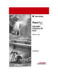
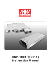
1
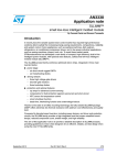
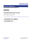
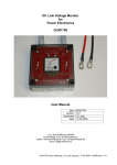
Installation/Operation Manual
Model: Scout Power System, 12V
Features
•
•
•
•
•
•
•
•
•
1 RU low profile, 19 inch rack mounting
Programable digital controller and system monitor
Front panel LCD display provides system status
USB, RS-232 or Ethernet interface for PC connection
locally or remote monitoring and control via modem
Alarm/event log with time and date
Windows based PC communication software
Easy wire connections on rear panel
4 user programmable relay outputs for traditional remote
monitoring or warning
2 year waranty
M-Scout-SLF
As of 102014
P.O. Box 1306
Newport Beach
California 92663
www.newmartelecom.com
Phone: 714-751-0488
Fax: 714-957-1621
E-Mail: [email protected]
Table of Contents
Section
P.O. Box 1306
Newport Beach
California 92663
Page
Quick Reference Guide......................................................................
0
0. Safety Guidelines...........................................................................
1
1. Materials Provided.........................................................................
1
2. Quick Start Installation/Wiring/Set-Up...........................................
1
3. Functions........................................................................................
2
3.1 Scout Monitoring Functions......................................................
2
3.2 LED Indicators and LCD User Interface...................................
2
3.3 Communication and Operation Interface..................................
2
3.4 Real Time Clock, Data Log and Event Log..............................
2
3.5 Programmable Relays and Digital Input Signals......................
2
3.6 Alarms......................................................................................
3
3.7 PMBus Communication Interface.............................................
3
4 Scout LCD User Interface...............................................................
3
4.1 Description of SCOUT Front Panel..........................................
4
4.2 Status Menu.............................................................................
4
4.3 Settings Menu..........................................................................
4
4.4 Maintenance Menu..................................................................
6
4.5 Network Menu..........................................................................
6
5. Scout-S Web Page Monitoring Functions......................................
7
5.1 IP Settings of PC......................................................................
7
5.2 Description of Scout-S Built-in Web Page................................
9
5.3 Event Log Page.......................................................................
12
5.4 Data Log Page.........................................................................
13
5.5 TCP/IP Configuration Page......................................................
13
6. Scout-S Monitoring Software.........................................................
14
6.1 Installation..................................................................................
14
6.2 Using RS232 for Communication with Scout-S........................
15
6.3 Description of Scout-S Monitoring Software.............................
15
7. GSM Short Message Functions.....................................................
22
7.1 Installation and Settings............................................................
22
7.2 Test of Sending a Short Message.............................................
23
7.3 AT-Command List for Scout-S....................................................
23
8 EMI Suppression Arrangement.......................................................
23
9. Troubleshooting..............................................................................
23
10. Warranty and Contact Information...............................................
23
Appendix A - J...................................................................................
24
www.newmartelecom.com
Phone: 714-751-0488
Fax: 714-957-1621
E-Mail: [email protected]
Quick Reference Guide
Front Panel View
Power Module B
Power Module A
LED
Indicators
Pg. 2
LCD Display
Pg. 2
USB Port
Controller
Esc Down
Ent Up
Controller Programming
Buttons, Pg. 3
Rear Panel View
1
App. F
2
Pg. 15
Digital Input
Pg. 2
Ethernet
Pg. 7
AC Power Input
Module“A”, Pg. 1
+
4
Pg. 2
5
Pg. 1
6
Pg. 1
AC Power Input
Module“B”, Pg. 1
DC Output
Pg. 1
7
Pg. 3
Chassis
Ground
Pg. 1
Rear Panel References
1)RJ45 Port (JK-1) used when paralleling multiple shelves
2)RS-232 Port (DB9) - SMbus output for system monitor
3)Digital input for integrating auxiliary alarms
4)Form C programmable alarm relay contacts (RY1 RY2 RY3 RY4)
5)12 VDC power feed to controller (provided by rectifier output)
6)DB 25 connector - mating connector RKP-1U must be installed for system operation
7)Power module address setting for serial SMBus for remote monitoring,
Factory preset: Module A on-on-on-on-on
Module B off-on-on-on-on
0
P.O. Box 1306
Newport Beach
California 92663
www.newmartelecom.com
Phone: 714-751-0488
Fax: 714-957-1621
E-Mail: [email protected]
0. Safety Guidelines
• Risk of electrical shock and energy hazard. All failure should be examined by a qualified technician.
Please do not remove the case cover from the unit
• Please do not change any component on the unit by yourself or make any kind of modification on it
• Please do not install the unit in places with high moisture, high ambient temperature or under direct sunlight
• Please do not feed in voltage that is over or less than 10% of the rated value. Refer to the safety label on the unit
• The safety protection level of this unit in class 1. As a result, the “Frame Ground” on the rear of the racks unit must
be well connected to earth ground. The total leakage current of the whole system, including two Scout Rectifiers
(Scout-R), is less than 2.3mA
1. Materials Provided
Materials Provided with Shelf*
Quantity
Description
1
Scout-S System Shelf
2
19” Mounting Ears
4
10/32 x 3/8” Flat Head Mounting Ear Screws
2
1/0 AWG Termnal Lugs
1
Rectifier Blank Plate
8
10/32 x 3/4” Load Screws
1
RKP-1U Connector (must be installed for system operation)
1
PC Cross-Over Cable
1
Installation/Operation Manual Short Form
* Note, AC power cord provided in box with rectifier
2. Quick Start Installation/Wiring/Start-up
1) Attach rack mounting ears to shelf using the provided #10-32 x ¾” flat head screws.
2) Install in a 19” rack with a minimum of 4” clearance from front and back of shelf to allow for adequate fan ventilation
(for installation in a 23” rack, contact Newmar and request SRS-1U 23” adapter set).
3) Insert power modules in shelf, and blank plate provided if only one power module is installed. Ensure that the securing
latch located on left edge of rectifier face clicks in to place.
4) Plug in power cords provided with rectifiers into IEC sockets at rear of shelf. Rectifiers accept universal input
90-264 VAC 46-63 Hz. Maximum current draw per rectifiers is 13 amps @ 115 VAC / 7 amps @ 230 VAC. Remove
and replace the NEMA 5-15 end plug if necessary to match the outlet configuration at your site. If replacing, the power
cord utilizes 14 AWG minimum wire size for 115 VAC input or 16 AWG for 220 VAC input.
5) Attach DC output wiring directly to 12 volt load, distribution panel or battery. Lugs for 1/0 wire are provided for bulk
output connection, or attach multiple smaller gauge cables if necessary for your wire routing configuration. Reference
table 1 wire size guide. When making a connection to a battery install a fuse on the +12 VDC side (Hot) as close to the
battery terminal as practical.
6) Connect interface cable(s) (USB/RS 232), programmable relays, digital input signals depending on your application.
7) Install RKP-1U in location 6.
8) Power on system: LCD read out on front panel will display system data, use key pad buttons to scroll through menu
and make settings.
1
P.O. Box 1306
Newport Beach
California 92663
www.newmartelecom.com
Phone: 714-751-0488
Fax: 714-957-1621
E-Mail: [email protected]
6&2876/6&2875
)NSTALLATION/PERATIONManual
0.Safety Guidelines
Riskofelectricalshockandenergyhazard.Allfailureshouldbeexaminedbyaqualifiedtechnician.Pleasedonotremovethe
casefromtheunit.
Pleasedonotchangeanycomponentontheunitbyyourselformakeanykindofmodificationonit.
Pleasedonotinstalltheunitinplaceswithhighmoisture,highambienttemperatureorunderdirectsunlight.
Pleasedonotfeedinvoltagethatisoverorlessthan10%oftheratedvalue.Refertothesafetylabelontheunit.
ThesafetyprotectionlevelofthisunitisclassI.Asaresult,the"FrameGround"( )ontherearoftherackunitmustbe
wellconnectedtoearthground.Thetotalleakagecurrentofthewholesystem,includingtwR6FRXW5units,islessthan
2.3mA.
1. Introduction
The6FRXW6isadedicatedmonitorunitfor6&28759$PS5HFWLILHUV.Itprovidesthemanagementtaskof
6FRXW5forusHintelecommunication,monitoringsystems,servers,etc.Itcanbestand-aloneoperatedorintegratedintoa
19-inchrack.
1.2 Features
1Ulowprofile/19-inchrackmounting.
Controlandmonitor6FRXW5units.
FrontpanelLCDandbuttonsforon-siteservicewithoutPC.
USB,RS-232,orEthernetinterfaceforPCconnectionlocallyorremotemonitoringandcontrolviaGSMmodem.
Alarm/eventlogwithtimeanddate.
Windows-basedPCcommunicationsoftware.
Easywireconnectionsonrearside.
4userprogrammablerelayoutputsfortraditionalremotemonitoringorwarning.
yearswarranty.
USB
4XLFN6WDUW
$&ZLULQJ
$Q,(&&VW\OHSRZHUFRUGZLWKVWDQGDUG9$&$SOXJLVSURYLGHGZLWKHDFKUHFWLILHU,I\RXUHTXLUHDGLIIHUHQWSOXJHQGWKLVSOXJ
FDQEHFXWRIIDQGWKHFRUUHFWSOXJHQGIRUWKHRXWOHWDW\RXUVLWHDWWDFKHG5HFWLILHUVKDYHXQLYHUVDOLQSXWRIYDF+]
0D[LPXPDFFXUUHQWGUDZLV$PSV#YDFRU$PSV#YDF
'&ZLULQJ
&RQQHFWWKH6FRXW6VKHOI'&RXWSXWWHUPLQDOVXVLQJWKHKDUGZDUHSURYLGHGWRHLWKHUWKHORDGYGFORDGGLVWULEXWLRQSDQHORU
GLUHFWO\WRDYGFEDWWHU\:HUHFRPPHQGDEDWWHU\IXVHEHLQVWDOOHGDVFORVHWRWKHEDWWHU\+27WHUPLQDODVSUDFWLFDO6L]HWKHIXVH
WRSURWHFWWKHZLUHVL]HFKRVHQ:HUHFRPPHQGIXVHYDOXHRIRIPD[LPXPFXUUHQW
6FRXWFRQWUROOHUSRZHUQRWH7KHLQSXWSRZHUIRUWKHFRQWUROOHULVSURYLGHGYLDDPP,'PP2'EDUUHOSOXJRQWKHUHDUSDQHO
6.7KHSRZHUVRXUFHLVSUHZLUHGIURPWKHIDFWRU\WRDOORZWKH6FRXW6VKHOIRXWSXWYROWDJHWRSURYLGHWKLVSRZHU5.38
FRQQHFWRUPXVWEHLQVWDOOHGRQ&1ORFDWHGDWUHDURI6FRXW6RUV\VWHPZLOOQRWSRZHUXS)LJXUH:KHQXVLQJYROW
EDWWHULHVWKHEDWWHULHVZLOONHHSWKHFRQWUROOHUSRZHUHGGXULQJDQDFSRZHULQWHUUXSWLRQ,IQRWXVLQJEDWWHULHVDQH[WHUQDO9$PS
'&DGDSWHUFRQQHFWHGWRD836VKRXOGEHXVHGIRUV\VWHPPRQLWRULQJWREHPDLQWDLQHG
5.38PXVWEHLQVWDOOHGXQOHVVH[WHUQDO9'&,1LVVXSSOLHGWR6.
)LJXUH
1
M-SCOUT-S AS of 102014
InstallationMethod
Mountthe6FRXW6ina19"rackbeforeoperating.
Insert1~2unitsof6FRXW5withtheidenticaloutputvoltageandcurrentintothe6FRXW6.
Assigntheiraddressesthroughthe5-poleAddressSwitches(referto$SS,).Definitionofthemoduleposition:Ais
inthemiddleandBisontheleft.
Thisunitisequippedwithbuilt-inDCfansandrequiresclearanceforcooling.Thereshouldbenobarrierswithin
LQFKHVoftheventilationholes.
ConnettheACinputsofAandBunitstoACsource.
Recommendedinput/outputwiresarein$SS&.
Wireupyourinterfacecable(USB/RS232),programmablerelays,anddigitalinputsignals,dependingonyour
application.Applya12~15VDCtotheSK100portontherearofthe6FRXW6LIH[WHUQDO9VXSS\XVHG.
3. Functions
3.16FRXW6monitoringfunctions
Asapowermanagementdevice,the6FRXW6iscapableofmonitoring32unitsof6FRXW5DWthesametime.Itnotonly
canreadtheoperatingparametersordata(suchasoutputvoltage,outputcurrent,internaltemperature,workingstatus,
seriesnumber,andfirmwareversion)fromtheunits,butalsocanbeusedtoadjustthevaluesofbusvoltageandPSUcurrent.In
addition,itcanremotelyturnthe6FRXW5unitson/offbythecommandof"PMBusOPERATION"(pin6,7JK1).
LEDIndicatorsandLCDUserInterface
ThereareLEDindicatorsonthefrontpanelofthe6FRXW6thatareusedtodisplaysystemoperatingstatus.Referto$SS(fordetails.
Besidesthat,therearealsoaLCDscreenandcontrolbuttonsonthefrontpanel,theLCDuserinterface.Itcanbeusedto
monitor,PDQDJHDQGFRQWURO\RXUV\VWHPZLWKRXWXVLQJRWKHUHTXLSPHQW
3.3CommunicationandOperationInterface
The6FRXW6usesPMBusasthecommunicationinterfacetocommunicatewith6FRXW5unitstomonitor,manage,and
controltheseunits.
The6FRXW6canlinktoaPC(personalcomputer)viaUSB,RS232,orEthernet,andthroughtheoperationinterfaceatthe
PCside(likemonitoringsoftwareorMicrosoftInternetExplorer),managementoftherackpowercanbeconsolidatedatthe
PCsideasshowninFigure3.Detailswillbedescribedinthefollowingchapters.
USB
PMBus
RS-232
Ethernet
Figure3Diagramofthecommunicationinterfaceofthe6FRXW6
3.4RealTimeClock,DataLogandEventLog
The6FRXW6hasabuilt-inrealtimeclocktodisplayactualdate/timeforlogtimestamp.TheDataLogisusedtostorethe
operatingdataoftherackpowersystem.Ithas1000recordsandtheintervaloflogisprogrammablefrom1to60minutes.The
EventLogisdesignedtostoreabnormalsystemconditionwhenanalarmoccursandremoves.Thereareupto600records
ofEventLogthatcanbestoredinthe6FRXW6.
3.5 Programmable Relays and Digital Input Signals
Tofulfilltherequirementsofindustrialapplicationsfortherackpowersystem,thH6FRXW6offers4digitalinputsignalsin
CN503 and 4 programmable relays in TB4. In addition, these relays provide both normally-open (N.O.) and normallyclosed(N.C.)operationsforselection.Theoperatingconditionsoftherelaysareshownin$SS+.
M-SCOUT-S AS of 102014
3.6 Alarm
When an abnormal situation occurs, the red LED indicator on the front panel will flash. The abnormal situation detected can be
interpreted on the LCD screen or your computer. Abnormal situations and the descriptions are shown as below.
Status
Description
OVP
Over voltage protection
OLP
Overload protection
Short circuit
6FRXW5
s
abnormal
situations
Output short circuit protection
OTP
Over temperature protection
High temp.
Internal over temperature alarm
AC fail
Low AC power shutdown
Fan lock
Fan malfunction protection
3.7 PMBus Communication Interface
The 6FRXW6 is equipped with all the PMBus commands that 6FRXW5 needs. This makes it easy for users to monitor, manage,
and control their 6FRXW5 power systems by means of the LCD user interface or the Windows based user interface.
Moreover, the unit is compliant with PMBus Rev. 1.1 (the maximum communication speed is 100 KHz) and has the
capabilityofidentifyingupto32addressedunits.
3.7.1 PMBus Device Addressing
Each6FRXW5unitshouldhavetheiruniqueandowndeviceaddresstocommunicateoverthePMbus.7-bitaddress
settingpinsareusedtoassignadeviceaddressfora6FRXW5unit,asthedescriptionshowsbelow.
MSB
1
LSB
0
A4
A3
A2
A1
A0
A0~A4,fiveofthebits,canbesetviaa5-poleDIPswitchontherearpanelofarackunit.The"ON"positionrepresents
logic"0"whilethe"OFF"positionrepresentslogic"1".
Thereare32differentaddressesavailabletobeassignedbytheDIPswitch.TheswitchsettingsshowLQ$SS,
ON
12345
3.7.2 PMBus Command List
$SS-showsthecommandlistof6FRXW5.ItiscompliantwiththestandardprotocolofPMBusRev.1.1.For
moredetailedinformation,pleaserefertoPMBusofficialwebsite(http://pmbus.org/specs.html).
3.7.3 PMBus Data Range and Tolerance
AllofthePMBusdataarefullydigitalized.The6FRXW6usesthedatareadfrom6FRXW5unitstodisplaytheiroperating
valuesandcontroltheseunits.Pleaserefertothedefinitionof6FRXW5,asshownLQ$SS.,forDisplay/Controltolerance.
4.
6FRXW6LCDUserInterface4.1
UP
LED Indicators
ENT
USB
USB Port
LCD display
(16 char*2 line)
ESC
DOWN
FigureDiagramof6FRXW6frontpanel
M-SCOUT-S AS of 102014
4.$ESCRIPTIONOF&RONT0ANEL
4..MainPage
4HE-AINPage"displaysthecurrentBusvoltageandtotaloutputcurrent.
Inthe"MainPage",onceyoupressthe"ESC"buttonforover1.5sec,youwillenterthe"SubScreen",whereyoucanadjust
thebrightnessofLCDbacklightandtheLCDcontrastratio.Thereare8levelsavailableforboththeLCDbacklightand
theLCDcontrasttobeselected.
Inthe"MainPage",onceyoupressthe"ENT"button,youwillenterthe"MenuPage".Thereare"StatusMenu",
"SettingsMenu","MaintenanceMenu",and"NetworkMenu"thatcanbeselectedthroughthe"UP"/"DOWN"buttonsin
thisscreen.
Underthe"StatusMenu",statusinformation,includingBusvoltage,totaloutputcurrent,numbersofPSUsinparallel,PSU
4.StatusMenu
current,PSUtemperature,PSUstatus,PSUserialnumber,PSUmanufacturedate,PSUfirmwareversion,conditionof
digital input signal, condition of programmable relay, date,and 6FRXW6information,canbe selected through the
"UP"/"DOWN"buttons.
4.PSUCurrent
In the "PSU Current" section, each of the PSU's output currents can be displayed by pressing the "ENT" button.
Once you entered this page, you can choose one of the PSU's output currents to be displayed on the screen through the
"UP"/"DOWN" buttons. "xx" indicates PSU's number.
When "N/A" is displayed on the screen, it means that the number of unit is offline.
4.PSUTemperature
In the "PSU Temperature" section, each of the PSU's temperatures can be displayed by pressing the "ENT" button.
Onceyouenteredthispage,youcanchooseoneofthePSU'stemperaturestobedisplayedonthescreenthrough
the"UP"/"DOWN"buttons.
When "N/A" is displayed on the screen, it means that the number of unit is offline.
4.PSUStatus
In the "PSU Status" section, each of the PSU's statuses can be displayed by pressing the "ENT" button.
Once you entered this page, you can choose one of the PSU's statuses to be displayed on the screen through the
"UP"/ "DOWN"buttons.Ifanabnormalsituationoccurs,thescreenwilldisplaywhichPSUunitis anditssituation,no
matterwhichunityouhavechosen.Abnormalsituationsthat canbedisplayedincludeOVP,OLP,OTP,ShortCkt,High
temp.,ACfail,andfanlock.
4.PSUSerialNumber
In the "PSU Serial No." section, each of the PSU's serial numbers can be displayed by pressing the "ENT" button.
Onceyouenteredthispage,youcanchooseoneofthePSU'sserialnumberstobedisplayedonthescreenthrough
the"UP"/"DOWN"buttons.
Onceyouenteredthispage,youcanchooseoneofthePSU'smanufacturedatestobedisplayedonthescreen
throughthe"UP"/"DOWN"buttons.
Onceyouenterthispage,youcanchooseoneofthePSU'sfirmwareversionstobedisplayedonthescreenthrough
the"UP"/"DOWN"buttons.
4.ConditionofProgrammableRelay
In the "Prog. Relay" section, it displays the condition of each programmable relays. "x" indicates that the relay is inactive
and its COM contacts the "NC". "o" indicates that the relay is activated, and its COM is contacting the "NO".
4.RKP-CMU1Information
Inthe"RKP-CMU1Info."section,therearetheserialnumber,themanufacturedate,thefirmwareversion,country
ofproduction,andtheGSMphonenumberofthe6FRXW6thatcanbedisplayedbypressingthe"ENT"button.
4.SettingsMenu
Underthe"SettingsMenu",therearePSUON/OFFsetting,Busvoltagesetting,PSUcurrentsetting,PSUalarmsetting,
programmablerelaysetting,DataLogInterval,communicationportsetting(USB/RS232),dateandtimesetting,buzzerON/
OFFsetting,and6FRXW6addresssettingthatcanbeselectedthroughthe"UP"/"DOWN"buttons.
4.035/./&&3ETTING
In this page, you can enter PSU ON/OFF setting by pressing the "ENT" button when this option is on the screen.
M-SCOUT-S AS of 102014
Once you entered this screen, you can choose which PSU you would like to turn on or off through the "UP"/"DOWN" buttons.
It is also possible to control the whole units by changing "xxx" to "ALL". "xxx" indicates PSU's number.
If "OFF (Alarm)", or "N/A" is displayed, that means the PSU is in an abnormal situation or offline. In this case, the PSU
cannot be controlled.
Once you have chosen a PSU, pressing the "ENT" button will change its setting (on or off).
Once you chose all units, the displayed screen will show as below. "yy" indicates numbers of units set to be ON, "zz"
indicates numbers of units set to be OFF, "FULL OFF" indicates all the units set to be OFF, and "FULL ON" indicates all the
units set to be ON. For changing the setting (on or off), press the "ENT" button.
P
S
U
O
N
A
l
l
:
y
y
A
l
l
:
F
A
l
l
:
F
/
O
F
F
O
N
,
U
L
U
L
z
z
L
O
F
L
O
N
O
F
F
F
4..2BusVoltageSetting
Once you entered this page, you can trim the Bus voltage through the "UP"/"DOWN" buttons. Refer to the Table of PSU
adjustable voltage range.
PSU adjustable voltage range:
Model
Bus Voltage Range
12V
10.5~14V
Default
13.6V
4..3PSUCurrentSetting
In the "Set PSU Current" section, you can enter PSU current setting by pressing the "ENT" button when this option is on
the screen.
Once you entered this page, you can trim the output current through the "UP"/"DOWN" buttons. Refer to the Table of PSU
adjustable current range.
PSU adjustable current range:
Model
PSU Current Range
Default
12V
30~112A
100A
Note : If the set PSU current exceeds 100A, the maximum rated current, OTP might be triggered after operating a period
of time.
4..4ProgrammableRelaySetting
When the "Set Prog. Relay" option is on the screen, you can enter programmable relay settings by pressing the "ENT"
button. (Default value: Alarm (activate) Any Alarm)
Once you entered this page, you can choose which relay you would like to modify through the "UP"/"DOWN" buttons. There
are four relays available to be selected.
Each relay can be set for the functions below :
1.Alarm activating: Any Alarm, OVP, OLP, OTP, Short circuit, High Temp., AC Fail, Fan lock, or PMBus Error.
2.PSU ON activating: Immediately, or Delay (1~600 sec).
3.PSU OFF activating: Immediately, or Delay (1~600 sec).
4.Digital I/P activating: Control by DI1, control by DI2, control by DI3, or control by DI4.
4..5DataLogIntervalSetting
Once you entered this page, you can set Data Log's time interval, from 1 to 60 minutes, through the "UP"/"DOWN" buttons.
(Default value: 5 minutes)
4..6CommunicationPortSetting(USB/RS232)
In the "Set USB/RS232" section, there are USB, RS232, and RS232 for GSM interface that can be selected. (Default: USB)
4..7DateandTimeSetting
Under "Set Date/Time", "yy" indicates year, "mm/dd" indicates month/day, and "HH/MM" indicates hour/minute. Press the
"ENT" button to select year, month, day, hour, or minute. Then, use the "UP"/"DOWN" buttons to choose a number.
M-SCOUT-S AS of 102014
4..8BuzzerON/OFFSetting
Under "Buzzer Control", you can turn buzzer on or off by pressing the "ENT" button. (Default:OFF Buzzer)
4..96FRXW6AddressSetting
Inthe"6FRXW6address"section,youcanset6FRXW6'saddressbypressingthe"ENT"button.(Default:1)
4.MaintenanceMenu
A password is required to enter this menu. Once you entered this menu, there are "view Event Log", "clear Event Log", "clear
Data Log", "change password", and "load default settings" that can be selected.
Four digits are needed for a password, entering a password can use the "UP"/"DOWN" buttons to choose a number, from 0 to
9, then press the "ENT" button to the next digit. (Default password: 0000)
4..1ViewEventLog
The Event log stores abnormal system conditions when alarms occur. It is capable of saving up to 600 records and the
contents include time, type of alarm, which PSU.
Once you entered this page, you can choose a LOG number or a date through the "UP"/"DOWN" buttons to access the
information you need.
Once you chose a LOG number/date, it will display when it occurs and which types of alarm it is.
4..2ClearEventLog
The "Clear Event Log" function is used to clear all the data that Event log has stored.
4..3ClearDataLog
The "Clear Data Log" function is used to clear all the data that Data log has stored.
The content of Data log include AC voltage, relay condition, condition of digital input signal, output voltage, total output
current, each PSU's currents, and time. The content of Data log is possible to be accessed by the built-in web page or
monitoring software.
4..4ChangePassword
The "Change Password" function is used to change a password for entering the "Maintenance Menu".
4..5LoadDefaultSetting
The "Load Default" is used to reset the parameters of the "Settings Menu" to its default value.
4.NetworkMenu
Onceyouenteredthe"NetworkMenu",thereareMACaddress,IPaddress,subnetmask,andgateway(supportIPv4)thatcan
beselected.
4..2-!#!DDRESS
Each6FRXW6unithasadifferentMACaddress,andtheaddressisassignedbytheinternalhardware.
4..2IPAddress
IPaddresscanbechangedbythebuilt-inwebpage,butdoingsorequiresthH6FRXW6andthePCyouuseinthe
samedomain.(DefaultIP:169.254.1.1)
4..3SubnetMask
Subnetmaskcanbechangedbythebuilt-inwebpage,butdoingsorequiresthH6FRXW6andthePCyouuseinthe
samedomain.(DefaultIP:255.255.0.0)
4..4Gateway
Gatewaycanbechangedbythebuilt-inwebpage,butdoingsorequiresthH6FRXW6andthePCyouuseinthesame
domain.(DefaultIP:169.254.1.1)
M-SCOUT-S AS of 102014
5. 6FRXW6WebPageMonitoringFunctions
System requirements
1.Windows XP, Windows Vista, or Windows 7 operating system
2.AMD or Intel Pentium 133MHz or better based computer
3.10/100 BASE-T Ethernet port
4.Microsoft IE6(and above)
Connection diagram
RJ-45 cable
Beforeaccessingthebuilt-inwebpage,pleasemakesurethatthe6FRXW6andthePCyouusearesetinthesame
domain.Ifthisisthefirsttimeyouaccessthebuilt-inwebpage,youwillneedtochangetheIPaddressofyourPC.
OnceyouUFRQQHFWHGWRWKHEXLOWLQZHESDJHFKDQJHRIWKH6FRXW6
VDGGUHVVVHWWLQJVOLNHWRDQRWKHUGRPDLQFDQEH
GRQH
Defaultaddressof6FRXW6
Address
Default
IP address
169.254.1.1
Subnet mask
255.255.0.0
Default gateway
169.254.1.1
5.1 IP Setting of PC
PleasefollowthefollowinginstructiontosettheIPaddressofyourPC.
(1)OnlyconnectyourPCtothe6FRXW6,andverifythattherearenootherdevicesconnectingtoyourPClikeamodem.
(2)Clickthe"NetworkandInternetConnections"option.Thenclickthe"LocalAreaConnection".Select"InternetProtocol(TCP/IP)",
and then click the "Properties" button. If there are "Internet Protocol Version 4 (TCP/IPv4)" and "Internet Protocol Version 6
(TCP/IPv6)" shown on the table, choose "Internet Protocol Version 4 (TCP/IPv4)".
(3)Click the "Use the following IP address", and then type addresses in "IP address", "Subnet mask", and "Default gateway"
boxes.Afterthatclickthe"OK"button.TheIPaddressyousetshouldbeinthesamedomain6FRXW6butnotthe
identicalIP.Thereisanexamplebelowforyourreference.
Address
Default (for ex.)
IP address
169.254.1.2
Subnet mask
255.255.0.0
Default gateway
169.254.1.1
M-SCOUT-S AS of 102014
(4)Check if it is working correctly by clicking the "Support". If the addresses presented as you typed, it is successfully done. Then
you can access the built-in web page.
If the table shows as below, it means that your RJ-45 cable is not properly connected or the IP address you have set is incorrect.
M-SCOUT-S AS of 102014
5.2Descriptionof6FRXW6Built-inWebPage
5.2.1 How to open the website
ConnectyourPCtothe6FRXW6,thenopenablankpageandtypetheIPaddressofthe6FRXW6intheaddressbar.If
youarenotsuretheIPaddressof6FRXW6,refertotheLCDuserinterface.Therouteis"MainPage" "MenuPage"
"IPAddress".(DefaultIP:169.254.1.1)
Default:
169.254.1.1
5.2.2 CMU Status Page
Thehomepageofthebuilt-inwebpageisthe"SCUStatus".ThispagedisplaysimportantinformationincludingBus
voltage, total output current, the conditions of digital input signals, the conditions of programmable relays, the
informationof6FRXW6,PSUstatus,andnumbersofonlineunits.
M-SCOUT-S AS of 102014
5.2.3 PSU Status Page
The "PSU Status" page displays the operating information of each PSU, including output current, internal temperature,
serial number, firmware version, alarm, and status.
5.2.4 Configuration Page
Once you clicked the "Configuration" page, you will be asked to enter a user name and a passwordRefer to the label on
the top panel for both the "User name" and "Password". This user name and password cannot be changed.
Note: See label on top panel
for username and password.
M-SCOUT-S AS of 102014
Once you insert the correct user name and password, you will enter the settings page. On this page, there are Bus
voltage, PSU over-current, clear Event Log/Data Log, Data Log time interval setting, programmable relay setting, and PSU
ON/OFF that can be set and altered.
5.2.4.1 Bus Voltage / PSU Current
If the Bus voltage/PSU current you set is not within the adjustable range, it will become invalid. Make sure the
parameters that you type in are not over or less than the range as below.
Adjustable range of Bus voltage/ PSU current:
Model
Busvoltagerange
PSUcurrentrange
12V
10.5~14V
30~112A
Note : If the set PSU current exceeds 100A, the maximum rated current, OTP might be triggered after operating
a period of time.
5.2.4.2 Setting of Clear EventLog/DataLog and DataLog Time Interval
The "Set Clear EventLog/DataLog" box is used to clear the data that Event log/Data log has stored, while the "Set
DataLog time interval" box can set the time interval from 1 to 60 minutes.
5.2.4.3 Setting of Programmable Relay
Each relay can be set for the functions below :
1.Alarm activating: Any Alarm, OVP, OLP, OTP, Short circuit, High Temp., AC Fail, Fan lock, or PMBus Error.
2. PSU* ON activating: Immediately, or Delay (1~600 sec).
3.PSU* OFF activating: Immediately, or Delay (1~600 sec).
4.Digital I/P activating: Control by DI1, control by DI2, control by DI3, or control by DI4.
Click the scroll-down list of the "Function"
to select an activation group
*Note: PSU=Scout-R Rectifier
M-SCOUT-S AS of 102014
Then, click the scroll-down
list of the "Sub Function"
to choose an activation type
Type a delay time value to decide how much time it need to be delayed
5.2.4.3 PSU ON/OFF setting
IfyouwouldliketoturnaPSUonoroff,doubleclickitsstatusbarunderitsnumber."Green"indicates
"PSUON","Red"indicates"P68OFF",and"N/A"indicates"unconnected".Ifyoudoubleclickastatusbar
displayedgreen,itwillshifttored,whereasifthestatusbaryoudoubleclickedisred,itwillswitchtogreen.Ifa
statusbardisplays"N/A",itcannotbecontrolledduetonon-connectiontothH6FRXW6.TurningthewholePSU
unitson or off is also possible by clicking the "ALL PSU ON"/ "ALL PSU OFF" buttons. The updated status will
notimmediatelyreflectinitsstatusbar,itmaydelay1~3seconds.
Status bar
/PUF1464DPVU3FDUJGJFS
5.3 Event Log Page
The Event Log stores abnormal system situations when alarms occur. It is capable of saving 600 records, but if the stored
data is over its capacity, it will overwrite the previous data, from the first record. The contents that Event Log stores include
time, type of alarm, and which PSU. The "EventLog" page displays 10 records in one page, and pages can be selected by
the "scroll-down list".
M-SCOUT-S AS of 102014
5.4 Data Log Page
The Data Log will save operating data at regular intervals set by "Data log interval". The Data Log is capable of saving 1000
records, but if the stored data is over its capacity, it will overwrite the previous data, from the first record. The contents
that Data Log stores include AC voltage, relay condition, condition of digital input signal, output voltage, total output current,
each PSU's currents, and time. The "DataLog" page displays 10 groups of data in one page, and pages can be selected by
the "scroll-down list".
5.5 TCP/IP Configuration Page
To enter the "TCP/IP Config." page, you will be asked to enter a user name and a password too. Refer to the label on
the top panel for both the "User name" and "Password". This user name and password cannot be changed.
M-SCOUT-S AS of 102014
Onceyouinsertthecorrectusernameandpassword,youwillenterthisaddresssettingspage.Onthispage,thereareIP
address,subnetmask,gateway,primaryDNS,andsecondaryDNSthatcanbesetandchanged.Forexample,if
the 6FRXW6 is not in your current domain, you can revise it to your current domain by changing those IP address
parameters.
6. 6FRXW6MonitoringSoftware
System requirements
1. Windows XP, Windows Vista, or Windows 7 operating system
2. AMD or Intel Pentium 133MHz or better based computer
3.USB 1.1 or higher
4.RKP-CMU1 monitoring software
6.1 Installation
(1)Install "Prolific USB driver" (PL2303_Prolific_DriverInstaller_v1417.exe) onto your PC if this is the first time to run this software.
Note: If there is the need for an updated driver version for your device, refer to Prolific official website.
http://www.prolific.com.tw/eng/downloads.asp?ID=31
M-SCOUT-S AS of 102014
(2)Install Microsoft Framework4 (dotNetFx40_Full_x86_x64.exe).
Note: If there is the need for an updated Framework4 version, refer to Microsoft website.
http://www.microsoft.com/download/en/details.aspx?id=17851
(3)Connectthe6FRXW6toyourPCviaaUSB
cable.(4)Execute5.3&08.exe.
6.2UsingRS232forCommunicationwith6FRXW6
The 6FRXW6 can not only use USB interface for PC connection, but can also use the RS-232 interface. There is a
RS-232 port (Male) on the rear of the 6FRXW6, you can use a DB9 Female - DB9 Female cable for connection between the
6FRXW6andyourPC.Pindescriptionshowsasbelow.
To Scout-S
6.3Descriptionof6FRXW6MonitoringSoftware
Beforerunningthemonitoringsoftware,pleasemakesurethefollowingarrangementisdone
correctly.1.InterfacecableisconnectedbetweenyourPCandthe6FRXW6.
2.The6FRXW6ispoweredonandready.
3.Verify your interface settings are correct. Refer to the LCD user interface (section 4.4.6)
6.3.1 Comm. Setup Page
Oncethissoftwareisrunning,therearesomesettingsthatmustbedonebeforeaccessingthH6FRXW6.
Step1:COMPortSetting
1.Select the correct port for your interface cable.
2.Select a proper baud rate for data transmission. (Maximum: 115.2k).
Step 2: Address Setting
Selectthecorrectaddressforthe6FRXW6.RefertotheLCDuserinterface,Section4.4.9:6FRXW6Addess
setting(Default:1).
M-SCOUT-S AS of 102014
Step 3 Connection
Clickthe"Connect"buttontoaccessthH6FRXW6.Ifaconnectionwassuccessfullyestablishedwiththe
6FRXW6,itwilldisplay"COMxConnected".Ifaconnectionfailed,itwilldisplay"Comm.fail".
Connection was successful.
Connectionfailed.MakesuretheinterfacecableisproperlyconnectedbetweenyourPCandthe6FRXW6,and
makesuretheparametersyousetarecorrect.
6.3.2 CMU Status Page
The"CMUStatus"pagedisplaysinformationwhichismoreimportant,includingBusvoltage,totaloutputcurrent,the
conditionsofdigitalinputsignals,theconditionsofprogrammablerelays,theinformationoI6FRXW6,PSUstatus,and
numbersofonlineunits.
M-SCOUT-S AS of 102014
6.3.3 PSU Status Page
The "PSU Status" page displays the operating information of each PSU, including output current, internal temperature,
serial number, firmware version, alarm, and status.
6.3.4 Config. Page
On this page, there are Bus voltage, PSU current, clear Event Log/Data Log, Data Log time interval setting, programmable
relay setting, and PSU ON/OFF that can be set and altered.
6.3.4.1 Bus Voltage / PSU Current
If the Bus voltage/PSU current you set is not within the adjustable range, it will become invalid. Make sure the
parameters that you type in are not over or less than the range as below. After settings, click the "Save" button to
save your parameters.
Adjustable range of Bus voltage/ PSU current:
Type
Busvoltagerange
PSUcurrent(OutputCurrent)range
12V
10.5~14V
30~112A
Note : If the set PSU current exceeds 100A, the maximum rated current, OTP might be triggered after operating
a period of time.
Adjustable range
M-SCOUT-S AS of 102014
6.3.4.2 Setting of Clear Event Log/Data Log and Data Log Time Interval
The "Event Log" and "Data Log" buttons are used to clear the data that Event log/Data log has stored. The "Data
Log interval" is used to set the time interval from 1 to 60 minutes.
Adjustable range (1~60)
6.3.4.3 Setting of Programmable Relay
"Relay Setting" section is used to set activating conditions of the programmable relays. After setting, click the
"save" button to save your setting values.
Each relay can be set for the functions below :
1.Alarm activating: Any Alarm, OVP, OLP, OTP, Short circuit, High Temp., AC Fail, Fan lock, or PMBus Error.
2.PSU ON activating: Immediately, or Delay (1~600 sec).
3.PSU OFF activating: Immediately, or Delay (1~600 sec).
4.Digital I/P activating: Control by DI1, control by DI2, control by DI3, or control by DI4.
6.3.4.4 PSU ON/OFF setting
Turningaunitoralltheunitson/offcanbedonebyselectingthe"scroll-downlist"."ON(green)"indicates"PSU
ON","OFF(red)"indicates"PSUOFF",and"N/A(orange)"indicates"unconnected".OnceyouhavechosenaPSU,
youcanclickthe"ON"or"OFF"buttonstoturniton/off.Ifthestatuscolumndisplays"N/A(orange)",itcannot
becontrolledduetonon-connectiontothe6FRXW6.
M-SCOUT-S AS of 102014
Status table
Scroll-down list and setting
buttons
6.3.5 Event Log Page
The Event Log stores abnormal system situations when alarms occur. It is capable of saving up to 600 records, but if the
stored data is over its capacity, it will overwrite the previous data, from the first record. The contents that Event Log stores
include time, type of alarm, and which PSU it is. If you would like to check the data that Event Log has stored, click the
"Read Log".
Blank page before reading data
Read button
M-SCOUT-S AS of 102014
Afterreadingfromthe6FRXW6,thedatawillbearrangedinascendingorderofLogNo..Sortingthedataintoother
ordersisalsopossiblebyclickingthecolumnheaders.Clickingthe"SaveLog"buttoncansavethedataontoyourPC.
Sorting data can be done by clicking a column header
Blank area, if it is not used
Save button
6.3.6 Data Log Page
The Data Log will save operating data at regular intervals set by "Data log interval". The Data Log is capable of saving
1000 records, but if the stored data is over its capacity, it will overwrite the previous data, from the first record. The contents
that Data Log stores include AC voltage, relay condition, condition of digital input signal, output voltage, total output
current, each PSU's currents, and time. If you would like to check the data that Data Log has stored, click the "Read Log".
Blank page before reading data
Read button
Afterreadingfromthe6FRXW6,thedatawillbearrangedinascendingorderofLogNo..Sortingthedataintoother
ordersisalsopossiblebyclickingthecolumnheaders.Clickingthe"SaveLog"buttoncansavethedataontoyour
PC.
M-SCOUT-S AS of 102014
Sorting data can be done by clicking
a column header
Save button
Chart button
This page also offers a function that presents the Data log data in column charts by clicking the "Chart" button. Once
column charts are created, tendency of the data can be seen on your PC. Except for "Vbus" and "Iout" that are fixed on the
page, others like I0~I7 (PSU0~7 Iout), I8~I15 (PSU8~15 Iout), I16~I31 (PSU16~31 Iout), and Vac max/min (the maximum/
minimum AC input) can be selected by the "scroll-down list".
Select charts
6.3.7 TCP/IP & GSM Page
This page can be split into 2 parts. One is for displaying the information of TCP/IP, including MAC address, IP address,
subnet mask, and gateway. The other is for setting your GSM phone number. After typing your numbers in the column, click
the "Save" button to save your phone number. "Unspecified" indicates that there's no phone number been stored yet.
TCP/IP information
GSM phone number setting
M-SCOUT-S AS of 102014
Type a GSM phone number
(ex: 1234567890)
Type a GSM phone number
7.GSM Short Message Functions
System Requirements:
1.GSM modem with antenna
2.Interface cable for GSM modem
3.SIM card
Notes:
1.The6FRXW6isincompliancewithAT-commandsforsendingGSMmessages.Forusingthisfunction,aGSMmodemequipped
withthoseAT-commandsthat"Section7.3"mentionedisneeded.Refertotheproductbelow.
Sierra Wireless, AirLink TM Programmable Modems
http://www.sierrawireless.com/productsandservices/AirLink/Programmable_Modems.aspx
2.FollowtheinstructionoftheusermanualofyourGSMmodemandtheinstructionbelowtoproperlysettheconnection
betweenyourGSMmodemandthe6FRXW6.AlsomakesurethebaudrateoftheGSMmodemissetat115200bps.
7.1 Installation and Settings
(1) Insert a SIM card into your GSM modem. Make sure that there is no PIN (Personal Identification Number) recorded in the
SIMcard.
(2)AfterinstallingaGSMantennatoyourGSMmodemandconnectinganinterfacecablebetweenthH6FRXW6andyourGSM
modem,turntheGSMmodemon.
Thefigurebelowshowstheconnectiondiagramfora6FRXW6andaGSMmodem.
DB9 Female
(Standard RS-232)
CN502
6FRXW6
Short
message
GSM
modem
antenna
mobile phone
M-SCOUT-S AS of 102014
(3)SetaGSMphonenumberinthe6FRXW6.Referto"Section6.3.7".
(4)Select"3:RS232forGSM"inthe"CommunicationPortSetting"throughtheLCDuserinterface.Referto"Section4.4.6".
7.2 Test of Sending a Short Message
(1)Turndevicesoninthefollowingorder:,6FRXW6,andthenGSMmodem.
(2)Unplugthepowerofthe6FRXW5.
(3)Inthiscase,thereisa"PMBusError"alarmthatwilloccur.Then,youshouldreceiveatextmessagesentbythe6FRXW6
after a few seconds.
7.3AT-CommandListfor6FRXW6
Command
Description
AT
Attention Command
AT+CNMI
New Message Indication
AT+CSMP
Set Text Mode Parameters
AT+CMGF
Preferred Message Format
AT+CMGS
Send Message
8 EMISuppressionArrangement
EMI radiation test is greatly affected by wiring. Attaching an EMI suppressor (ferrite core) to the AC cable as close as possible
to the AC inlet to reduce the noise is recommended. There are suggested components for reducing EMI radiation interference
including TDK HF70RU26*29*13S, NEC ESD-SR-250H, and EROCORE FH29.7*13*25.9.
When using a RJ-45 cable as your interface cable, it might be needed to attach an EMI suppressor (ferrite core) to the cable as
close as possible to the Ethernet connector (JK1) to reduce EMI radiation interference. There are TDK ZCAT2032-0930, NEC
ESD-SR-160, and EROCORE FH 28 9 16 available for that purpose.
7URXEOHVKRRWLQJ
Warranty&RQWDFW
1HZPDUZDUUHQWVWKDWWKH6FRXW3RZHU6\VWHPWREHIUHHIURPGHIHFWVLQPDWHULDODQZRUNPDQVKLSIRUWZR\HDUVIURP
GDWHRISXUFKDVH,I\RXKDYHDSUREOHPZLWK\RXUXQLWRULI\RXKDYHDQ\TXHVWLRQVDERXWWKHLQVWLOODWLRQRUSURSHU
RSHUDWLRQRIWKHXQLWSOHDVHFRQWDFW1(:0$5
V7HFKQLFDO6HUYLFH'HSDUWPHQW
3KRQH)URPWKHKRXUVRIDPWRSPZHHNGD\V367
)D[
(PDLOWHFKVHUYLFH#QHZPDUSRZHUFRP
M-SCOUT-S AS of 102014
"11&/%*9
$SS$ 0DLQ6SHFLILFDWLRQ
6FRXW6
MODEL
OUTPUT
'&,QSXW
FUNCTION
DIGITAL METER
DisplaytheDCoutputvoltage,current,andinternaltemperatureofeacK6FRXW5unit
CONTROL OUTPUT
LED INDICATOR
PMBussignalforeach6FRXW5unit
Green: Power on
Red:Alarm
RELAY CONTACT
4 user programmable relay, relay contact rating(max.): 30V/1A resistive
VOLTAGE RANGE
12 ~ 15VDC
CURRENT
DISPLAY
MONITOR
1A/12VDC
0.8A/15VDC
LCD 16x2 Alphanumeric Matrix Display / PC Web Page Display
CONTROL
Output Voltage, Current Limit, ON/OFF
Output Voltage / Load Current / Temperature / Input Voltage
USB, RS-232, Ethernet
COMM. INTERFACE
WORKING TEMP.
Note.1 -25 ~ +70
WORKING HUMIDITY
STORAGE TEMP., HUMIDITY
VIBRATION
20 ~ 90% RH non-condensing
SAFETY STANDARDS
UL60950-1, TUV EN60950-1 approved
ENVIRONMENT
-40 ~ +85 , 10 ~ 95% RH
10 ~ 500Hz, 2G 10min./1cycle, 60min. each along X, Y, Z axes
WITHSTAND VOLTAGE Note.2 I/P-O/P:3KVAC I/P-FG:1.5KVAC O/P-FG:0.7KVDC
SAFETY &
ISOLATION RESISTANCE Note.2 I/P-O/P, I/P-FG,O/P-FG:100M Ohms / 500VDC / 25 / 70% RH
EMC
EMC EMISSION
Compliance to EN55022 (CISPR22) Conduction Class B, Radiation Class A ; EN61000-3-2,-3
EMC IMMUNITY
Compliance to EN61000-4-2,3,4,5,6,8,11, EN61000-6-1(EN5008-2), light industry level, criteria A
MTBF
110.5K hrs min.
DIMENSION
486.6*350.8*44mm (L*W*H)
4.4Kg; 3pcs/14.2Kg/2.67CUFT
OTHERS
PACKING
NOTE
MIL-HDBK-217F (25 )
1. LCD may freeze under -10 .
2. SK100 and all of signal connectors (except CN502, CN503, and USB port) are considered as O/P.
440
125
SVR1
24
50
50
125
125
3-M5 L=6mm
3-M5 L=6mm
350.8
125
SVR1
44
7.1 7
Module B
22
Air flow
direction
Module A
M E A N WEL L
10.2
29.48
46
USB
466.1
7.42
22
483.6
$SS%
5HDU9LHZ
5HDU9LHZ
1
14
25
1
13
2
$&,QSXW%
12345
$&,QSXW$
JK1
'&2XWSXW
CN500
SK100
+
14
_
A
B
6FRXW6
25
ADDRESS
SWITCH
1
Mounting Bracket
Ethernet
JK1
1 3 5 7
2 4 6 8
RS-232
IEC320-C20
1
8
TB4
13
8
$SS&
DC IN
ADDRESS
SWITCH
1
1
RY1 RY2 RY3 RY4
ON
8
JK500 CN503 CN502
IEC320-C20
5HFRPHQGHG,QSXW2XWSXW:LUH6L]HV
Input/ Output
115VAC
230VAC
+12VDC
$SS'
Minimum Cross-section of Copper Wire
14AWG UL1015
18AWG UL1015
Current
16Arms
10Arms
100Adc
200Adc
Module
1 unit
1 unit
1 unit
2 unit
MaximumCurrent
12A
6A
115A
217A
2 AWG/ 22mm 2
0 AWG/ 60mm2
'HUDWLQJ
When6FRXW5unitsareoperatinginhighambienttemperatureoratalowACinputvoltage,theseunitswillde-ratetheiroutput
currentautomaticallytoprotectthemselves
100
100
90
80
50
LOAD (%)
LOAD (%)
60
80
75
70
230VAC
Input only
40
20
12V
65
50
40
-40
-25
-10
0
15
30
50
60
70
(HORIZONTAL)
90
AMBIENT TEMPERATURE ( )
100
115
180
264
INPUT AC VOLTAGE (VAC) 60Hz
$SS' Outputde-ratingcurvefor6FRXW5
$SS(
/('6WDWXV
LED
$SS)
Status
Description
Green
Poweronindicatorof6FRXW6.Itwillbegreenwhile
normaloperation.
Flashing red
6FRXW6or6FRXW5isunderanabnormalsituation.
No indication
Normalcondition.
3LQ$VVLJQPHQWV
CN500 Pin No. Assignment
Connector Pin No. Assignment(CN500) : D-Type Right Angle 25 positions
Pin No.
1
2
3
4
5
Assignment
ON/OFF-A
AC-OK-A
DC-OK-A
PV-A
T-ALARM-A
Pin No.
6
7
8
9
10
Assignment
FAN FAIL-A
ON/OFF-B
AC-OK-B
DC-OK-B
PV-B
Pin No.
11
12
13
14
15
Assignment
T-ALARM-B
FAN FAIL-B
+5V-AUX
+12V-AUX
GND-AUX
Pin No.
16~21
22
23
24
25
Assignment
N.C.
+S
-S
+V
-V
JK1 Pin No. Assignment
Connector Pin No. Assignment(JK1) : RJ45 8 positions
Pin No.
1
2
3
Assignment
DA
DB
-V
Pin No.
4
5
6
Assignment
CONTROL
NC
SDA
Pin No.
7
8
Assignment
SCL
GND-AUX
CN502 Pin No. Assignment
Connector Pin No. Assignment(CN502) : D-type Male 9 positions
Pin No.
1,4,6,7,8,9
2
Assignment
NC
RXD
Pin No.
3
5
Assignment
TXD
GND-FG
CN503 Pin No. Assignment
Connector Pin No. Assignment(CN503) : HRS DF11-8DP-2DS or equivalent
Assignment
D-IN1
GND-FG
D-IN2
Pin No.
1
2,4,6,8
3
Pin No.
5
7
Assignment
D-IN3
D-IN4
JK500 Pin No. Assignment
Connector Pin No. Assignment(JK500) : RJ45 8 position
Assignment
TX+
TXRX+
Pin No.
1
2
3
Pin No.
4,5,7,8
6
Assignment
NC
RX-
TB4 Pin No. Assignment : Connector Pin No. Assignment(TB4)
DECA MX422-25412 or equivalent
Pin No. Assignment
1
Relay1-NO
Relay1-NC
2
Relay1-COM
3
Pin No.
4
5
6
Assignment
Relay2-NO
Relay2-NC
Relay2-COM
Pin No.
7
8
9
Assignment
Relay3-NO
Relay3-NC
Relay3-COM
Pin No.
10
11
12
Assignment
Relay4-NO
Relay4-NC
Relay4-COM
SK100 Pin No. Assignment : Connector Pin No. Assignment(SK100)
Schurter 4840.2201 or equivalent
Assignment
+VIN
Pin No.
1
Pin No.
2
Assignment
-VIN
Description of CN502 connection pins
Pin No.
Function
1,4,6,7,8,9
NC
Description
Not used.
2
RXD
Data receiving pin of RS-232 interface.
3
TXD
Data transmitting pin of RS-232 interface.
5
GND-FG
RS-232 common GND. This signal connects to FG and isolated from -V and GND-AUX.
Description of CN503 connection pins
Pin No.
Function
1,3,5,6
D-IN1
D-IN2
D-IN3
Description
The isolated digital input signal and referenced to GND-FG (pin2, 4, 6,
8). Open from GND-FG or +5V : Logic "1" input to Scout-S
short to GND-FG or 0V : Logic "0" input to Scout-S
D-IN4
2,4,6,8
GND-FG
Common GND for D-IN. This signal connects to FG and isolated from -V and GND-AUX.
Description of JK500 connection pins
Pin No.
Function
1,2
TX+/TX-
Description
Data transmitting pin of the Ethernet interface.
3,6
RX+/RX-
Data receiving pin of the Ethernet interface.
4,5,7,8
NC
Not used.
Description of TB4 connection pins
Pin No.
Function
1,4,7,10
Relay-NO
Description
Normal-open contact of programmable relay.
Relay-NC
Normal-close contact of programmable relay.
2,5,8,11
3,6,9,12
Relay-COM Common for NO/NC contact.
Note: Relay contact rating (max.): 30Vdc/1A resistive.
Description of SK100 connection pins
Pin No.
Function
1
+VIN
2
-VIN
Description
Positiveinputvoltagefor6FRXW6FRQWUROOHU.
Negativeinputvoltagefor6FRXW6FRQWUROOHU.
Description of JK1 connection pins
Pin No.
Function
1,2
DA,DB
Description
Differential digital signal for parallel control. (Note.1)
3
-V
4
CONTROL
5
NC
Not used.
6
SDA
Serial Data used in the PMBus interface. (Note.2)
7
SCL
Serial Clock used in the PMBus interface. (Note.2)
8
GND-AUX
Negative output voltage. For parallel control, can't be connected directly to the load.
Remote ON/OFF control pin used in the PMBus interface. (Note.2)
Auxiliary voltage output GND. The signal return is isolated from the output terminals (+V & -V).
Note.1: Non-isolated signal, referenced to the output terminals (-V).
Note.2: Isolated signal, referenced to GND-AUX.
Description of CN500 connection pins
Pin No.
1,7
2,8
3,9
4,10
5,11
6,12
13
14
15
16~21
22
23
24
25
$SS*
Function
Description
Each unit can separately turn the output on and off by electrical signal or dry contact between ON/OFF A,B(pin 1,7) and
+5V-AUX (pin 13). Short: ON, Open: OFF. (Note.2)
Low : When the input voltage is 87Vrms. High : when the input voltage is 75Vrms. (Note.2)
AC-OK
High : When the Vout is 80 5%. Low : When the Vout is 80 5% (Note.2)
DC-OK
Connection for output voltage trimming. The voltage can be trimmed within its defined range. (Note.1)
PV
High When the internal temperature (TSW1 or TSW2 open) exceeds the limit of temperature alarm.
T-ALARM
Low When the internal temperature (TSW1 or TSW2 short) is under the limit temperature. (Note.2)
FAN FAIL High When the internal fan is failure. Low When the internal fan is normal operating. (Note.2)
Auxiliary voltage output, 4.3~5.5V, referenced to GND-AUX (pin 15). The maximum load current is 0.3A. This output has the
+5V-AUX
built-in "Oring diodes" and is not controlled by the remote ON/OFF control.
+12V-AUX Auxiliary voltage output, 10.8~13.2V, referenced to GND-AUX (pin 15). The maximum load current is 0.8A. This output has the
built-in "Oring diodes" and is not controlled by the remote ON/OFF control.
GND-AUX Auxiliary voltage output GND. The signal return is isolated from the output terminals (+V & -V).
Not used.
NC
Positive sensing. The +S signal should be connected to the positive terminal of the load. The +S and -S leads should be twisted
+S
in pair to minimize noise pick-up effect. The maximum line drop compensation is 0.5V.
Negative sensing. The -S signal should be connected to the negative terminal of the load. The -S and +S leads should be twisted
-S
in pair to minimize noise pick-up effect. The maximum line drop compensation is 0.5V.
Positive output voltage. For local sense use only, cannot be connected directly to the load.
+V
Negative output voltage. For local sense use only, cannot be connected directly to the load.
-V
ON/OFF
LCDDisplayMenuStructure
Boot message
screen
Powering the
Network
Scout
PSU: RCP-2000
BusV: .0V
O/P I : 100.0A
== MENU ==
STATUS
== MENU ==
SETTINGS
== MENU ==
MAINTENANCE
== MENU ==
NETWORK
Bus Voltage
48.0V
PSU ON/OFF
Press ENT key..........
Event Log View
MAC Address
00-11-22-33-44-55
Output Current
100.0A
Set Bus Voltage
48.0V
Clear Event Log
IP Address
192.168.000.001
Number of PSU
10 Units
Set PSU Current
Press ENT key..........
Clear Data Log
Subnet Mask
255.255.000.000
PSU Current
Press ENT key..........
Set Prog. Relay
Press ENT key..........
Change Password
Gateway
000.000.000.000
PSU Temperature
Press ENT key..........
D. LOG interval
01 Minutes
Load Default
PSU Status
xx: Normal
Set USB/RS232
3:RS232(GSM)
Serial Number
Press ENT key..........
Set Date/Time
2010-01-19 20:15
Manufacture Date
Press ENT key..........
Buzzer Control
Press ENT key..........
Serial Number
201201300002
Firmware Version
Press ENT key..........
6FRXW6address
001
Manufacture Date
2010-01-01
Digital Input
1:H 2:L 3:L 4:H
Firmware Version
R01.0
Prog. Relay
1:O 2:O 3:X 4:X
Firmware Version
Press ENT key..........
Date: 2010-01-19
Time : 20:15:30
Location
TWN
6FRXW6Info.
Press ENT key
Mobile Phone
1234567890
$SS+
3URJUDPPDEOH5HOD\VDQG'LJLWDO,QSXW6LJQDO
Functions
Selections
1.Any alarm
2.OVP
3.OLP
4.Short circuit
5.OTP
6.High temp.
7.AC fail
8.Fan lock
9.PMBus Error
Alarm
PSU ON
1.Immediately
2.Delay 1 ~ 600 sec
PSU OFF
1.Immediately
2.Delay 1 ~ 600 sec
Control by Digital
Digital Input
$SS,
$SS-
30%XV'HYLFH$GGUHVVLQJ
DIP switch position
Module
No.
1
2
3
4
0
ON
ON
ON
ON
1
OFF
ON
ON
2
ON
OFF
ON
DIP switch position
5
Module
No.
1
2
3
4
5
ON
16
ON
ON
ON
ON
OFF
ON
ON
17
OFF
ON
ON
ON
OFF
ON
ON
18
ON
OFF
ON
ON
OFF
3
OFF
OFF
ON
ON
ON
19
OFF
OFF
ON
ON
OFF
4
ON
ON
OFF
ON
ON
20
ON
ON
OFF
ON
OFF
5
OFF
ON
OFF
ON
ON
21
OFF
ON
OFF
ON
OFF
6
ON
OFF
OFF
ON
ON
22
ON
OFF
OFF
ON
OFF
7
OFF
OFF
OFF
ON
ON
23
OFF
OFF
OFF
ON
OFF
8
ON
ON
ON
OFF
ON
24
ON
ON
ON
OFF
OFF
9
OFF
ON
ON
OFF
ON
25
OFF
ON
ON
OFF
OFF
10
ON
OFF
ON
OFF
ON
26
ON
OFF
ON
OFF
OFF
11
OFF
OFF
ON
OFF
ON
27
OFF
OFF
ON
OFF
OFF
12
ON
ON
OFF
OFF
ON
28
ON
ON
OFF
OFF
OFF
13
OFF
ON
OFF
OFF
ON
29
OFF
ON
OFF
OFF
OFF
14
ON
OFF
OFF
OFF
ON
30
ON
OFF
OFF
OFF
OFF
15
OFF
OFF
OFF
OFF
ON
31
OFF
OFF
OFF
OFF
OFF
30%XV&RPPDQG/LVW
Command
Code
Command
Name
Transaction
Type
# of data
Bytes
Description
01h
OPERATION
R/W Byte
1
Remote ON/OFF control
02h
ON_OFF_CONFIG
Read Byte
1
ON/OFF function configuration
19h
CAPABILITY
Read Byte
1
Capabilities of a PMBus device
20h
VOUT_MODE
R Byte
1
Define data format for output voltage
(format: Linear, N= -9)
21h
VOUT_COMMAND
R Word
2
Output voltage setting value
(format: Linear, N= -9)
22h
VOUT_TRIM
R/W Word
2
Output voltage trimming value
(format: Linear, N= -9)
46h
IOUT_OC_FAULT_LIMIT
R/W Word
2
Output overcurrent setting value
47h
IOUT_OC_FAULT_RESPONSE
R Byte
1
Define protection and response when an
output overcurrent fault occurred
79h
STATUS_WORD
R Word
2
Summary status reporting
7Ah
STATUS_VOUT
R Byte
1
Output voltage status reporting
Command
Code
$SS.
Command
Name
Transaction
Type
# of data
Bytes
Description
7Bh
STATUS_IOUT
R Byte
1
Output current status reporting
7Ch
STATUS_INPUT
R Byte
1
ACinpXtvoltagestatusreporting
7Dh
STATUS_TEMPERATURE
R Byte
1
Temperature status reporting
80h
STATUS_MFR_SPECIFIC
R Byte
1
Manufacture specific status reporting
81h
STATUS_FANS_1_2
R Byte
1
Fan1 and 2 status reporting
88h
READ_VIN
R Word
2
AC input voltage reading value
(format: Linear, N=-1)
8Bh
READ_VOUT
R Word
2
Output voltage reading value
(format: Linear, N= -9)
8Ch
READ_IOUT
R Word
2
Output current reading value
(format: Linear, N= -3)
8Dh
READ_TEMPERATURE_1
R Word
2
Temperature 1 reading value
(format: Linear, N= -3)
90h
READ_FAN_SPEED_1
R Word
2
Fan speed 1 reading value
(format: Linear, N= 4)
91h
READ_FAN_SPEED_2
R Word
2
Fan speed 2 reading value
(format: Linear, N= 4)
98h
PMBUS_REVISION
R Byte
1
The compliant revision of the PMBus
(default: 11h for Rev. 1.1)
99h
MFR_ID
Block Read
12
Manufacturer's name
9Ah
MFR_MODEL
Block Read
12
Manufacturer's model name
9Bh
MFR_REVISION
Block Read
6
Firmware revision
9Ch
MFR_LOCATION
Block R/W
3
Manufacturer's factory location
9Dh
MFR_DATE
Block R/W
6
Manufacture date. (format: YYMMDD)
9Eh
MFR_SERIAL
Block R/W
12
Product serial number
30%XV'DWD5DQJHDQG7ROHUDQF
&RQWUROSDUDPHWHUV
30%XVFRPPDQG
23(5$7,21
9287B&200$1'
9287B75,0
,287B2&)$8/7B/,0,7
$GMXVWDEOHUDQJH
K2))K21
9
7ROHUDQFH
1$
'HIDXOW
K21
1$
9
a9
9
a$
$
$