1
I-V characteristic tester for
photovoltaic modules
ENGLISH
User’s manual
1. WARNINGS
Thank you for purchasing an FTV200 I-V TRACER. For best results from your instrument:
• read these operating instructions carefully,
• comply with the precautions for use.
Meanings of the symbols on the instrument:
WARNING, risk of DANGER! The operator must refer to these instructions whenever this danger symbol
appears.
The CE marking indicates conformity with European directives, in particular LVD and EMC.
Equipment protected by double insulation.
The rubbish bin with a line through it indicates that, in the European Union, the product must undergo selective
disposal in compliance with Directive WEEE 2002/96/EC. This equipment must not be treated as household
waste.
USB port.
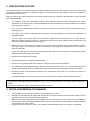
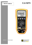
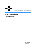
WARNING!
TEST POINT ADAPTER USE:
PLEASE VERIFY AND MAKE SURE THAT THE INSTALLATION OR THE CIRCUIT IS NOT POWERED WHILE YOU ARE
CONNECTING THE TEST POINT.
1
NO
CONDUCTIVE PART SHOULD REMAIN REACHABLE WHEN THE INSTALLATION IS SWITCHED BACK ON.
Connect the test probes to the installation or the electrical circuit only after making sure there is no current.
Connect the test probes to the installation or the electrical circuit only after they have been connected to the
corresponding measurement accessories, listed below:
ELECTRICAL SAFETY
CAT. II 300V
Code P01295458Z
2
11-0000-276 + P01295458Z: ELECTRICAL SAFETY CAT. II 300V
ELECTRICAL SAFETY
CAT. III 1000V
C d P01295288Z
CONDUCTIVE
PART
11-0000-276 + P01295288Z: ELECTRICAL SAFETY CAT. III
2
2. PRECAUTIONS FOR USE
This instrument and its accessories comply with safety standards IEC 61010-1, IEC 61010-031, and IEC 61010-2-032
for voltages of 600V in category III, or 1000V in category II, at an altitude of less than 2000m, indoors, with a degree of
pollution of not more than 2.
Failure to observe the safety instructions may result in electric shock, fire, explosion, and destruction of the instrument
and of the installations.
The operator and/or the responsible authority must carefully read and clearly understand the various
precautions to be taken in use. Sound knowledge and a keen awareness of electrical hazards are essential
when using this instrument.
If you use this instrument other than as specified, the protection it provides may be compromised, thereby
endangering you.
The safety of any system incorporating this instrument is the responsibility of the person who assembles the
integrated system.
For your safety, use only the cables and accessories supplied with the instrument: they comply with IEC
61010-031 (2002). When the sensors or accessories used are of a lower category than the instrument, the
lower rating must be applied to the entire system.
Before each use, make sure that the cables, junction boxes, and accessories are in perfect working condition.
Any cable, sensor, or accessory of which the insulation is damaged (even partially) must be set aside for
repair or eliminated.
Do not use mains power when making measurements. Mains power may be used only to recharge the internal
batteries, with the instrument switched off.
Respect the environmental conditions.
Use personal protection equipment systematically.
Never use it on systems of which the voltage or category is higher than that indicated.
For replacement of the internal battery, contact an authorised service centre only. These components have
specific safety devices; using non-original spare parts could cause serious damage to persons or property.
Respect the limits of the physical protections of the accessories and sensors. Do not place your hands on
unused terminals.
All troubleshooting and metrological checks must be performed by competent and accredited personnel.
• The maximum voltage between the inputs is 1000V DC . Do not measure voltage exceeding the limits in this manual.
• The maximum current the instrument tolerates is 10A DC . Do not carry out tests on FV module strings connected in
parallel.
• Never test FV modules or strings connected to the DC/AC converter.
3. NOTES CONCERNING THIS MANUAL
The information in this manual is subject to change without prior notice;
Although this manual has been written with the utmost care, please contact the manufacturer should you have
any comments, opinions or product-related questions;
Make sure you fully understand the pre-requisites for use of the product, such as its technical characteristics
and hardware and the software limitations affecting its use. We decline all responsibility for damage resulting
from improper use of the product;
Reproduction of this manual, in full or in part, without written permission from our company, is prohibited.
3
INDEX
1.
WARNINGS .......................................................................................................................................... 2
2.
PRECAUTIONS FOR USE .................................................................................................................. 3
3.
NOTES CONCERNING THIS MANUAL .............................................................................................. 3
4.
INTRODUCTION .................................................................................................................................. 5
5.
DESCRIPTION OF CONNECTIONS AND CONTROLS ..................................................................... 6
6.
DISPLAY UNIT ..................................................................................................................................... 7
7.
POWER SUPPLY................................................................................................................................. 7
7.1. Battery life ........................................................................................................................................ 7
7.2. Charging the batteries ...................................................................................................................... 7
7.3. Mains power supply unit .................................................................................................................. 7
8.
ON/OFF SWITCH................................................................................................................................. 7
9.
IMPORTANT NOTE FOR USE ............................................................................................................ 8
10. DESCRIPTION OF THE MENUS ........................................................................................................ 8
10.1. System ............................................................................................................................................. 8
10.2. Module Archive ................................................................................................................................ 9
10.3. Company Archive ........................................................................................................................... 10
10.4. Measurements Archive .................................................................................................................. 11
10.5. Installations Archive ....................................................................................................................... 11
10.6. USB ................................................................................................................................................ 12
USB-bluetooth adapter .......................................................................................................... 12
10.6.1.
USB pen drive ....................................................................................................................... 12
10.6.2.
11. MAKING MEASUREMENTS .............................................................................................................. 14
11.1. Electrical connections: ................................................................................................................... 14
11.2. Remote Unit ................................................................................................................................... 15
11.3. Module or String ............................................................................................................................. 15
11.4. Other functions ............................................................................................................................... 22
"FS" (full scale) function ........................................................................................................ 22
11.4.1.
Zoom Function ...................................................................................................................... 22
11.4.2.
12. TECHNICAL CHARACTERISTICS .................................................................................................... 24
12.1. Reference conditions ..................................................................................................................... 24
12.2. Specifications ................................................................................................................................. 24
12.3. Environmental conditions ............................................................................................................... 24
12.4. Construction specifications ............................................................................................................ 25
12.5. Electromagnetic compatibility ........................................................................................................ 25
12.6. Mechanical protection .................................................................................................................... 25
13. FTV200 PC SOFTWARE ...................................................................................................................... 26
13.1 General information ....................................................................................................................... 26
13.2 Installation ...................................................................................................................................... 26
13.3 Using the program ......................................................................................................................... 27
13. MAINTENANCE ................................................................................................................................. 36
13.1. Cleaning ......................................................................................................................................... 36
13.2. Metrological check ......................................................................................................................... 36
13.3. Repair............................................................................................................................................. 36
14.
WARRANTY ....................................................................................................................................... 37
15. TO ORDER ........................................................................................................................................ 38
15.1. Optional accessories ...................................................................................................................... 38
15.2. Spare parts .................................................................................................................................... 38
16.
LIST OF POP-UP DISPLAY MESSAGES ......................................................................................... 39
4
4. INTRODUCTION
The FTV200 I-V TRACER is a measuring instrument designed and built to meet the needs of technicians doing
troubleshooting or maintenance work on the photovoltaic generator or module in conformity to the IEC/EN 60891
standard.
Photovoltaic systems are in two main parts:
A photovoltaic generator comprising one or more strings of photovoltaic panels that generate a direct current.
An inverter that converts the direct current generated by the panel into alternating current so it can be used in the grid.
The FTV200 I-V TRACER has two measurement inputs, one for measuring voltage (V DC ) and one for measuring
current (I-DC). Measurements can be made on a single panel or on a string of panels (the latter measure is not
provided for in the standard).
There are also inputs for a pyranometer sensor and a temperature probe.
The temperature probe input accepts both the ambient temperature probe and the contact probe used to measure the
temperature of the photovoltaic panels.
All the electrical data measured in OPC operating conditions are “transferred” to radiation STC standard conditions
equal to 1000W/m2 and module temperature of 25°C applying the calculation formulas in conformity to the IEC/EN
60891standard.
The user may request the comparison (DPmax) between the maximum power (Pmax) stated by the manufacturer and
the maximum power measured during the test (OPC), transferred to the STC standard conditions (as stipulated in the
IEC/EN 60891 standard).
If the comparison value is within the manufacturer’s stated tolerance, the test result is "OK"; otherwise, it is "NO".
N.B.: the IEC/EN 60891 standard indicates the procedures for transferring the values measured under real OPC
operating conditions to the reference standard STC conditions for a single module. Consequently, a negative result for
a measurement test on one string of modules could mean that every single module has to be measured in order to
identify the defective module or modules in the string.
The FTV200 I-V TRACER instrument also lets you enter a percentage of "degradation" and the age (years) of the PV
module or of the PV string, further improving the accuracy of the test results.
To make the instrument easier to use in difficult conditions, an FTV100 REMOTE UNIT accessory is available to allow
wireless connection of the pyranometer sensor and the temperature probe; the sensor measurements are transmitted
to the instrument by BLUETOOTH, via a pair of adapters connected to the respective communication ports.
The main measurements made are:
⇒
measurement of solar radiation by pyranometer (up to 2000W/m²)
⇒
measurement of the ambient temperature or panel temperature by Pt100 sensor (up to 120°C)
⇒
possibility of measuring both single panels and strings of panels
⇒
measurement of the no-load voltage and the MPP voltage (up to 1000 V DC )
⇒
measurement of the short-circuit current and the MPP current (up to 10 A DC )
⇒
graphic representation of the I-V curve with marker at the MPP.
⇒
graphic representation of the power curve with marker at the MPP.
⇒
comparison of the measurements with the panel nameplate data and indication of the result:
OK/NO
⇒
calculation of the efficiency of the solar panels and display of the difference between the nominal value
and the measured value
⇒
measurement of the series resistance, Rs, in compliance with the requirements of standard EN60891
5
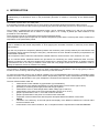
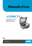
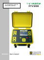
5. DESCRIPTION OF CONNECTIONS AND CONTROLS
5
6
1
2
3
7
4
8
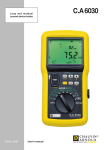
1)
2)
3)
4)
5)
6)
7)
8)
Temperature probe input
Pyranometer input
USB 2.0 port
External power supply input (15V DC; maximum current consumption 2A)
4.3" colour "touch-screen" LCD Monitor
Input for voltage measurements
Input for current measurements
Multi-function keypad including the following keys:
▲ : "up" arrow key
► :"right" arrow key
OK: button to confirm selection
◄ :"left" arrow key
▼ :"down" arrow key
On/off key
Return to main menu key
BATT Ch LED (active only with external power supply connected)
lit while battery is charging, which takes place ONLY when the instrument is Off
FULL CH LED INDICATOR (active only with external power supply connected)
lit when the internal batteries have reached full charge
6
6. DISPLAY UNIT
The FTV200 I-V TRACER has a 4.3" colour touch-screen LCD display that displays function access icons, menus, and
graphs of the I-V curves of the panel or string of panels measured.
Main screen
Graph Screen
7. POWER SUPPLY
7.1. Battery life
The battery icon in the lower right part of the display indicates the battery's charge status. The number of bars in the
icon is proportional to the charge level.
Battery fully charged. Remaining life approx. 12 hours
Battery semi-charged. Remaining life approx. 50 minutes
Battery low (blinking symbol). Remaining life approx. 10 minutes
7.2. Charging the batteries
The battery is charged with the INSTRUMENT OFF, using the power supply unit supplied with the instrument, which is
connected to the dedicated jack.
It is recommended that only the power supply unit provided with the instrument be used. This type of power supply unit
is specific to the instrument and ensures electrical safety.
If the battery is fully discharged, the charging time is approx. 5 hours.
7.3. Mains power supply unit
The mains power unit accepts voltages ranging from 90V to 260V-50Hz. The protecting fuses are inside the mains
power unit and are not accessible.
NOTE: If the fuses blow, do not replace them, but send the power supply unit to the service centre for inspection.
ATTENTION: use only the mains power unit to charge the internal batteries.
Before using the instrument to make measurements, make sure that the mains power unit is disconnected.
8. ON/OFF SWITCH
To switch the instrument On, press the
button and hold it down for approx. 3 seconds
NOTE: If, when the key is released after starting up, the instrument switches itself off, the batteries are not sufficiently
charged. Charge the batteries before use.
To switch the instrument Off, press the
button and hold it down for approx. 3 seconds
7
9. IMPORTANT NOTE FOR USE
To enter alphanumeric characters in one of the fields listed in the menus or in specific functions, use the keypad,
opened by touching the screen that corresponds to the desired field.
To switch the keypad from numeric to alphabetical mode, press the (ABC) key in the lower left corner.
To switch the keypad from alphabetical to numeric mode, press the (.?123) key in the lower left corner.
Keypad in numeric mode
Keypad in alphabetical mode
When it is impossible to use the TOUCH-SCREEN, the keypad on the front panel can be used to select icons and
control keys. Use the arrow keys to select the desired icon or control key, then confirm by pressing the OK key.
10.
DESCRIPTION OF THE MENUS
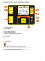
10.1.
System
If this icon is selected, a window containing the instructions and system settings opens as described below.
Before browsing this menu, please wait a few seconds until the Power Version Number is displayed.
Serial number: indication of the instrument's serial number.
SW Version: indication of the instrument's firmware version (upgradable through the "USB" menu)
Power Version: indicates the version of the instrument's measuring software.
Display: The date and time can be displayed at all times in the top bar of the display; pressing the
▼ key opens a
window in which you can select one of the following conditions:
Local: the date and time are not displayed.
Date-Time: the current date and time are displayed simultaneously.
Date: only the current date is displayed.
Time: only the current time is displayed.
Setting the date and time: the current date and time are displayed in their respective fields; to edit the date/time,
select the value to be changed using the ▲ or ▼ key.
Press the "Apply" button to confirm the new settings and exit from the menu.
Temperature probe: press the ▼ key to open probe type selection window:
Module: the measurements are made with allowance for the temperature of the photovoltaic module.
Ambient temperature: the measurements are made with allowance for the ambient temperature.
2
Sens. Pyra (mV/kW/m ): the pyranometer sensitivity value is displayed in the corresponding window. Because of a
-2
change of unit, this value is 1,000 times the value marked on the pyranometer (i.e. 0.01490mV/Wm x 1.000 =
2
14.90mV/kW/m ). If the assigned does not correspond to the pyranometer used or if the pyranometer is replaced,
select this window and enter a new value using the keypad displayed. Then press "Apply" followed by "Invio" ("Enter")
to confirm the new setting and close the function.
8
If the value set does not match that of the pyranometer being used, or if the pyranometer is replaced, select the
window on the screen, use the instrument's keypad to configure the new value, and when the change has been made
click on "ENTER" to confirm the setting and exit from the field.
Minimum radiation: can be used to set the minimum solar radiation value in W/m2, adjustable from 1 to 1,000W/m2,
used as reference by the instrument during a measurement.
Please always check that the value set is consistent with the measurement you want to make.
2
We recommend making measurements with a solar radiation value ≥700W/m in compliance with standard
IEC/EN60981.
Remote Unit: If the ▼ button is pressed, the remote unit activation window opens for selection of the type of
connection between the remote unit and the FTV200. Possible choices are:
Local, the probes are connected without the use of a remote unit.
RS-232 Serial Adapter, the BLUETOOTH module is connected to the instrument's USB port by an
RS232-USB adapter.
Bluetooth Adapter, the connection is via a USB-BLUETOOTH adapter module. When this item is selected, the
following two fields are activated for the following settings:
Bluetooth Address (MAC), if the corresponding field is selected, a keypad opens for entry of the "MAC" number of
the Bluetooth adapter used on the remote unit with which you want to communicate.
NOTE: For the Bluetooth devices of the instrument and the remote unit to be able to communicate, the MAC number
of the Bluetooth adapter used on the instrument must be set in the Bluetooth device used on the remote unit.
The PIN code setting of this device must not be activated.
To configure the device used on the remote unit, follow the instructions provided in the remote unit's manual.
Device name: this can be used to enter a name for the Bluetooth adapter used for the instrument; this is optional.
Brightness: click on the associated numeric value to modify it if necessary
Language: press the ▼ key to open the language selection window. Touch the desired language on the screen to
confirm the selection and exit.
Memory used: this displays the percentage of the instrument's memory occupied by the data entered and the stored
measurements.
Note that the available memory of the instrument is 84 MBytes.
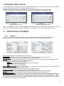
10.2.
Module Archive
Selecting this icon opens a window with the following functions:
New Module: Selecting this icon activates a function allowing entry of the model and plate data of a panel not present
in the pre-loaded list. If a new brand must be entered, exit by selecting "Exit", then select the "Edit Brand" icon.
Edit Brand: Selecting this icon opens a window containing a list of the brands present; select the "enter new brand"
line if you want to add a brand not present in the list. Select the window below the list to enter the new name, then
click on "SAVE" to confirm, or "Exit" to cancel the operation.
Working in the same way as described above, you can select and then edit the name of a brand already present.
Find: selecting this icon opens a window that lets you search the list of panels in memory according to a selection
criterion based on their electrical characteristics. Completing one or more of the fields for the main electrical
characteristics of the panels and pressing the "Search" button displays a list of panels matching the values entered.
This function can be used, for example, for a quick check of the brand and model of panels that have the selected
characteristics.
Edit Module: when this function is used – once the brand has been selected – it is possible to edit and update the
model and electrical characteristics of the listed panels
List: Selecting this icon opens a window displaying a list of the panels and their respective characteristics.
Delete: This function can be used to delete a brand from the list, or all panels that correspond to it, or a single panel.
To delete, select the brand and possibly the model; press "Delete Model" if you want to delete only the selected
model, "Delete Brand" to delete the brand and all of its contents.
Press the "Exit" button to return to the previous menu.
9
Module Archive menu window
New Module data entry window
The table below indicates ranges of values for the characteristic parameters of the panels that are entered when a
New Module record is created in the database.
Symbol
Measurement
unit
(W)
(V)
(V)
Description
P max
V mpp
V oc
Maximum power of the module
Voltage at maximum power point
No-load voltage
Type
Type of silicone in the cells
Beta
Toll –
NOCT
I mpp
I sc
Alpha
Gamma
Toll +
Voc temperature coefficient
Negative tolerance of P max stated by the PV module manufacturer
Nominal operating temperature of the cell
Current at maximum power point
Short-circuit current
I sc temperature coefficient
P max temperature coefficient
Positive tolerance of P max stated by the PV module manufacturer
10.3.
(%/°C)
(%)
(°C)
(A)
(A)
(%/°C)
(%°C)
(%)
Range
1.00 to 1000.0
1.00 to 200.0
1.00 to 200.0
Monocrystalline
Polycrystalline
Thin Film
Amorphous
Micromorph
-1.00 to -0.0001
0 to -50
0 to 100
0.2 to 10.00
0.2 to 10.00
-0.200 to + 0.200
-1.00 to -0.01
0 to +50
Company Archive
Select this icon to access the client record management, look-up, and deletion functions via the following menus:
New: select this icon to enter a new record. Click in the desired field to open the keypad; when you have finished
typing, confirm your entry by pressing "ENTER".
Note: the Tax code field must be filled in.
List: press this icon to open the list of all stored records; to view the details of a record, click on the corresponding line
and press "Open". To view the characteristics of the installations associated with the record, select the installations
and press "Display".
Edit: click on this icon to access the Edit record function; to make a change, select the desired record in the "Surname
- Company Name" field(s) and press the "Edit" button. Select the field to be edited, enter the changes, and confirm by
pressing "ENTER".
Delete: select this icon to open a list of stored records. Select the record you want to delete by highlighting it in the
"First name - Name" field and click on the "Delete" button to delete it from the memory.
Company Archive Windows
Menu Window Company Details Window
10
10.4.
Measurements Archive
Press this icon to access all measurement archive management windows. The available functions are:
Modules: click on this icon, then on "List", to display the records of all measurements made on individual panels.
Strings: click on this icon, then on "List", to display the records of all measurements made on strings.
To view the graph of a measurement, for both modules and strings, select the desired measurement in the list by
touching the desired item on the screen, then select the "Graph" button. When viewing the graph, you can use the
"FS" command in the top right corner to switch to full screen graph display mode or to display both the graph and the
command bar at the bottom of the screen, with the following items:
Module or String: displays the electrical data measured.
Environment: displays the ambient temperature and radiation measurements.
Power: displays the OPC or STC power curve on the graph, depending on the selection made.
Exit: return to previous menu.
Delete: click on this icon after selecting "Panels" or "Strings" to enter Delete measurement record mode. To delete a
record, select the desired line and press "Delete"
Measurements Archive Windows
10.5.
Installations Archive
Press this icon to access the installations archive in order to create, manage and if necessary delete measurement
records. The available functions are:
New: select this icon to enter the new installation entry window.
When the field of an item is selected, the data entry keypad opens; when you have finished entering the data, confirm
by pressing the "ENTER" key. Repeat the same steps for each field to be completed.
List: press this icon to open the list of all stored installations; to view the details of an installation, click on the
corresponding line, then press "Open". To view the data of a plant associated with the installation, select the plant and
press "Display".
Edit: click on this icon to access the Edit installation function; to make a change, select the desired installation in the
"ID" field and press the "Edit" button. A keypad opens when the field to be edited is selected; enter the changes, then
confirm by pressing "ENTER".
Delete: selecting this icon opens a window from which the list of stored installations is accessed. Select the installation
you want to delete, highlighting it in the "ID" field, then click on the "Delete" button.
Installation Archive Menu
Window Installation Data Entry Window
11
10.6.
USB
Select this icon to access the USB port management menu and its controls.
Main screen
USB menu screen
The USB port can be used to control the following devices.
10.6.1. USB-bluetooth adapter
this device allows the instrument to communicate with the "FTV100 Remote Unit" to obtain the measurements from
the atmospheric probes. The instructions for adjusting the USB-BLUETOOTH ADAPTER are given in Chapter 10.1,
"System".
10.6.2. USB pen drive
USB memory is used to transfer archives (measurements or settings) from the instrument to the PC and vice versa.
This is done by selecting the "Copy to…" or "Copy from…" command; a window then appears on the screen for the
selection of the destination folder or the "source" folder.
"Copy from..." message box
"Copy to..." message box
The "Copy to..." command corresponds to a transfer from the instrument onto the USB pen drive.
The "Copy from..." command corresponds to a transfer from the USB pen drive to the instrument.
The pen drive is also used to update the instrument's firmware. To carry out the update, make sure you have copied
the file with the "upg." extension to the USB key. Once the USB key connection is established, select "Update" in the
menu; a window in which to select the update file appears on the monitor. Select the file to be loaded, then click on
"Confirm". The progress bar displays the progress of the update; when it is complete, you are prompted to restart the
instrument. Press OK to finish the procedure.
File selection window
Update progress bar window
12
Restart command window
IMPORTANT NOTE: To ensure the correct operation of the USB devices, execute the following commands once the
USB key to be used has been inserted in the connector:
Connect: clicking on this command opens a window for confirmation of the connection between the instrument and
the device inserted in the port, USB-BLUETOOTH ADAPTER or USB PEN DRIVE. During the connection of the
inserted device, a connection progress indicator appears on the monitor.
Connection message box
Connection progress window
Disconnect: select this command to start the "safe" disconnection of the connected device.
The disconnection progress bar appears on the monitor; once disconnection is complete, it is possible to disconnect
the device in use from the connector.
Disconnection progress window
Disconnection complete message box
13
11.
MAKING MEASUREMENTS
Before making measurements, make sure that the pyranometer and the temperature probe have been connected, as
follows:
PYRANOMETER: the pyranometer must be placed on the same level as the modules to be tested; also make sure
that there are no shadows.
Attach the pyranometer directly to the PV module frame or to the main structure using the metallic accessory supplied
with the pyranometer (take care to avoid further shade by improper positioning of the pyranometer).
Make sure the angle between the sun’s ray and the module’s surface is as close as possible to 90°, the ideal angle for
obtaining excellent reliable results. If need be repeat the measurements at other times of the day.
Plug the connector directly into the instrument or the Remote Unit (if used).
AMBIENT TEMPERATURE PROBE: the temperature probe must be placed in a shaded area that is adequately
ventilated and near the modules.
Plug the connector directly into the instrument or the Remote Unit (if used).
PANEL TEMPERATURE PROBE: the temperature probe must be positioned on the back of the panel aligned to a
cell; if you are measuring a string of panels, place the probe on a panel in the middle of the string.
Plug the connector directly into the instrument or the Remote Unit (if used).
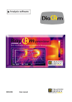
11.1.
Electrical connections:
The inputs for the V-DC voltage and I-DC current measurements are on the front panel.
Connect cables in parallel from the positive terminals of the instrument to the positive terminal of the panel or string
and from the negative terminals of the instrument to the negative terminal of the panel or string. This 4-wire connection
makes the voltage and current measurements of the panel or string independent and more accurate.
ATTENTION: use only the cables supplied for the electrical connections or, possibly, cables with suitable
characteristics and certifications.
If the measurement connection is made using cables other than those supplied, use cables that are as short
as possible.
Example of electrical connections without remote unit
Example of electrical connections with remote unit
14
11.2.
Remote Unit
The size of the plant may force you to place the instrument in a location far from the photovoltaic panels (for example,
an integrated plant on the roof with no possibility of making the electrical connections on the same level as the
modules or strings).
The FTV 100 remote unit (optional) can be installed next to the photovoltaic panels, thereby making it possible to
transmit the radiation, ambient temperature, and panel temperature measurements to the instrument in REAL TIME
(using the Bluetooth kit). This will make your testing very simple and accurate, and also let you view and store the
measurements.
How to make measurements using the remote unit:
-
Place the remote unit next to the panels.
Use the included RS232 cable to connect the module or environment temperature probe and the parallel
pyranometer to the Bluetooth adapter.
- Switch the remote unit ON (green LED ON). The green power LED of the Bluetooth adapter will light (if not,
set the selector on its side to "PoRI").
The remote unit now is ready to transmit measurements to the FTV200 I-V TRACER instrument.
How to program the FTV200 I-V TRACER instrument for use with the remote unit:
-
Turn the instrument On and open the "System" menu.
Choose the Remote Unit - Bluetooth Adapter option.
In the Bluetooth Address (MAC) option, enter the MAC number marked on the BLUETOOTH-RS232 adapter
connected to the remote unit.
- Click on "Apply" to confirm.
- Insert the USB-BLUETOOTH adapter into the USB port.
The instrument is now ready to receive measurements from the remote unit.
The LED on the USB-BLUETOOTH adapter will light only when measurements are activated from the "MODULE"
or "STRING" menu.
11.3.
Module or String
• The maximum voltage between the inputs is 1000VDC. Do not measure voltage exceeding the limits in this manual.
• The maximum current the instrument tolerates is 10A DC. Do not carry out tests on FV module strings connected in
parallel.
• Never test FV modules or strings connected to the DC/AC converter.
The measurement functions are as follows:
Module: to measure a single panel, select the "Module" icon in the main menu,
String: to measure a string of panels, select the "String" icon in the main menu,
Main menu
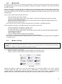
Selecting the Module or String icon in the main menu displays the connection diagram on the screen; pressing
"Continue" displays the graph. This is how the choice of measurement of a single panel or of a string of panels is
activated (the type of measurement selected is displayed at the top centre of the screen). Independently of the
selection made, the control buttons under the graph let you control the measurements as described below:
15
Start:
Pressing this button starts the measurement session; when the session is over, a graph showing the "I-V" curve in red
is created.
NOTE: Before the measurements are made, a test is run to verify the presence and correct operation of the ambient
or module temperature probe and the solar radiation (pyranometer) probe. If an error is found in the probe
measurements or the remote connection (if active), the measurement session is aborted. An error message appears
on the screen; check the connection and correct operation of the probe or the connection to the remote unit.
Single panel measurement window
Error message box
Error message box
Panel measurement graph
When "STRING" measurement is selected, a dialog box opens; the number of panels in the string to be tested must
be entered before the measurements are made.
String of panels measurement window
Number of panels entry window
16
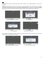
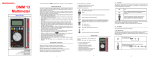
At the end of the test the instrument provides the characteristic I-V measured under real OPC conditions (red colour)
concerning the single module or string tested, as shown in the screen below
Characteristic I-V curve under real OPC conditions
The comparison between the I-V curve measured under real OPC conditions and that characteristic of the producer
under STC conditions (green colour) can be requested.
Using the command COMPARISON the MODULES ARCHIVE menu is displayed: select the brand and module model
tested to be used in the comparison.
When clicking on Valid the parameters inserted in the modules archive (corresponding to those stated by the producer
of the modules) are used and the values measured by the instrument under real OPC conditions are recorded to the
STC reference standard conditions.
Comparison:
Pressing this button opens a window for entry of the brand and model of the panel measured, in order to compare the
measurements with the nameplate data; the measured values will appear alongside the nominal characteristics of the
panel. For a more accurate comparison, the age and corresponding presumed percentage of panel performance
degradation are requested; if you do not want to enter these data, press the "Do not apply" button.
Reference panel selection window
Ageing values entry box
When the panel settings have been chosen, the results of the comparison are displayed in the bottom left corner of the
graph as follows:
Measurements @ STD – NO
For the case in which the verification of the manufacturer declared tolerance of maximum power % does not
fall within the range of values measured on the panel (or string).
Measurements @ STD – OK
For the case in which the verification of the manufacturer declared tolerance of maximum power % does not
fall within the range of values measured on the panel (or string).
17
Measurement graphs with comparison results
NOTE: the IEC/EN 60891 standard indicates the procedures for transferring the values measured under real OPC
conditions to the reference standard STC conditions for a single module. Consequently, a negative result for a
measurement test on one string of modules could mean that every single module has to be measured in order to
identify the defective module or modules in the string.
Measurements:
Press the "Measurements" button on the command bar below the graph to access the menu for the following
functions:
Rs: use this command to activate the Series Resistance measurement function.
The RS series resistance is one of the main features of PV modules and significantly influences their I-V
characteristics.
The series resistance is measured only on individual modules and, as stipulated in standard IEC/EN 60891, it is
measured in two stages, under different solar radiation conditions.
The first measurement must be made with a solar radiation value greater than 500W/mq. The second measurement
must be made with a solar radiation value that is at least 50 W/mq lower. The conditions necessary to ensure that the
measurements are correct are checked automatically by the instrument. The measurements made will later be saved
along with the measurements of the I-V curve in the panel tab, following the procedure described in the Save (bold)
section.
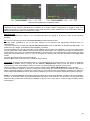
To make this measurement, proceed as follows:
When the Rs function is selected, two commands are proposed:
Calculation: pressing this button starts phase 1 of the measurements; a window opens on the monitor, highlighting
the measured radiation value Irr (W/m²) and the "Phase 1 Measurement" button. Press this button to make the
measurements. If the solar radiation value is not correct, a warning message appears on the screen.
When the phase 1 measurements have been made, a window with a "Phase 2 Measurement" button appears.
If the solar radiation condition is correct, pressing this button starts the second measurement session; otherwise, a
warning message appears on the screen. In this case you must wait until the solar radiation conditions are within the
proper range as described previously. When these conditions are correct, the second measurement phase can begin.
NOTE: To make the Phase 2 measurement without waiting for the natural atmospheric variation of the solar radiation,
a screen, for example a sheet of polycarbonate like those used in shop windows, can be placed over the panel being
tested and the pyranometer measuring the radiation to filter the sun's rays and so create the right conditions for the
measurement.
18
Below is a series of Rs measurement screens
Measured: clicking on the Measured button on the screen opens a window displaying the measurement made. The
window displays the Rs value and the two solar radiation test values.
Ambient measurements: Selecting this command displays the temperature and solar radiation measurements. The
Mod. Temp. and Amb. Temp. options are available for the reference. Indicates whether the measurements are being
made using the module temperature probe or the ambient temperature probe (previously selected).
The Remote Connection... message is present whenever the probes are connected via the remote unit.
Images of the Environment Measure Windows
19
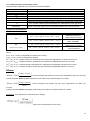
Module (or String):
Module (or String): on selecting one of these commands the "Electrical Data Measured" table is displayed (OPC
conditions and STC reference standard if comparison previously requested).
Electrical Data Measured window.
Power:
This command displays on the I-V curve graph of the panel or string the power curve (yellow colour) as well.
The window this command opens lets you choose between two options for the power curve to be displayed:
OPC: the instrument shows the trend for power output from the module/string under real OPC conditions
(calculated with the measured values).
STC: the instrument shows the trend for power output from the module/string under STC standard conditions
(calculated by transferring the values measured under STC standard conditions in compliance with IEC/EN
60891 standard).
NOTE: the STC selection button is present only when the brand and model of the comparison panel have been entered.
Representations of the OPC and STC power curves
Save: press the Save button to access the Saving module measurement function. The window that opens for this
function lets you enter a comment, which is saved in the measurements tab. Press the Save button in the dialog box to
save the measurements and the comment.
The saved measurements can be displayed using the "Measurements Archive" Menu, accessed from the main menu
(page 9 of the "MEASUREMENTS ARCHIVE" chapter).
Dialog box for saving the measurements
20
11.2.1 Interpreting the measurement results
The parameters measured by the instrument are described below
Parameter
P max
V mpp
I mpp
V oc
I sc
FF
DP max
DPmaxAvg
Description
Maximum Power of the PV module/string measured by the instrument
Voltage at maximum power point
Current at maximum power point
Open-Circuit Voltage
Short-Circuit Voltage
Fill Factor %
Difference between the maximum power measured by the instrument, referred to
STC, and the maximum power declared by the manufacturer, Pnom (@ STC)
Available only for measurements on strings: indicates the DPmax on only one
module. This value ought not to be considered reliable for the test’s purposes.
Result of the measurements
Result
Conditions
Tol
Note
* P nom ≤ (P max - P nom ) ≤ Tol
(+)
* P nom
DEGRADATION NOT
TAKEN INTO ACCOUNT
* P nom1 ≤ (P max - P nom1 ) ≤ Tol
(+)
* P nom1
DEGRADATION TAKEN
INTO ACCOUNT
* P nom ≤ (P max - P nom ) ≤ Tol
(+)
* P nom
(-)
OK
Tol
Tol
NO
(requirements not satisfied)
(-)
Tol
(-)
(-)
* P nom1 ≤ (P max - P nom1 ) ≤ Tol
(+)
* P nom1
DEGRADATION NOT
TAKEN INTO ACCOUNT
DEGRADATION TAKEN
INTO ACCOUNT
Where:
P max - P nom ) DP max (degradation not taken into account)
(P max - P nom1 ) DP max (degradation applied)
Tol
(-)
(%) * P nom = Negative tolerance declared by the manufacturer (degradation not taken into account)
Tol
(-)
(%) * P nom1 = Negative tolerance declared by the manufacturer (degradation taken into account)
Tol
(+)
(%) * P nom = Positive tolerance declared by the manufacturer (degradation not taken into account)
Tol
(+)
(%) * P nom1 = Positive tolerance declared by the manufacturer (degradation taken into account)
DPmax:
P max − Pnom1
Control parameter that defines the test result (degradation taken into account)
DP max = 100 *
Pnom1
Control parameter with degradation (defines the test result for the measurements on module)
P max − Pnom
DP max = 100 *
Pnom
Control parameter that defines the test result (degradation not taken into
account)
Control parameter without degradation (defines the test result for the measurements on module)
DPmaxAvg: (only displayed for measurements on strings)
Control parameter that defining the test result for the measurements on the string
21
Fill Factor:
FF = 100 * [(V mpp * I mpp )/(V oc * I sc )]
This indicates the presumed efficiency of the PV module/string
as determined by the ratio of the maximum measured power
to the product of the short-circuit current and the open-circuit voltage.
KEY:
P nom1 = P nom * (1 - Deg * Age) = PV module nominal power calculated with degradation (if taken into account)
P nom = PV module nominal power (@ STC)
Deg. = Degradation (%)
Age = PV module age (years)
If Deg = 0 or Age = 0 then P nom1 = P nom
11.4.
Other functions
11.4.1. "FS" (full scale) function
When the graphs are displayed, use the FS button in the upper right of the monitor to switch to full-screen mode.
The increased height of the graph gives a better view.
To return to the normal viewing mode, press the FS button again.
Full-screen view
11.4.2. Zoom Function
The zoom function can be used to enlarge a portion of the graph and allow a more detailed analysis of a given part
the curve shown.
To use the zoom function, touch the screen with the stylus and drag to highlight the portion of the graph you want
enlarge. During this operation, a white rectangle is drawn on the screen to help you define the area you want
enlarge.
When the stylus is removed from the screen, the zoom mode is automatically activated and the area defined
displayed in full-screen mode.
In the top right corner of the screen, above the Full Screen (FS) function button, there are two command buttons
control the zoom function. These buttons are:
of
to
to
is
to
22
In: each time this button is pressed, the magnification increases.
Out: each time this button is pressed, the magnification decreases, until the "normal" display is restored.
STC-Ok
STC-Ok
23
12.
TECHNICAL CHARACTERISTICS
12.1.
Reference conditions
Influence quantities
Reference values
Temperature
20 ± 3 °C
Relative humidity
45 to 55 % RH
Supply voltage
Internal battery
Electric field
< 1 V/m
Magnetic field
< 40 A/m
12.2.
Specifications
4.3" COLOUR GRAPHIC LCD WITH BACKLIGHT AND TOUCH-SCREEN
RESOLUTION 480 x 272 BRIGHTNESS 500 cd/mq CONTRAST 400:1
DISPLAY
MEASUREMENTS
METHOD
RANGE
ACCURACY
RESOLUTION
THERMOPILE
PYRANOMETER
from 0 to 2000W/m
<3%
1W/m
AMBIENT TEMP.
PT100 PROBE
-20 to +100°C
< 2% ± 1°C
0.1°C
MODULE TEMP.
PT100 PROBE
-20 to +100°C
< 2% ± 1°C
0.1°C
VOLTAGE
DC VOLTMETER
10 to 1000 V;
± 1%
0.1 V
CURRENT
DC AMMETER
0.1 to 10 A;
± 1%
0.01 A
POWER
I-V MEASUREMENT
10 W to 10 KW
± 1%
0.1 W
SERIES
RESISTANCE
I-V MEASUREMENT
0.1 Ω to 100 Ω
< 2% ± 0.1 Ω
0.01 Ω
SOLAR RADIATION
2
2
I-V GRAPH
I-V CURVE OF THE PANEL or STRING OF PANELS
MPP GRAPH
POWER CURVE WITH MARKER ON MPP POINT
DATA LOGGER
RECORD STORAGE INCLUDING: CLIENT DETAILS, PLANT CHARACTERISTICS,
GRAPHS. INTERNAL MEMORY CAPACITY 80 MB FOR A TOTAL OF 10,000
RECORDS.
POSSIBILITY OF USING "USB" EXTERNAL MEMORIES
COMMUNICATION
PORT
USB 2.0
INTERNAL POWER
Li-Ion BATTERY PACK, 16V 4.5Ah
MAX CONSUMPTION IN USE 0.6A
MAINS POWER
SUPPLY
EXTERNAL POWER SUPPLY 220-V AC 50Hz with 3-pole mains cord and SHUKO plug
OUTPUT 16V 3.8A DC MAX CONSUMPTION IN BATTERY CHARGE MODE 2A
12.3.
Environmental conditions
Use indoors or outdoors.
Range of use
Storage (without battery)
Degree of pollution:
Altitude
- 5 to +40 °C
- 10 to +60 °C
2
< 2000 m
80 % RH max.
80 % RH max.
24
12.4.
Construction specifications
Dimensions of the instrument (L x W x H): 270 x 250 x 130 mm
Weight: approximately 2.5 kg (battery included)
12.5.
Electromagnetic compatibility
Emissions and immunity in an industrial setting compliant with IEC 61326-1.
12.6.
Mechanical protection
IP 54 per IEC 60529 (with lid closed)
IK 04 per IEC 50102
25
13. FTV200 PC SOFTWARE
13.1 General information
The FTV200 PC SOFTWARE is an application package installed on the PC to let you manage the same archives as
are present on the instrument.
This application can be used to import the records of the measurements and their respective graphs so they can be
printed or used according to the user's requirements.
In addition, it is possible to prepare the "Installation" records and the "Company" records, edit or update the Database
of modules, then transfer the new data to the instrument.
13.2 Installation
The software is automatically installed when the CD supplied is inserted.
If your PC is not set up to start the CD automatically, click on My Computer in the Start menu, then right-click on "CD
ROM Unit" and select Open by left-clicking; this opens the window displaying the contents of the CD.
Double-click on the "FTV200_SETUP icon to start the installation.
Language selection is prompted first. Select the desired language and press OK to continue.
Follow the instructions that appear on screen until the installation procedure is complete; the program icon will then be
available on the desktop.
Desktop Icon
26
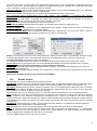
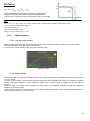
13.3 Using the program
When the program is started, the main window appears as shown below.
The command bar in the upper left part of the window includes buttons for the following functions:
PV modules: press this button to access the archive where the Brand and Module folders are stored.
Selecting the Brand folder lets you enter a new brand, edit a brand in the list, or delete a module brand and all models
associated with it.
When you select the module folder, you can enter, edit, and delete data for a selected single panel.
Press close to return to the main menu.
27
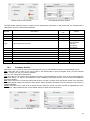
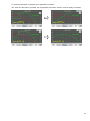
Meas.: if this button is pressed the measurements archive folder opens as shown in the following image.
This window displays a list of stored measurements; select a measurement on the right to display the "Electrical Data
Measured", the "Ambient Measurements" recorded when the electrical measurements were made, and the results of
the comparison between the measurements made and the standard characteristics of the module (or string).
The commands located under "Curve Selection" let you select the curves you want to display by checking the
corresponding box(es).
After making your selection, press the "Graph" button on the screen to open the graph window.
Right-click with the mouse on the desired area of the graph; a menu pops up to let you print the graph or perform other
authorized operations.
Chart: press this button to view the electrical measurement data and corresponding graph.
The "Export" button let you export the data in PDF format.
Export: clicking on this button saves the selected measurement and corresponding graph in Excel format. Follow the
PC's operating system instructions to finish saving the file.
28
Delete: the "Delete" command eliminates the selected measurement from the list. When this button is pressed, a dialog
box opens on the monitor and asks you to confirm (YES button) or cancel (NO button) the deletion.
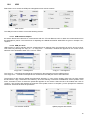
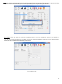
PV. Install.: press this button to access the installations tab; a list of the installations stored in the database is
displayed.
The right side of the tab displays the complete record of the selected installation; below this, in the "Measurements"
section, is a list of measurements belonging to the record.
The Installations tab
29
The commands below the installations list let you perform the following operations:
New: this command is used to enter a new installation and corresponding record in the archive. When the button is
pressed, the fields are cleared and can be completed. When you have finished, click on OK to save the new record or
Cancel to exit without saving.
Modify: this command is used to edit the record of the selected tab.
When the button is pressed, the record fields are made available so the desired changes can be made.
Mouse-click in the field to be edited and type the changes.
When finished, press the OK button to save the changes, or Cancel to exit from the edit function without saving.
30
Delete: use this command after selecting a specific installation from the list in order to delete it from the database.
When the button is pressed, a dialog box opens and prompts you to confirm or cancel the operation.
Select YES to delete the installation or NO to cancel the operation.
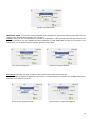
Companies: press this button to access the companies tab, which displays a list of the companies stored in the
database.
The right side of the tab displays the complete record of the selected company; below this, in the "Installations"
section, is a list of the installations belonging to this record.
The Companies tab
31
The command buttons below the list of companies let you perform the following operations:
New: this command is used to enter a new company and corresponding record in the archive. When the button is
pressed the fields are cleared and can be completed. When you have finished, click on OK to save the new record or
Cancel to exit without saving.
Modify: this command is used to edit the record of the selected company.
Clicking on the command makes the record fields available for the desired changes to be made.
Mouse-click in the field to be edited and type the changes.
When finished, press the OK button to save the changes, or Cancel to exit from the edit function without saving.
32
Delete: use this command after selecting a specific company in the list, in order to delete it from the database. When
the button is pressed, a dialog box opens and prompts you to confirm or cancel the operation.
Select YES to delete the installation or NO to cancel the operation.
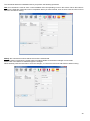
Import/Export: this function is used to manage the transfer of the entire database, or part of it, from the PC to a pen
drive or vice versa.
This procedure can be used to transfer the new settings of the various tabs from the PC to the instrument. The same
procedure is used to transfer the measurement archives from the instrument to the PC.
When the function button is pressed, the window shown below opens.
The tab shows 5 database sections: Module measurements, String measurements, Modules, Installations,
Companies. Next to each section is a check box which lets you choose the part of the database you want to manage;
a check indicates that the corresponding item has been activated.
33
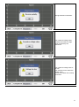
The database management commands are:
Import: this command opens a dialog box in which you can select the path of the folder to be imported. See the
example in the figure below.
When you have selected the folder to be imported, click on Open. To finish the procedure, follow the instructions
provided on screen.
Export: selecting this command opens a dialog box in which you can select the path of the folder to be exported. See
the example in the figure below.
Select the destination and click on Save. To finish the procedure, follow the instructions provided on screen.
34
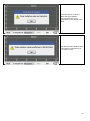
Remove: this command lets you delete selected items in the database.
Clicking on the command opens a Confirm cancellation window.
Click on YES to confirm or NO to cancel.
35
13.
Maintenance
The instrument contains no parts that can be replaced by personnel who have not been specially
trained and accredited. Any unauthorized repair or replacement of a part by an "equivalent" may gravely
impair safety.
13.1.
Cleaning
Disconnect the unit completely and turn the instrument OFF.
Use a soft cloth, dampened with soapy water. Rinse with a damp cloth and dry rapidly with a dry cloth or forced air. Do
not use alcohol, solvents, or hydrocarbons.
13.2.
Metrological check
Like all measuring or testing devices, the instrument must be checked regularly.
This instrument should be checked at least once a year. For checking and calibration, contact one of our accredited
metrology laboratories (information and contact details available on request), at our Chauvin Arnoux subsidiary or the
branch in your country.
13.3.
Repair
For all repairs before or after expiry of warranty, please return the device to your distributor.
36
14.
WARRANTY
Except as otherwise stated, our warranty is valid for twelve months starting from the date on which the equipment
was sold. Extract from our General Conditions of Sale provided on request.
The warranty does not apply in the following cases:
• Inappropriate use of the equipment or use with incompatible equipment;
• Modifications made to the equipment without the explicit permission of the manufacturer’s technical staff;
• Work done on the device by a person not approved by the manufacturer;
• Adaptation to a particular application not anticipated in the definition of the equipment or not indicated in the
user’s manual;
• Damage caused by shocks, falls, or floods.
37
15.
TO ORDER
FTV 200 I-V TRACER ................................................................................................................................. P01160740
The instrument is supplied in a hard carrying case:
3m cable set (R/N) with MC4 compatible connectors
1 magnetic touch-screen stylus
1 set of 2 flexible test probes (1R/1N), to be used only with the cables supplied
1 pyranometer for solar radiation + 5m connection cable
1 Pt100 ambient temperature probe, 3m
1 Li-Ion battery + mains power unit
Data transfer software and user manual in USB key
Certificate of conformity
Carrying case for accessories
Instruction manual in Italian
FTV 200 I-V TRACE ................................................................................................................................. P01160745
The instrument is supplied in a hard carrying case:
3m cable set (R/N) with MC4 compatible connectors
1 magnetic touch-screen stylus
1 set of 2 test probes (1R/1N) Flex, to be used only with the cables supplied
1 Li-Ion battery + mains power unit
Data transfer software and user manual in USB key
Certificate of conformity
Carrying case for accessories
Instruction manual in Italian
15.1.
Optional accessories
FTV100 remote unit + 2 male/male RS232 connectors.............................................................................. P01160736
Bluetooth communication kit (transmitter/receiver – already programmed) ............................................. P01160739
1 Pt100 probe for panel temperature .......................................................................................................... P01160732
15.2.
Spare parts
1 pyranometer for solar radiation + connection cable ................................................................................. P01160730
1 Pt100 probe for ambient temperature ...................................................................................................... P01160731
1 Pt100 probe for panel temperature .......................................................................................................... P01160732
Li-Ion battery, 14.8V 4.5Ah ......................................................................................................................... P01160735
Magnetic stylus ........................................................................................................................................... X02934A00
Carrying case for accessories..................................................................................................................... P01298066
38
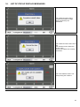
16.
LIST OF POP-UP DISPLAY MESSAGES
The measured current value
exceeds the maximum range
value supported by the
instrument.
The measured current value is too
low.
The instrument can’t detect the
current value.
Check if the cables are correctly
connected.
The solar radiation value is not
steady during the measure.
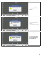
39
The measured energy value
exceeds the maximum range
value supported by the
instrument.
One or more cables are not
connected.
Check the electrical connections.
The measured power value
exceeds the maximum range
value supported by the
instrument.
40
Wrong electrical connections.
The measured voltage value
exceeds the maximum range
value supported by the
instrument.
The measured voltage value is
too low.
The instrument can’t detect the
voltage value.
Check if the cables are correctly
connected.
41
Communication error during the
measure.
Possible causes: internal
instrument failure or wrong
instrument update procedure.
Turn off and then turn on
instrument.
If the problem persists please
contact our after sales service.
Communication error during the
measure.
The instrument tried to reset the
internal part of the instrument
unsuccessfully.
Turn off and then turn on the
instrument.
If the problem persists please
contact our after sales service.
The instrument’s internal
temperature is too high. Wait for
the cooling before perform other
tests.
42
The calculation of the equivalent
ETC photovoltaic cell temperature
compliant the standard CEI EN
60904-5 is over limit.
The remote unit not connected or
turned off.
The instrument is not able to
detect the temperature of the
probe.
Check the insertion of the
temperature probe.
43
The instrument is not able to
detect the solar radiation.
Check the insertion of the
pyranometer or any shade of the
same.
The detected solar radiation value
is less than the minimum set in
the “system” menu.
44
45
11 – 2013
Code 693873C02 – Ed.1
DEUTSCHLAND - Chauvin Arnoux GmbH
Strasburger Str. 34 - 77694 Kehl / Rhein
Tel: (07851) 99 26-0 - Fax: (07851) 99 26-60
SCHWEIZ – Chauvin Arnoux AG
Einsiedlerstraße 535 - 8810 Horgen
Tel: 044 727 75 55 - Fax: 044 727 75 56
ESPAÑA - Chauvin Arnoux Ibérica S.A.
C/ Roger de Flor N° 293, Planta 1- 08025 Barcelona
Tel: 902 20 22 26 - Fax: 934 591 443
UNITED KINGDOM – Chauvin Arnoux Ltd
Waldeck House - Waldeck Road - Maidenhead SL6 8BR
Tel: 01628 788 888 - Fax: 01628 628 099
ITALIA - AMRA SpA
Via Sant’Ambrogio, 23/25 - 20846 Macherio (MB)
Tel: 039 245 75 45 - Fax: 039 481 561
MIDDLE EAST – Chauvin Arnoux Middle Est
P.O. BOX 60-154 - 1241 2020 JAL EL DIB (Beirut) - LEBANON
Tel: (01) 89 04 25 - Fax: (01) 89 04 24
ÖSTERREICH - Chauvin Arnoux Ges.m.b.H
Slamastrasse 29 / 2 / 4 - 1230 Wien
Tel: 01 61 61 961-0 - Fax: 01 61 61 961-61
CHINA – Shangai Pu-Jiang – Enerdis Instruments Co.Ltd
3 F, 3 rd Building - N° 381 Xiang De Road - 200081 SHANGHAI
Tel: +86 21 65 21 51 96 - Fax: +86 21 65 21 61 07
SCANDINAVIA - CA Mätsystem AB
Box 4501 - SE 18304 TÄBY
Tel: +46 8 50 52 68 00 - Fax: +46 8 50 52 68 10
USA - Chauvin Arnoux Inc - d.b.a AEMC Instruments
200 Foxborough Blvd. - Foxborough - MA 02035
Tel: (508) 698-2115 - Fax: (508) 698-2118
http://www.chauvin-arnoux.com
190, rue Championnet - 75876 PARIS Cedex 18 - FRANCE
Tel.: +33 1 44 85 44 85 - Fax: +33 1 46 27 73 89 - [email protected]
Export: Tel.: +33 1 44 85 44 86 - Fax: +33 1 46 27 95 59 - [email protected]
46