1
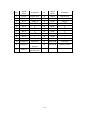
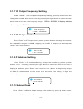
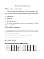
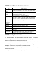
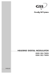
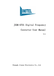
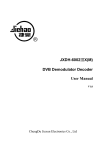
JXDH-6302 QAM Modulator
User Manual
V1.5
Chengdu
Jiexun Electronics Co.,Ltd
INITEL
TELECOMMUNICATIONS
JXDH-6302 QAM Modulator User Manual v1.5
Chengdu Jiexun Electronics Co., Ltd
Charter One Outline
1.1 Outline
The manual describes the shell, assembly, functions, installation, and all the
standard options which receivable of this QAM Modulator, including as follows:
Summarize
Installation
Operation
1.2 Digital TV brief introduction
Digital TV is defined as provide satellite TV transmission and digital TV
programs services by means of digital transmitting, thereby provide users high quality
images and features services in the integrated digital TV channels services.
Digital TV system consists of three parts: digital TV head end systems
transmit networks, user end system. As bellow chart1:
Transmit network
Digital Content
Storage,directory,
Sink
decompression
decode
decrypt CA
MPEG compression,
encode, encryption, etc.
Disposal
warrant
Searching content
Broadcast outlet
Return path
(HFC PSTN ISDN
Interact
Edit software
Operating system
Output signal
Digital TV is the necessary result of digital technology in the filed of development
for TV. Digital TV is make analog signals to digital signals by sampling, quantify and
encoding. Television system should include content, transmission and reception.
The content is collection, make etc. Transmission is delivery the content to terminal
1/19
Http:// WWW.JIE-XUN.COM
E-mail jx @j ie-xun.com
JXDH-6302 QAM Modulator User Manual v1.5
Chengdu Jiexun Electronics Co., Ltd
end via satellite, territory, cable network etc., thereby to composing a integrity
digital TV system . The network for transmission digital system can be satellite,
CATV, territory transmitting, and ADSL. In addition, The user end feedback the
user ’s interactive information to the digital TV head end system via the return path,
the return path can be composed of network as HFC route, W ireless Return Path,
PSIN, ISDN.
User end is what we called set top box(STB),User receive digital TV business
information via STB, and shows them on the end equipments. Digital head end
system can be divided to signal source processing, information processing and
transmission processing three parts. For example various head programs, encoding
equipments be part of signal source processing, program multiplex, scrambling etc.
be part of information processing, QAM modulator, missed signals be part of
transmission processing. It can be divided to user administer system, CA subsystem ,
DVB-C front end equipment subsystem, store and edit digital programs subsystem ,
digital broadcasting and middle subsystem etc., as following chart:
Signal sources
Transmission process
Signal processing
QAM Modulator
Program
Multiplex,
Scrambling
NVOD
Satellite Programs
SDH program down
local program,
Other program sources
Program database
Application
software
CA sys
Local
interact
business
Content
admin
Mixer
EPG
edit
User admi sym
Return signal
Call center
User request
Broadcast
control admin
2/19
Http:// WWW.JIE-XUN.COM
E-mail jx @j ie-xun.com
JXDH-6302 QAM Modulator User Manual v1.5
Chengdu Jiexun Electronics Co., Ltd
Terminology
CA: Condition Access;
DVB-C: Digital Video Broadcasting-Cable;
MMDS: Multichannel Microwave Distribution System;
DSL: Digital Subscriber Line;
HFC: High-Frequency Current;
PSTN: Public Switched Telephone Network;
ISDN: Integrated Services Digital Network;
DVS: Digital Video System;
DTX: Digital TV Exchange platform;
QAM: Quadratur e Amplitude Modulation;
STB: Set Top Box;
EPG: Electronic Program Guide;
MPEG: Moving Picture Express Group;
DVB: Digital Video Broadcasting;
PSI: Program Specific Information;
SI: Service Information;
ASI: Asynchronous Serial Int erf ace.
3/19
Http:// WWW.JIE-XUN.COM
E-mail jx @j ie-xun.com
JXDH-6302 QAM Modulator User Manual v1.5
Chengdu Jiexun Electronics Co., Ltd
Charter 2 Product Summarize
2.1 Summarize
In the broadcasting process of digital TV programs, QAM modulator mainly complete QAM
modulate and up-frequency conversation process for TS stream, Apply to multi-level transmission,
broadcasting of digital TV business.
QAM modulator mainly used in head end of digital TV broadcasting, it is composed by t wo
modules QAM modulator and digital up-frequency conversation, modulate the input serial or
parallel TS str eam via the QAM modulator module, modulate to IF frequency, then pass the
up-frequency conversation module to frequency transform, into standard channel or supplem ent
channel which meet demand. Finally mixed enter into CATV network, and received by the terminal
STB.
2.2 System components and working principle
2.2.1 System components
QAM Modulator components as below:
SPI
ASI
DS3
E3
DP
QAM
Process
IF output
35.25/36/36.15/44M
H
RF output
RF
48
860MHz
modulate
IF
process
CPU
Network Control Interface
LED
Keyboard
LCD
Chart 2-1 QAM digital modulator components
4/19
Http:// WWW.JIE-XUN.COM
E-mail jx @j ie-xun.com
JXDH-6302 QAM Modulator User Manual v1.5
Chengdu Jiexun Electronics Co., Ltd
QAM modulator mainly composed by following modules:
Data processing cell transform the input signals from all sorts of interfaces to standard
signals and make necessary data processing, make the pretreatment of QAM
modulate.
QAM modulate cell modulates the data stream to spectrum signal, IF modulates output
as 35.000-44.00MHz (stepping as 125KHz) adjustable.
RF modulate cell transform the IF to 110-862 MHz to TV channels.
CPU/LCD/LED/keyboard units complete keyboard input, LED display and smart control
etc.
2.2.2 Principle
JXDH-6302 QAM Modulator comply with DVB-C standard(GY/T 170-2001
INMOD-6302
GY/T
106-1999),Digital signal will multi-process together with other data stream via MPEG-II
compress and encode, the send to QAM modulator, QAM encode is according to DVB
technical criterion, such as interweave, RS error correcting encode etc.. After processed by
IF then up-frequency conversation to TV channels , so that to broadcast in HFC, microwave
MMDS network, can be applied in digital TV, digital broadcasting, video-on-demand, internet,
video conference and so on digital broadband application system.
2.3 Features
Support IYU-T.83A
Error correct encode completely meet DVB-C standard
Be workable under QPSK, 16QAM, 32QAM, 64QAM, 128QAM, 256QAM mode
Input interface: ASI and SPI (DS3/E3 optional)
Input date bit rate range: 1.5 51.6Mbps
Output data bit rate range: 2 56Mbps
Output signal Bandwidth(BW) range: 1.15 8.05MHz(roll down coefficient is 0.15)
Output data symbol rate range: 1
7Mbaud/s
5/19
Http:// WWW.JIE-XUN.COM
E-mail jx @j ie-xun.com
JXDH-6302 QAM Modulator User Manual v1.5
Chengdu Jiexun Electronics Co., Ltd
RF frequency range: 110 862MHz
Output level range: 95dBuV 115dBuV (stepping -0.5dB/step adjustable )
188/204 packet length adaptable itself
Adopt big enough cache design, ASI interface support paroxysmal and symmetrical input
TS stream, and can equilibrate and reforming the TS stream, enhance the efficiency of output
TS stream.
Input data empty packet filtering and output data fill in.
PRC proofread function, can accurately correct several PCR of input data separately.
Real time inspect and display for the efficient TS stream.
Adaptable itself to filtering circuit design to ensure the excellent suppress capability out of
band.
-20dB RF test mouth to monitor IF output.
Fault alarm display
LCD screen display
Network control interface, make centralize management, remote upgrade and maintenance
(network management software only for option)
Power-off memory
2.4 Data Interface
2.4.1 ASI interface (Asynchronous Serial Interface)
A. Input
Socket: BNC
Impedance: 75
Packet format: 188 or 204 byte(no route encode)
Route data speed velocity: 270Mbps
Max efficient data: 51.6Mbps
Standard: meet DVB standard, support paroxysmal and symmetrical input TS stream.
B. Ring route output
6/19
Http:// WWW.JIE-XUN.COM
E-mail jx @j ie-xun.com
JXDH-6302 QAM Modulator User Manual v1.5
Chengdu Jiexun Electronics Co., Ltd
Socket: BNC
Impedance: 75
2.4.2 SPI Input Interface (Synchronous Parallel Interface)
Socket: DB-25 female
Packet format: 188 or 204 byte(no route encode)
Standard: compatible of DVB, LVDS working methods.
2.5 IF Interface
A. IF output
Linker: BNC socket
Impedance: 75
Center frequency: 35.000 44.000MHz adjustable (stepping 125KHz)
IF bandwidth: 8MHz
Return loss: 18dB
Input level: 100dBuV
2.6 RF Interface
A. RF output
Connector: F jack (the metric system)
Impedance: 75
Output frequency: 110MHz
862MHz (provide per model)
Return loss: 12dB
Output level: Max 115dBuV(adjustable, stepping at 0.5dB)
Level adjustable range: 0 20dB
Carrier suppression: >55dB
Modulate error rate(MER): 32dB(closing balance), 45dB(opening balance)
Bit modulate error rate(BER):
1*10-8
SNR(Outside band): 50dB
7/19
Http:// WWW.JIE-XUN.COM
E-mail jx @j ie-xun.com
JXDH-6302 QAM Modulator User Manual v1.5
Chengdu Jiexun Electronics Co., Ltd
B. RF test output
Connector: BNC
Impedance: 75
Output level: 75dBuV 95dBuV (adjustable)
2.7 Signal channel coding
Modulate mode: 16QAM
32QAM
64QAM
128QAM
256QAM
Channel coding: comply with DVB standard RS coding
IF modulate error rate(MER): 44dB
SNR(outside band): 50dB
2.8 Network administration interface
Ethernet interface: Ethernet IEEE802.3, RJ45interface
Software agreement the SNMP agreement
2.9 power supply
Voltage: 100-240VAC
Frequency: 50Hz 2%
Electric Power: 20W
2.10 Working environment
Surrounding temperature:
Storage temperature:
25 C
5C
45 C
+55 C
Relative humidity: 10 75%
2.11 Radiate and safety requirements
Comply with GB13837-92 and GB8898-88 standard.
8/19
Http:// WWW.JIE-XUN.COM
E-mail jx @j ie-xun.com
JXDH-6302 QAM Modulator User Manual v1.5
Chengdu Jiexun Electronics Co., Ltd
2.12 Dimension
44.5mm
height 1U
×483mm(width,19 ) ×300mm(deep)
2.13 Weight
3.5 kg
2.14 Figure and description
Front panel sketch:
JXDH-6302 QAM Modulator
INMOD-6302
Power
Enter Menu
Digital
Video
Broadcasting
Alarm
1
2
3
4
1.
LCD screen display
2.
Power supply indicator
3.
Fault alarm indicator
4.
UP/DOW N/LEFT/RIGHT button
5.
Confirm Button
6.
Menu/Cancel button
5
6
Rear panel sketch:
Ethernet
ASI
IF OUT
OUT
RF OUT
TEST
AC110V-220V-50/60Hz
IN
2.14.1 SPI input interface:
9/19
Http:// WWW.JIE-XUN.COM
E-mail jx @j ie-xun.com
JXDH-6302 QAM Modulator User Manual v1.5
No.
Signal
name
Chengdu Jiexun Electronics Co., Ltd
description
No.
Signal
name
description
1
CLK-A
Signal clock
14
CLK-B
Signal clock
2
GND
grounding
15
GND
Grounding
3
D7-A
Data 7th
16
D7-B
Data 7th
4
D6-A
6th
17
D6-B
6th
5
D5-A
5th
18
D5-B
5th
6
D4-A
4th
19
D4-B
4th
7
D3-A
3rd
20
D3-B
3rd
8
D2-A
2nd
21
D2-B
2nd
9
D1-A
1st
22
D1-B
1st
10
D0-A
0
23
D0-B
0
11
DVALID-A
Data valid
24
DVALID-B
Data valid
12
PSYNC-A
25
PSYNC-B
Packet synchro
13
Cable
Packet
synchro
Cable
shielding line
10/19
Http:// WWW.JIE-XUN.COM
E-mail jx @j ie-xun.com
JXDH-6302 QAM Modulator User Manual v1.5
Chengdu Jiexun Electronics Co., Ltd
Charter 3 Operation
QAM m odulator front panel is for user operate, before normal operation you
can keep the default setting witch is the factory setting, and you can setting for
input, output parameter, operation. Input setting including selecting input interface,
setting output parameter.
3.1 Setting operation
3.1.1 Boot interface
After boot it, the LCD displays as below:
JX-QAM
RF: 470.000MHz
IN
SR: 6875K/S 64QAM
Here pressing RIGHT button, the screen displays as below :
Avai Rate: 00.000Mbps
In Rate: 00.000Mbps
It is for inspect the input code rate timely, press “Menu” for quit.
3.1.2 Main menu setting:
Click on “Menu” enter m ain menu, select the item by the DOW N button, press
“Enter”, the sketch as below:
Set Input port
Select Language
QAM Mode
Factory Setting
Set Symbol Rate
Set IF
View serial number
About QAM System
Set RF Frequency
RF Level ATT
Set IP address
Set Subnet mask
11/19
Http:// WWW.JIE-XUN.COM
E-mail jx @j ie-xun.com
JXDH-6302 QAM Modulator User Manual v1.5
Chengdu Jiexun Electronics Co., Ltd
3.1.3 Input interface setting:
Moving the cursor to input interface setting, press “Enter”, select the items by
LEFT,RIGHT button, it displays as below, press “Enter” after confirm selection for
save .
Set Input Port
* ASI
SPI
3.1.4 QAM mode setting
Press “Enter” to QAM mode setting, , select the item which you need by
pressing UP DOW N button, it display as below, press “Enter” after confirm selection
for save.
QAM Mode
64
64QAM
3.1.5 Symbol rate setting:
Press “Enter” to Symbol Rate Setting, press the up dow n button will change the
number while move cursor by pressing left right button to select the item which
need to be reset, it display as below, after setting press ”Enter” for save.
Set SR [38.014Mbps]
(6875) 6875 K/S
3.1.6 IF Frequency:
Press “Enter” to IF Frequency , press the up down button will change the number
while move cursor by pressing left right button to select the item which need to be
reset, the frequency range 35.000
44.000MHz adjustable, it display as below, after
setting press “Enter” for save.
Set IF
36000
36000KHz
12/19
Http:// WWW.JIE-XUN.COM
E-mail jx @j ie-xun.com
JXDH-6302 QAM Modulator User Manual v1.5
Chengdu Jiexun Electronics Co., Ltd
3.1.7 RF Output Frequency Setting
Press “Enter” to RF Output Frequency Setting, press up down button will
change the num ber while move cursor by pressing left right button to select the item
which need to be reset, the frequency range: 110MHz
862MHz, it display as below,
after reset press “Enter” for save.
Set RF Frequency
470000 470000KHz
3.1.8 RF Output level
Press “Enter” to RF Output Level, press up down button to change the number,
the adjustable range is 0 ~ 20dB, stepping at 0 ~ 20dB, it displays as below, press
“Enter” after reset for save.
RF Level ATT
-00.0 -00.0dB
3.1.9 IP Address Setting
Press “Enter” to IP Address Setting, change the number by press up down
button, move
cursor by pressing left right button to select the item to be reset, it
display as bellows, press “Enter” after reset for sav e. (Note: the beginning 9 digits
of QAM IP address and of the server are the same, the ending 3 digits are
different.)
Set IP Address
192.168.100.001
3.1.10 Subnet Mask
Press “Enter” to Subnet Mask, change the number by press up down button,
move cursor by press the left right button to select the item to be reset, it display as
13/19
Http:// WWW.JIE-XUN.COM
E-mail jx @j ie-xun.com
JXDH-6302 QAM Modulator User Manual v1.5
Chengdu Jiexun Electronics Co., Ltd
bellows, press “Enter” after reset for save. (Note: the subnet m ask of QAM and
server are the same.)
Set Subnet mask
255.255.255.000
3.1.11 Language
Press “Enter” to Language, m ove cursor by pressing left right button to choose
the needed language, it display as below, press “Enter” after reset for save.
Select
Language
*
English
3.1.12 Restore Factory Setting
Press “Enter” to Restore Factory Setting, move cursor by press left right button
to choose confirm / cancel, it display as below, press “Enter” after select for save.
Resume to default:
* Confirm
Exit
3.1.13 Product No. and About QAM Modulator
Press “Enter” to Product Serial No., it displays its serial number from the
factory.
Press ”Enter” to About QAM Modulator, it displays the product’s type and
company’s w ebsite .
View Serial Number.
About QAM System
14/19
Http:// WWW.JIE-XUN.COM
E-mail jx @j ie-xun.com
JXDH-6302 QAM Modulator User Manual v1.5
Chengdu Jiexun Electronics Co., Ltd
Charter 4 Installation Guide
4.1 Inspection upon Reception
Open the package inspect the article, inspect the package for small
parts without fail, check the articles according to the packing list or below
items:,
QAM Modulator
User Manual
Q9 connector
1
AC power source wire
In case of the actual articles doesn’t accord with above list, please
advise us immediately.
4.2 Installation preparation
When install this device, please follow steps as below. Each of the install details
will be described in rest of this charter, refer to the rear panel for the specific position.
This charter contain below contents:
Check if there any device lost or damaged during the transportation.
Get ready the surrounding condition for the installation.
Install QAM Modulator.
Connect the signal wires.
4.2.1 Installation process as below chart:
Acquisition
Check
Fixing
Device
Connecting
Grouding
Wire and
Power
Cord
Connecting
Signal Wire
Setting
Parameter
Running
Device
15/19
Http:// WWW.JIE-XUN.COM
E-mail jx @j ie-xun.com
JXDH-6302 QAM Modulator User Manual v1.5
Chengdu Jiexun Electronics Co., Ltd
4.2.2 Surrounding condition requirement:
Item
Machine room
space
Requirements
W hen install many machines array in one room, the distance
between 2 row should be 1.2~1.5m and the distance to wall should
be no less than 0.8m.
Non conductive, dust proof,
Machine room
Floor
Volum e resistivity of ground anti-static m ateri al : 1 107~1 1010
Grounding limiting resistance : 1M
Floor beari ng should be greater than: 450Kg/m 2
Surrounding
tem perature
indoor
Relative
tem perature
Atmospheric
pressure
Door and
windows
Wall indoor
Fire protecti on
Under 5~40 C operate f or long tim e, under 0~45 C operate for
short tim e
5~40 C, i nstalling air-conditioning is recomm ended.
Under 20%~80% operate for long tim e under10%~90% operate for
short tim e.
86~105KPa.
Must be sealed by dustproof rubber strip, with double-deck glass
window is recomm ended, and strictly sealed.
Can be covered with wallpaper, or bri ghtness less paint, rather
than easy pulverization dope.
Machine room should matched Fire alarm system and
exti nguisher .
Requiring device power, air-conditioning power and lighting power
Power supply
three independent supply systems. Device power requires AC
power 110V 60Hz, Please check carefully devices running.
4.2.3Grounding Requiroment
All function modules’ good grounding designs are the base of reliability and stability of
device working. Also, they are the most important guarantee of lightning arresting and
interference rejection. Therefore, system must follow above rule.
Coaxial cable’s outer conductor and both ends of shield layer should keep soundly electric
conducting with the metal shell of the device.
Grounding conductor must adopt copper conductor in order to reduce high frequency
impedance, and the grounding wire must be as thick and short as possible.
The 2 ends connection points of grounding wire must make sure for well electric conducting,
disposal of anti- corrosion.
It is prohibited use other devices as part of grounding wire’s electric circuit
16/19
Http:// WWW.JIE-XUN.COM
E-mail jx @j ie-xun.com
JXDH-6302 QAM Modulator User Manual v1.5
Chengdu Jiexun Electronics Co., Ltd
The junction cross-section of grounding wire which connect machine cabinet to lighting
protection unit should no less than 25mm 2.
4.2.4 Cabinet Grounding
In the same machine room, each cabinets grounding ends should connect to
the appointed copper strips separately. The grounding wire should be as shorter as
possible to avoid being coiled, cut it to short if the wire is too long when installing.
The wire’s cross-section where grounding end connecting to strips should be no less
than 25mm2.
4.2.5 Device Grounding
When make device grounding, Connect the dependency connection pole
to the chief cabinet dependency connection strips by wire.
4.3 Wires Connection
The power supply jack placed at the right side of the rear panel, at its left is
power switch. At the right lower side it is grounding connect bolt.
Connect power wire
One end of the power supply wire inserts the AC power jack, while the other end
connects with the QAM Modulator.
Connect grounding wire
W hen connect separately to the room’s dependency, adopt the m ode of
independent grounding, that is grounding together with other devices(such as
transmit devices), when united grounding the grounding impedance should less
than 1
Caution:
Before connect to the power source wire, make sure the switch of QAM
Modulator should be “OFF”, and together with the power supply system be grounding.
17/19
Http:// WWW.JIE-XUN.COM
E-mail jx @j ie-xun.com
JXDH-6302 QAM Modulator User Manual v1.5
Chengdu Jiexun Electronics Co., Ltd
4.4 Signal wire Connection
4.4.1 RF Output Cable
QAM Modulator adopt BNC connector, connecting by 75 coaxial-cable as
picture. The joint is BNC connector, the device end is cathode ,the cable be anode.
4.4.2 Connect ASI Output
W hen set up QAM Modulator ASI input, the ASI input interface (ASI IN) should
be connect with other MPEG-2/DVB devices which also have ASI output interface
by 75
coaxial-cable, that is to say when connect, 1 device’s ASI output connect to
another one’s ASI input interface. ASI input interface adopt BNC connector as
below picture:
18/19
Http:// WWW.JIE-XUN.COM
E-mail jx @j ie-xun.com