1
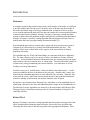
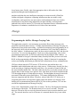
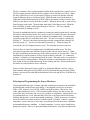
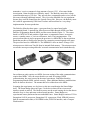
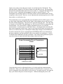
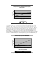
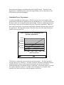
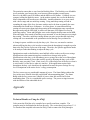
Message Ferry
Architecture and
Implementation
Master’s Project Report
Tammara Massey
Georgia Institute of Technology
April 28, 2004
Introduction
Motivation
In complex networks that contain a large variety in the density of the nodes, it is difficult
to provide reliable and efficient service. In sparse areas of the network, the mobility of
the nodes, the limited range of wireless communication, and physical factors such as
severe weather partition the network These network outages are an unacceptable dilemma
in networks that require reliability. Message Ferrying is a proactive routing algorithm
created to address network partitions in sparse networks by establishing non-randomness.
Message Ferrying is a proactive routing algorithm that incorporates message ferries or
mobile nodes that carry messages among disconnected nodes [21].
Even though the network may contain sparse regions, the ferry may become a point of
collision as all of the nodes try to connect and send information to the ferry. This
problem will be more evident in the ad hoc regions of the network that are densely
populated with nodes.
The embedded devices, iPAQ and Smart Badge, are concerned with power and battery
life. The most efficient way to save power is to have less hardware or more efficient
hardware. In this distributed-memory infrastructure that uses message passing, the nodes
only transmit to the ferry when the ferry is within range. Therefore, the nodes spend a lot
of unnecessary energy maintaining the network interface, even when there is no one
sending or receiving information.
In order to save power, a small sensor / radio was added to the infrastructure. A radio /
sensor was added to the ferry to broadcast a ferry message. Another radio / sensor was
added onto the embedded application to sense when the ferry is nearby. When the ferry
is detected, the sensor / radio turns on its network interface, and sends the information.
After the exchange of information, the network interface turns off again.
My objective is to implement the Message Ferry Algorithm on some embedded devices
minimizing collisions on the ferry and minimizing power usage on the embedded device.
The Message Ferrying Algorithm was created by a doctoral student called Wenrei Zhao.
The power usage was minimized using an idea of a doctoral student at Georgia Tech
called Hyewon Jun.
Related Work
Message Ferrying is a proactive routing algorithm that incorporates message ferries that
allow communication among disconnected nodes. Ferries travel in a specified route,
collecting data from sources and delivering data to the appropriate destinations. These
message ferries allow nodes to communicate when the network is disconnected and when
nodes do not have global knowledge of the network [21].
This algorithm is a good solution for sensor networks that may have several densely
disconnected sections that need to communicate with one another. The underlying
operating system used in many sensor networks was pioneered by TinyOS. This smart
dust is a tiny event driven operating system that provides multiple flows of data from a
single microcontroller [7].
With the emergence of advanced hardware and small operating systems, such as TinyOS,
new types of sensor networks began to appear. A less fine grained mote was used in
ZebraNet to track wildlife for biology research. This ad hoc peer to peer network was
energy-efficient and reliable as it used GPS to track Zebras movements in the wild by
using collars with sensors. A history based protocol that intelligently selected nodes
based on prior communication patterns proved to satisfy the tradeoffs between storage,
bandwidth, and energy requirements. This study was important because it demonstrated
how to forward data in regions where there is not any widely deployed
telecommunications support [6].
Another study called DataMULE addressed the problem of sparse area networks by using
a similar infrastructure that Message Ferrying uses. Mobile entities called MULEs pick
up data from sensors and drop off the data at wired access points. DataMULE takes a
layered approach and contains three tiers of WAN connected devices, mobile agents, and
sensor nodes. The MULE has low power requirements, low infrastructure cost, and large
storage capacities. However, the MULE experiences high latency [16]. DataMULE
differs from Message Ferrying because it uses static sensors and does not use proactive
movement to deliver data. Another study that address power management in sensor
networks is Mate. Mate, a tiny virtual machine for sensor networks, addresses the
problem reprogramming failing nodes in an energy efficient manner [10].
The emergence an intelligent sensor network called Sensor Web that was capable of
performing autonomous operation in uncertain environments. Sensor Webs are unique
because they have pods that gather information and shared the information with
neighboring pods. The collected data influences the behavior of these mobile pods and
allows for more efficient collection of data. It also provides heterogeneous
communication within the Sensor Web by allowing different kinds of pods to be added to
the network [4] [5].
Another study that addresses communication among heterogeneous devices is iMASH
(Interactive Mobile Applications Sessions Handoff) Project. iMASH created an
architecture for fast, secure wireless communication across heterogeneous client devices
and networks. iMASH utilized semantic savepointing, middleware only handoff, and
content adaptation to allow heterogeneous communication in a wireless network. First,
semantic savepointing identifies the essential state that needs to be sent for delivery. Then
in middleware handoff, the middleware server initiates the handoff of data resulting in a
lower latency time. Finally, only client appropriate data is delivered to the client
application through content adaptation [3].
Another study that also uses intelligent reasoning in a sensor network is PlantCare.
LaMarca designed a ubiquitous computing infrastructure that was usable, easily
configurable, and required no user intervention. Self-maintained robots were built to
automatically water plants using information on light, humidity, and temperature
gathered from wireless sensors [9]. This study was important because it demonstrated the
importance of continuous, automated service with no user intervention.
Design
Programming the Ad Hoc Message Ferrying Code
The application created is a text messaging system that allows short messages to be
passed back and forth between users. A simple implementation of Message Ferrying was
implemented using ad hoc networking. A problem encountered when programming in ad
hoc network is how to do the network address translation (NAT) from the IP address to
the MAC address. In infrastructure mode, the base station contains the NAT and does the
conversion. To overcome this problem, I used raw socket programming. Raw socket
programming bypasses the TCP/IP layer and sends data by using the MAC address. A
Master’s Student at Georgia Tech named Johnny Franslay had done previous work with
RAW socket programming and Message Ferrying. Johnny’s functions for opening the
sockets and sending information provided the basic infrastructure for my communication.
UDP was chosen instead of TCP because TCP with slow start and the three way
handshake make initialization and setup a slow process. With message ferrying, the ferry
can be traveling at a high speed and may only have a few seconds to connect to the ad
hoc network and transmit data. The time it takes for the ferry to join the network will cut
into the time for the message to be passed. Also, it has been proven from simulations that
TCP throughput drops a lot with node movement. The throughput decreases because the
movement of the nodes causes link failures. TCP cannot distinguish the difference
between congestion and link failure. Therefore, when a links fails, TCP believes it is
congestion and reduces its congestion window and in the instance of a timeout, starts
backing off its retransmission timeout (RTO) [8]. Due to these problems, TCP was not
used in the implementation of Message Ferrying.
In my code, I implemented a simple flow of control. The ferry first begins broadcasting
out messages to the nodes. The broadcast interval is set to two seconds. The node
however will not be able to receive the beacon because it has its network interface card
off. The network interface card is off because it is assumed that the ferry is not within
range.
The ferry contains a ferry signal transmitter and the node contains a ferry signal receiver.
The ferry signal generator notifies the ferry signal receiver that the ferry is near. When
the ferry signal receiver receives the signal, it brings up it network interface card and
begins to listen for the ferry broadcast signal. When the node received the beacon it
replies back with information about its MAC address and that it is ready to receive data.
If the ferry has data to send to the node, it sends it. When all data is sent, it sends a Ferry
Done Message to the node. The node then sends data if it has data to send. When the
node it finished, it sends a Node Done Message to the Ferry. The Ferry ends the
communication by sending an ACK.
The node is multithreaded and is continuously running the main program and is listening.
The node is either listening for the ferry sensor to turn on its network card or the node is
listening for the ferry beacon to open up a channel of communication. The main node
program provides the user with three basic tasks. The user can compose a message by
pressing “c”. The user can print out all messages already composed and waiting to be
sent by pressing “p”. The user can also quit by pressing “q”. When messages are
received they are also displayed on the screen. The messages are stores in queues.
After the flow of control was implemented, an additional problem arose. The ferry
experienced congestion and collisions when the nodes sent out data to the ferry. When
the ferry broadcasted out the message, all the nodes received it at the same time. They all
simultaneously sent their packets to ferry which resulted in collisions. To combat this
problem, a scheduler was implemented on all the nodes. When the nodes were initialized
they all received a random number. When they wanted to send information to the ferry,
they waited for the specified random time before sending the data. This desynchronized
the traffic flow and resulted in fewer collisions.
Future work for Message Ferrying would be to implement different versions, such as
Node Initiated Message Ferrying (NIMF) and Ferry Initiated Message Ferrying (FIMF).
In these versions, the location and the destination of the node and the ferry would have to
be tracked.
Selecting and Programming the Sensor Hardware
I investigated different types of sensor and radio technologies to optimize the embedded
application that would run on a smart badge. I investigated several types of sensors /
radios: GPS, Infrared, Active RF ID, CMOS, the Berkeley Mote, solar power, laser
radar, and transmitter/receivers. GPS was unacceptable because one has to know the
route of the ferry at all times and it was very expensive to implement. Infrared had a very
low transmission rate. Laser radar needed a clear line of site and would be blocked by
building and, therefore, was an unacceptable technology. CMOS, Solar powered sensors,
and Active RFid were either expensive or hard to attain. Primarily, I choose a simple
transmitter / receiver because it was easily accessible and was the most basic, affordable,
and attainable hardware candidate. A simple transmitter / receiver can be found in any
garage door opener. However, upon purchasing the hardware, it was discovered that the
transmitter / receiver consumed a large amount of power (12V). After some further
investigation, I then decided to use Berkeley motes. The Berkeley motes have a large
communication range of 250 feet. They not only have a transmitter and receiver, but the
kits came with many additional sensors. They were also affordable for our experiment
because they could be loaned from the Systems Group Lab. However, the Berkeley mote
kit is sold for approximately $500 from Crossbow and would not be a very cheap
implementation for mass production.
The Berkeley Mote has three parts: a processor board, a sensor board, and a
programming board. I attained four Mote Processor Radio Boards (MPR), two Mote
Interface Programming Boards (MIB), and four sensor boards (Figure 1). The sensor
board is a MTS310CA and contains a light sensor, a temperature sensor, an acoustic
sensor, a sounder sensor, a 2-axis accelerometer, and a 2-axis magnetometer. The
processor board that is used to program the processor is a MDA500CA data acquisition
board that provides a flexible user-interface for connecting external signals to the mote.
The processor board is a MPR400CA. The MPR400CA uses an Atmel ATmega 128L
microprocessor which runs TinyOS from its internal flash memory. This microprocessor
can run the sensor processing and radio / network communication stack simultaneously.
Figure 1: Mote Interface Programming Board, Mote Processor Radio Boards, and a Sensor Board.
Our architecture only requires two MPRs, but some testing of the radio communications
require three MPRs. Also, the sensor boards were used for testing of MPR
communication, but were not used in the actual experiment. Both Mote Interface
Programming Boards (MIB) worked correctly. Some additional hardware modifications
had to be done to the motes. The antenna had to be soldered on to the MPRs. .
In running the experiments, we also have to take into consideration the Smart Badge
itself. The Smart Badge shown in Figure 2 is the device that will have its network
interface turned on and off. The Berkeley motes are the actual sensing device that detects
when the ferry is close and turns on the network interface. Smart Badges are
experimental sensor platforms that run embedded Linux. Smart Badges consists of 32-bit
StrongArm SA1110 processors, StrongArm1111 coprocessor, Flash, SDRAM, sensors,
built in communication links, a SO-DIMM socket, PCMCIA interface, and a Compact
Flash interface.
Figure 2: Front Side of Smart Badge4
The documentation for the TinyOS and NesC, the programming language is not good.
NesC is a new structured component-based language primarily used for embedded
systems, such as sensor networks. In addition to learning a new programming language,
other difficulties had to be overcome. First, the wrong version of the software was
included with the Crossbow TinyOS CD. It included the software and instructions for
Mica hardware, whereas I have Mica2 hardware. Also, a printer cable was used when
downloaded the code to the mote, but the COM1 port was used when communicating
with the smart badge. Many environmental variables in odd files had to be changed
because Mica2 runs at 57.5K baud and the sensor board is a micasb not a basicsb. The
basicsb is the sensor board for the more generic Berkeley motes. A Makelocal file had to
be created to set the power to 916MHz and set the group ID. The group ID in the
message header allows several groups of motes to share the same radio channel. After
these interesting difficulties were overcome, I wrote the program for the ferry sensor in
NesC to communicate as in the below diagram (Figure 3).
Figure 3: Communication Architecture Between Two Mote Sensors and a Base Mote
Experimental Results
Berkeley Mote Experiments
I modified two things in the Berkeley mote: the transmission power and the duty cycle.
The transmission power affects the range of the ferry sensor. The range of the ferry
sensor is directly proportional to how much power the sensor will use. The longer the
range, the more power the sensor will use. Therefore, I performed two power
adjustments to the sensor. To extend the range of communication, I also modified the
network’s communication to include multi-hop routing. In multi-hop routing, one sensor
broadcasts out to other sensors that the ferry is within range (Figure 4). Multi-hop
communication is especially useful in architectures where the sensors have a low
Sensor
Ferry
Single Hop
Smart
Badge
Sensor
Smart
Badge
Sensor
Smart
Badge
Multi -Hop
Multi -Hop
Figure 4 Single and Multi-hop Routing in Message Ferrying
transmission range because multi-hop communication will increase the amount of time
the device has to communicate with the ferry. Our particular ferry sensor is the Berkeley
Mote with a very long range of 250 feet. Therefore, we did not implement multi-hop
communication. However, this data will be useful in future implementations where the
price of the ferry sensor must be cheap. During the analysis of different types of sensors,
I discovered that the range of the sensor was inversely proportional to how much the
sensor cost.
Figure 5 illustrates how higher transmission powers result in a longer communication
range. Data in this graph was collected from the MPR /MIB User manual [12]. Some
preliminary tests were done with the mote to verify its communication range. At the
lowest setting, the MPR should have a range of 10 feet. However, the mote still
transmitted at the maximum range of our experiment of 25 feet.
Variation in Communication Range
Caused by Transmission Power
Communication Range
(feet)
350
300
250
200
150
100
50
0
-25
-20
-15
-10
-5
0
5
10
Transmission Power (dBm)
Figure 5: Affect of Transmission Power on Radio Range
The speed of the ferry also affects the connectivity time between the device and the ferry.
The sensor must be able to detect the ferry in time for the node to connect to the ferry and
send information. If the range is not long enough, then the node will not have enough
time to connect and finish transmission before it is out of range. A study was done by Ott
and Kutsher with Wireless LAN communication and automobiles. In their experiments,
they proved that a single access point had a reach of at least 200 meters in diameter with
one IEEE 802.11b access point. Also, they concluded that the coverage obtained from a
How the Speed of the Ferry Affects
Throughput
Throughput (Kbps)
200
150
100
50
0
0
10
20
30
40
50
Miles per Hour
Throughput (1250 byte packets)
Figure 6: Speed of the Ferry and Throughput
60
single access point is more than ten seconds, even at high speeds of 180 km/hr. They
state that it takes 300ms for 1250 bytes of data to be sent and received. The beacon that
detected the automobile had an interval of one second [13]. Using this information from
the above study, I calculated the throughput in relation to speed in Figure 6. The
assumption was used that packets of 1250 byte packets were used and that there was no
congestion in the network. However, in our experiment the maximum packet size is 5000
byte packets, so results may vary.
The transmission power is programmable and controlled by the PA_POW register. There
are three main components on the board in Figure 8 that consume power: the processor,
the radio, and the data logger. The processor is an Atmel ATmega 128L. The radio runs
at frequency of 916 MHz. The data logger is a 4M-bit serial FLASH for storing data and
measurements. The serial FLASH / Logger component can store over 100,000
measurements. I measured power of the entire board. I investigated also measuring the
three main components on the board. However, the chips on the board were not set up to
allow me to measure the power consumption without major changes to the MPR board.
In order to measure the power consumption on the MPR board the wires connecting to
the battery had to be cut and modified to allow me to attach it to a multimeter. I used a
Craftsman 82002 Multimeter for this experiment. The results of the transmission power
experiment done on single and multi-hop routing is shown in Figure 7.
Power Consumption Due to Transmission
Power
70
Power (mW)
60
50
Single Hop
Routing
40
Multi-hop Routing
30
No LEDS
20
10
0
-20
-10
0
Output Power (dBm)
Figure 7: Power Utilization for a Berkeley Mote with Varying Transmission Powers
I also adjust the power by adjusting the duty cycle in the single hop communication
architecture. Duty cycle is the proportion of time in which the device is operated. The
more a component is used the quicker it will wear out. In regards to power, lowering the
duty cycle reduces the power as seen in Figure 8. When measuring the power with
Analysis of Power Utilization with Varying
Duty Cycles
Power (mW)
25
20
15
10
5
0
0.00%
20.00%
40.00%
60.00%
80.00%
100.00%
Duty Cycle
Low
High
Figure 8: Power Utilization for a Berkeley Mote using Varying Duty Cycles
varying duty cycles, there was an observation made that the numbers fluctuated on the
multimeter. This was due to the fact that the processing would be reduced during the
inactive part of the cycle and then jump up during the active part of the cycle. Therefore,
there is a high and a low value for the testing of the duty cycle. The multimeter would
read the low for the majority of the time and shoot up to the high when the processor
became busy. As the duty cycle was lowered, the range between the high and the low
increased. However, adjusting the duty cycle does have some negative affects on the data
rate. As the can be seen in Figure 9, decreasing the duty cycle reduces the data rate [19].
Affect of Duty Cycle on Packet Rate
Data Rate (kbps)
50
40
30
20
10
0
0%
20%
40%
60%
80%
100%
Duty Cycle (Percentage)
Max Packet Rate
Effective Packet Rate
Figure 9: Duty Cycle Modes and Their Corresponding Data Rates
Data used in the diagram was obtained from the TinyOS Tutorial. Therefore, in our
application we should be cautious when lowering the duty cycle to ensure that we can
still maintain our desired throughput.
Embedded Device Experiments
In order to determine the effectiveness of the ferry sensor, Hyewon, Jeonghwa, and I
performed several different experiments on the embedded device. The amount of power
the ferry sensor uses is drained from the Smart Badge. Therefore, minimizing the power
that the ferry sensor uses will minimize the power of the entire application. Figure 10
shows how much power is used on the smart badge with and without the ferry sensor in
the application. The longer the lifetime of the ferry sensor, the more time the network
interface mode would be off.
Power Utilization on the SmartBadge with
Hardware Optimization
Power (mW/min)
600000
500000
400000
300000
200000
100000
0
0
200
400
600
800
1000
Route time (minutes)
Original Message Ferrying
Hardware Optim ization
Figure 10: Power of Smart Badge With and Without The Ferry Sensor.
The latency to resume the network interface was also measure. The ferry broadcast
message interval was reduced to 5 µseconds. Therefore, the latency measured would be
dominated by how long it took to resume the interface, not by the period of the
broadcasted message. As shown in Figure 11 and Table 1, the average latency to resume
the wireless interface is only 237 µseconds. Since the latency is very small, it will
probably have little to no effect on the throughput of the device.
Figure 11. The Normal Distribution Of Resuming Latency In Ad Hoc Mode.
Resume Latency of the Smart Badge and Berkeley Mote
Mean latency
237.230 msec
Standard deviation
21.655
Table 1: The Mean Latency and Standard Deviation of Resume Latency in Ad Hoc Message Ferrying
Conclusion
As can be seen from the results, using the ferry will save a considerable amount of power
in the smart card. The larger the route of the ferry, the more power is saved. Also, it can
be concluded that changing the transmission power had little affect on the power
utilization in both the single and multi-hop experiments. This may be due to the fact that
the Berkeley mote was specifically designed to save power and a lot of power
optimizations in regards to transmission power have already been done. Therefore, it
would be beneficial to use the highest transmission level to communicate in the Message
Ferry Architecture. From these transmission experiments, it can be ascertained that the
utilization of the LED lights had an affect on the power utilization. The utilization went
up and down in the graphs. This was due to the fact that the green LED light was toggled
off and on with each transmission. An explanation for why the transmission power did
not change the power of the badge could be that it was because the function to control the
transmission power is not implemented correctly in the TinyOS Kernel. The command
Pot and SetTransmission Power were implemented on the lowest setting and it still had a
range of over 25 feet instead of 10 feet. TinyOS still has bugs and the Transmission
Power may not be implemented correctly in the code.
The particular sensor that we used was the Berkeley Mote. The Berkeley was affordable
in our particular case because they were borrowed from another research group.
However, the MPR costs $150 dollars and the MIB cost $95 dollars. Crossbow is a new
company selling the Berkeley motes. As the market expands, the cost for the Berkeley
Mote components will become more affordable. Another alternative is to use a sensor
with a lower range and use multi-hop routing. Using multi-hop routing will aid in
extending the range of the ferry, but more studies need to be done to quantify the exact
relationship this would have on distance. At a first glance, it seems that multi-hop
routing uses more power than single hop routing in the transmission range experiment.
But upon analyzing the LED light, it can be seen that more LED lights were used in
multi-hop routing. Green and red lights were used to display the hop count on the MPR.
When the lights were turned off and the power measured, it was the same power as single
hop routing. Therefore, multi-hop routing did not use more power than the single hop
routing and is recommended as an optimization in the Message Ferry architecture.
A change in power could be seen by the duty cycle. However, one must be cautious
when modifying the duty cycle in order to ensure that the throughput is enough to get the
data to the ferry before it goes out of the range. Therefore, the specific application needs
to be analyzed when determining to adjust the duty cycle.
Optimizations made on the Berkeley mote had little affect on the overall power savings.
Modifications to the transmission power resulted in no change in the power.
Modifications to the duty cycle did enhance power savings, but at the cost of throughput.
The maximum amount of power that could be saved by adjusting the duty cycle on the
Berkeley mote was only 15mA. 15mA is only 2% of the total power of the device when it
is active and 6% of the device when it is inactive. If the application requires high
throughput, the duty cycle should not be optimized because the power savings are very
low in comparison to the entire device’s energy consumption.
The ferry sensor saves a considerable amount of power. The Smart Badge without the
ferry sensor uses 590mW when idle and 604mW when transmitting data. The Smart
Badge with the ferry sensor uses 240mW of power when idle and 604 mW when
transmitting data. This is a considerable power savings. The power savings increases
with the lifetime of the embedded device.
Appendix
Technical Details on Using the iPAQ
Code ran on the iPAQ has to be compiled on a specific arm-linux compiler. The
compiler must be downloaded in the root directory. The version that was used was 3.3.1.
To download the compiled code onto the iPAQ, I had to connect the iPAQ through a
serial cradle to a COM port in a laptop or PC. Minicom and Teraterm should then be
used and the download should be done using the ZModem. The source and destination
directories and the baud rate of 115200 must be specified in Minicom. I had difficulties
with the Minicom application in Linux and used Teraterm. When compiling, I used the
downloaded directory of /usr/local/arm/3.3.1/bin/gcc in the Makefile. Also, ensure that
the iPAQ is running the orinoco_cs module and not the wavelen_cs module for the
network driver. The wavelen_cs module has bugs and has been discontinued.
Technical Details on Using the Smart Badge
Code ran on the Smart Badge had to be compiled on a specific arm-uclibc compiler. This
compiler must also be downloaded in the root directory. The version that was used was
3.2. To program and download code onto the Smart Badge, a COM cord was used while
running Teraterm. The power supply must also be connected to the badge for it to
function properly. The sensor drivers must be loaded with the command modprobe
badge4_sensors. NFS must be running on the machine running as the server where the
code is compiled. The Smart Badge is mounted with the command mount –o
rw,nolock,intr 192.168.1.220:/home/badge0 /opt/Badge4. 192.168.1.220 is the IP
address of the server. /home/badge0 is the directory on the server where the code is
changed and can be compiled. Opt/Badge4 is the directory on the badge where the
information will be stored. The code is compiled by typing arm-uclibc-gcc filename.txt.
Technical Details on Using the Berkeley Mote
Code ran on the Berkeley Mote had to be compiled using the TinyOS software. The code
written was in an embedded C language called NesC. The version used for this
experiment was 1.1 and the Motes used were Mica2. To compile the code the command
make mica2 is used. To download the code onto the mote, the command make mica2
install. When setting up the software many variables must be changed and set. Ensure
that the baud rate is set to 57.5K, the sensor board is set for micasb when using mica2
motes, and that a Makelocal file is created to set the power to 916MHz and set the group
ID. The group ID in the message header allows several groups of motes to share the
same radio channel. Check to ensure that the software and instructions match each other
and also the actual motes that you received. The software did not match the motes on the
Crossbow CD. Also, a printer cable should be used to download the code to the mote and
the COM1 port should used when communicating with the smart badge. The COM1
cable requires a female to female connection.
Recommendation for Future Message Ferrying Lab
I recommend using some of these embedded technologies in future research with
Message Ferrying. The three embedded devices that I used would be good for testing
different types of wireless communication. The iPAQ is especially useful due to its
lightweight size and portability. The Berkeley Motes were excellent in developing a
wide variety of applications. The Berkeley Motes contain a light sensor, a temperature
sensor, an acoustic sensor, a sounder sensor, a 2-axis accelerometer, and a 2-axis
magnetometer. They are also portable and use very low power as can be seen from our
experiments. The Smart Badge 4 is also a good embedded platform for sensors with a
stronger processor than the Berkeley motes. Sensors, such as accelerometers, biometrics,
and imaging sensors, may also be connected to the Smart Badge. It supports audio
processing, such as speech, noise cancellation, and streaming audio. Video streaming
and VoIP can also be done on the Smart Badge.
Also, more complex versions of Message Ferrying involved tracking location. GPS
tracks location but only outside and the measurements are not very precise. Another
suggestion is to use laser radar. Laser radar has a range of 100 meters. The angle that the
beam is reflected back to the source is calculated to tell the destination of the other entity.
However, a clear line of site is required and any type of obstruction such as a building
will not allow this type of technology to work. In addition to this deficiency, laser radar
is quite expensive ranging from $200 – $3000.
Acknowledgements
I would like to thank Professor Hutto for loaning the Berkeley Motes for this Experiment.
I would also like to thank Johnny Franslay whose raw socket functions for Message
Ferrying were used in my Ad Hoc message ferrying code. Johnny also aided with
technical help on the iPAQs and WLAN. I would like to thank Hyewon Jun for
suggesting the power savings hardware optimization and also programming the serial
port information. I would like to thank Professor Mark Smith from Hewlett Packard
Labs for loaning me the Smart Badge and also aiding with power measurements on the
Smart Badge and Berkeley Motes. I would also like to thank Jeonghwa Yung who
programmed Infrastructure Message Ferrying on the Smart Badge (this application is not
covered in this report.)
References
[1] I. Akyildiz, W. Su, Y. Sankarasubramaniam, and E. Cayirci, "Wireless Sensor Networks: A Survey,"
Computer Networks Journal, Vol. 38, no. 4, pp. 393-- 422, 2002.
[2] M. Ammar and et al. “Report of NSF Workshop on Fundamental Research in Networking.” NSF
Workshop on Fundamental Research in Networking, Airlie, Viginia, April 2003.
[3] R. Bagrodia and etc. “iMASH: Interactive Mobile Application Session Handoff.” In Proceeding of
MobiSys, May 2003.
[4] K. Delin and S. Jackson. "The Sensor Web: A New Instrument Concept." In the Proceedings of the
SPIE Symposium on Integrated Optics, San Jose, CA, January 2001.
[5] K. Delin. "Sensor Web: A Macro-Instrument for Coordinated Sensing." In Sensors, Vol. 2, 2002, pp.
270-285.
[6] P. Juang and et al. “Energy-efficient Computing for Wildlife Tracking: Design Tradeoffs and Early
Experiences with ZebraNet. In the Proceedings of International Conference on Architectural Support for
Programming Languages and Operating Systems (ASPLOS), San Jose, CA, October 2002.
[7] J. Hill and et al. "System Architecture Directions for Networked Sensors." In the Proceedings of
International Conference on Architectural Support for Programming Languages and Operating Systems
(ASPLOS), Cambridge, MA, November 2000.
[8] G. Holland and N. Vaidya. "Analysis of TCP Performance over Mobile Ad Hoc Networks." In the
Proceedings of ACM/IEEE International Conference on Mobile Computing and Networking (MobiComm).
Seattle, Washington. August 1999.
[9] A. LaMarca, and etc. “Plantcare: An Investigation in Practical Ubiquitous Computing Systems”, In
Proceedings of Ubicomp 2002, pp. 316-332, Goteborg, Sweden, Sep. 2002.
[10] P. Lewis and D. Culler. "Mate: A Tiny Virtual Machine for Sensor Networks." In the Proceedings of
International Conference on Architectural Support for Programming Languages and Operating Systems
(ASPLOS), San Jose, CA, October 2002.
[11] R. Mancini. "Instrumentation: Sensors to A/D Convertors." Op Amps for Everyone. Texas
Instruments, 2nd ed. Dallas, Texas: Newnes, 2003. 12.1 - 12.23.
[12] “MPR / MIB Mote User’s Manual”. Crossbow Technology, Inc. San Jose, California. 2003.
[13] J. Ott and D. Kutscher. "Drive-thru Internet: IEEE 802.11b for 'Automobile' Users." In Proceedings
of InfoComm. Hong Kong, China. March 2004.
[14] P. Pirjanian, T.L. Huntsberger, and P. S. Schenker, "Development of CAMPOUT and Its Further
Applications to Planetary Rover Operations: A Multirobot Control Architecture," In Proc. SPIE Sensor
Fusion and Decentralized Control in Robotic Systems IV, Vol. 4571, Newton, MA, Oct. 28-29, 2001.
[15] P.S. Schenker, P. Pirjanian, T.L. Huntsberger, A. Trebi-Ollennu, H. Aghazarian, P.C. Leger, JPL; S.
Dubowsky, MIT; G.T. McKee, Univ Reading (UK), "Robotic intelligence for space: Planetary surface
exploration, task-driven robotic adaptation, and multirobot cooperation," In Proc. SPIE Symposium on
Intelligent Robots and Computer Vision XX: Algorithms, Techniques, and Active Vision, Vol. 4572,
Newton, MA, Oct 29-31, 2001.
[16] R. Shah and et al. "Data MULEs: Modeling a Three-tier Architecture for Sparse Sensor Networks."
In Proceedings of the IEEE Workshop on Sensor Network Protocols and Applications (SNPA), Anchorage,
AK, May 2003
[17] J. Singh and etc. "Wireless LAN Performance Under Varied Stress Conditions in Vehicular Traffic
Scenarios." In the Proceedings of IEEE Vehicular Technology Conference. Vol. 2, Vancouver, Canada.
September 2002.
[18] A. Sipitakiat. "Making Sensors." GoGo Board. Rev. 0.91. http://learning.media.mit.edu/projects/
gogo/new/documents/making%20sensors.html.
[19] Tiny OS Tutorial. “MICA2 Radio Stack for TinyOS.”
[20] H. Zeng and et al. "ECOSystem: Managing Energy as a First Class Operating System Resource." In
the Proceedings of International Conference on Architectural Support for Programming Languages and
Operating Systems (ASPLOS), San Jose, CA, October 2002.
[21] W. Zhao and M. Ammar, "Message Ferrying: Proactive Routing in Highly-Partitioned Wireless Ad
Hoc Networks." In Proceedings of the 9th IEEE Workshop on Future Trends in Distributed Computing
Systems, Puerto Rico, May 2003.
[22] W. Zhao and M. Ammar. "A Message Ferrying Approach for Data Delivery in Sparse Mobile Ad Hoc
Networks." To appear in MobiHoc, Tokyo, Japan, May 2004.