1
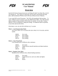
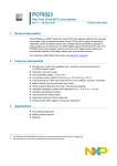
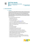
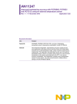
I2C 2005-1 Demonstration Board
Temperature Sensors
Oct, 2006
Local versus Remote Temperature Sensors
Local Temperature Sensor
Senses own die temperature
Local & Remote Temperature Sensor
Senses own die temperature AND
that of the remote diode sensor
Remote Diode Sensor
Part#
Local Sensor
Accuracy
Remote Sensor
Accuracy
Part#
Accuracy
SMBUS TIMEOUT
LM75A
+ 2 oC
NO
NE1617A
+ 2 oC
+ 3 oC
SE95
+ 1 oC
NO
NE1619*
+ 3 oC
+ 5 oC
SE98
+ 2 oC
YES
SA56004
+ 2 oC
+ 1 oC
Note: * with voltage monitors
2
I2C 2005-1 Demonstration Board Oct, 2006
SE98 Local Temperature Sensor
Local temperature sensor compliant to JEDEC JC42.4
SE98 accuracy of ±2 oC (75 to 90 oC)
11-bit (0.125 °C) resolution
With SMBus TIMEOUT
& Security lock bits
8 Hz minimum conversion rate
0 °C, 1.5 °C, 3 °C, 6 °C programmable hysteresis
threshold
EVENT# output associated with 3 alarms: upper, lower and
critical
Block Diagram
Security lock bit for data protection
Operating voltage range from 3.0 V to 3.6 V
11-bit
ΔΣ
A-D-C
A0
Maximum operating current: 250 µA
A1
Programmable SMBus Alert Response and TIMEOUT
A2
Operating temperature range from –20 °C to +125 °C
3 programmable I2C address pins: 0011 [A2 A1 A0]
GND
VDD
EVENT
Security Lock Bits
2-wire SMBus or I2C-bus standard/fast mode compatible
Temperature
Register
CriticalTemperature
OverTemperature
UnderTemperature
Configuration
Control Logic
2-wire I2C/
SMBus
Interface
SCL
SDA
Offered in TSSOP8 and HVSON8* package
*Note: 3mm x 3mm
3
I2C 2005-1 Demonstration Board Oct, 2006
Excellent Accuracy Characteristic
SE98 Temperature Accuracy
25 Devices Tested @VCC = 3.3 V
From 25 Devices
• Temperature accuracy is
well controlled over the
entire
temperature range
1.5
1
0.5
0
-0.5
• Lot to lot variation may
shift
the accuracy up or down
-1
-1.5
120
100
Temperature (oC)
80
60
40
20
0
-2
-20
Temperature Accuracy (oC)
2
4
I2C 2005-1 Demonstration Board Oct, 2006
Temperature Accuracy Versus Resolution
Temperature Resolution
Temperature Accuracy
Accuracy and error are used
synonymously, and is the measure of
how precisely the temperature sensor
reading matches the ambient
temperature
Is the measure of temperature
sensor’s smallest measuring step
Example of 0.125 °C resolution
Example: ±2 °C accuracy
Measured Temperature
Actual measured
Temperature 75.125 °C
73 oC
75 oC
75 oC
+ 2 oC
77 oC
Ambient Temperature
5
I2C 2005-1 Demonstration Board Oct, 2006
Comparator versus Interrupt Mode
Comparator mode:
EVENT output is cleared by itself once the temperature drops below the setpoints
Interrupt mode:
EVENT output is latched and only cleared by writing to the clear event bit
6
I2C 2005-1 Demonstration Board Oct, 2006
Configuration Register
Critical Lock Bit
0: alarm register not locked, register value can be changed
1: alarm register locked , register value cannot be changed
ALARM Lock Bit
0: Alarm not locked, upper and lower alarm can be modified
1: Alarm locked, upper and lower alarm cannot be modified
Clear EVENT flag
0: no effect
Hysteresis for alarm
1: clear the event flag in interrupt 00:
mode
hysteresis disabled
01: hysteresis = 1.5 °C
10: hysteresis = 3 °C
11: hysteresis = 6 °C
0: Temp sensor shutdown mode
1: Normal mode
Register is 2 Byte
EVENT Status bit
0: not asserted
EVENT output control bit
1: asserted
0: EVENT output disabled
1: EVENToutput enabled
Critical EVENT Only
0: Critical+Alarm
1: Critical
EVENT Polarity
0: Active low
1: Active high
EVENT Mode
0: Comparator mode
1: Interrupt mode
7
I2C 2005-1 Demonstration Board Oct, 2006
SE98 Registers
8
I2C 2005-1 Demonstration Board Oct, 2006
Temperature Data Register
Above Critical indicates whether the temperature exceeds the critical temperature
0: temp is below critical temperature
1: temp exceeds critical temperature
Above ALARM window indicates whether the temperature exceeds the alarm temperature
0: temperature is below the upper alarm
1: temperature exceeds the upper alarm
Register is 2 Byte
Below ALARM Window indicates whether the temperature falls below the lower alarm
0: temperature is above the lower alarm
Sign bit
1: temperature falls below the Lower ALARM
0: positive temperature
1: negative temperature
1
1
1
1
Integer
Decimal
Reserved for future use
Temperature Value = 25.125 oC
9
I2C 2005-1 Demonstration Board Oct, 2006
SE98 Training Board Schematic
PCA9541/01
SE98
Address: 0x30
EVENT Output LED
Visual status: Interrupt input and outputs
10
I2C 2005-1 Demonstration Board Oct, 2006
Training Board: Hardware Introduction
11
I2C 2005-1 Demonstration Board Oct, 2006
SE98 Software GUI
Device Æ Thermal Management Æ SE98
Temperature Reading
Alarm Status bits
Cyclic
Read
Device
Address
Configuration
& Status
Registers
Auto
write
Alarm
setpoints
12
I2C 2005-1 Demonstration Board Oct, 2006
SE98 Hands-On: Device Initialization
Set critical boundary alarm trip to 80 °C boundary registers
Set hysteresis to
1.5 °C
Set upper boundary alarm trip to 27 °C
Enable
/EVENT
output
Autowrite ON
Transmission
Successful
Indicates SE98
responding
13
I2C 2005-1 Demonstration Board Oct, 2006
SE98 Hands-on (2) – EVENT output in
Comparator versus Interrupt Mode
1.
Visually check EVENT LED – it should be OFF
2.
Click on the “Cyclic read” for continuous temperature update
3.
Heat up or place your finger over the SE98 for a few minutes for temperature to exceed
28 °C, the EVENT LED is ON
4.
Cool down or remove your finger from the SE98 and wait for a 1 minute or 2 until the
temperature drops below 28 °C
– What happens to the EVENT LED now?
•
5.
Change the EVENT output to Interrupt mode and repeat steps 1-4.
– What happens to the EVENT LED now?
•
6.
EVENT LED is OFF
EVENT LED is still ON
Clear the EVENT bit.
• EVENT LED is OFF
Conclusion?
– Comparator mode, the EVENT output de-asserted and LED is OFF when
temperature falls within the ALARM window
– Interrupt mode, the EVENT output stays asserted and LED is ON even after the
temperature drops back within the ALARM window. The output is cleared by writing
to the “event clear bit”
14
I2C 2005-1 Demonstration Board Oct, 2006
SE98 Hands-on (cont.) – Security lock bits
1. Read the upper, lower and critical alarm boundary trips registers.
What are their values?
Upper = 28 oC; Lower = 0 °C; Critical = 85 °C
2. Change the upper, lower and critical alarm boundary trip to 35 °C,
-20°C, and 125 °C and read them back. What are their values?
Upper = 35 °C
Lower = - 20 °C
Critical = 125 °C
3. Check the “lock the Critical” and “lock alarm window” bits
4. Change the upper, lower, and critical alarm boundary trips to 28 °C,
0 °C, and 85 °C, and read them back. What are their values? No
change
5. Remove the power will reset remove the lock feature
Conclusion: lock bit protects alarm setpoint values. Once lock bit is
written, you can only clear it by powering off the SE98.
15
I2C 2005-1 Demonstration Board Oct, 2006
Expert Mode Exercise
Power off and on the board
Use the Expert Mode, write and verify the following codes:
1.
2.
3.
4.
5.
6.
7.
8.
Set the upper alarm to 27 °C
Confirm what you wrote is correct
Set the critical temperature to 70 °C
Confirm what you wrote is correct
Write to configuration register to enable the EVENT output
Read what you’ve just wrote
Heat up SE98 and read the configuration register
Read the temperature value
16
I2C 2005-1 Demonstration Board Oct, 2006
Solution
17
I2C 2005-1 Demonstration Board Oct, 2006
SA56004 Local & Remote Temp Sensor
Monitors remote and local temperatures
Accuracy of ±1 °C remote temperature sensing
11-bit ADC or 0.125 °C resolution
Offset registers for the remote sensing accuracy
ALERT#/T_CRIT# output for interrupt/fan control
(on/off)
2-wire SMBus, or I2C standard/fast mode
compatible
+1 oC Accuracy
With fan control
Supports SMBus ALERT Response and TIMEOUT
One-shot control for power saving
Programmable Fault Queue
Diode fault detection
Up to 8 different device addresses
Offered in TSSOP(MSOP)8 and SO8 packages
18
I2C 2005-1 Demonstration Board Oct, 2006
SA56004 Block Diagram
19
I2C 2005-1 Demonstration Board Oct, 2006
SA56004 Registers
20
I2C 2005-1 Demonstration Board Oct, 2006
Configuration and Status Registers
Configuration Register (1 Byte)
Write addr = 09h; Read addr = 03h
Status Register (1Byte)
Read addr = 02h; Write addr = N/A
21
I2C 2005-1 Demonstration Board Oct, 2006
SA56004 Training Board Schematic
ALERT
T_CRIT
Connects
To PCA9538
Port 7 and 8
PCA9538
ALERT
Status
LEDs
T_CRIT
Status
LEDs
SA56004
22
I2C 2005-1 Demonstration Board Oct, 2006
SA56004 Software GUI
Device Address 0x98
Local Temperature
Remote temperature
Status Reg
Temperature
HIGH/LOW
Limits
Config Reg
Critical
Temperature
Limit
Conversion
rate
Autowrite
Offset reg
Cyclic read
1-shot
23
I2C 2005-1 Demonstration Board Oct, 2006
SA56004 Exercise
1.
Select “cyclic read”
2.
Read the status and configuration registers. What are the bits?
–
all bits should be clear
3.
Set the remote high set-point register to 50 °C,
4.
Set remote low set-point to 10 °C, and remote T_CRIT to 60 °C
5.
Place the remote sensor diode in the hot water and record the remote temperature reading
6.
Read the status register. Which bit is asserted?
–
External high temp bit is set
7.
Place the remote sensor diode in a cup of ice water for 2 minutes or more
8.
Read the status register. Which bit(s) is asserted?
–
External low temp bit is set
9.
Read the local temperature value
–
Room temperature
10.
Put the device in standby mode, place your finger over the SA56004, What happens to the local and
remote temperature reading?
–
No change
11.
Keep the finger on the SA56004 and click on the one-shot push button. What happens to the local and
remote temperature reading?
–
Updated to your body temperature
24
I2C 2005-1 Demonstration Board Oct, 2006
Expert Mode Exercise
Power on and off the board
Use the expert mode, write and verify the following codes:
1.
2.
3.
4.
5.
6.
7.
Program SA56004 to standby (STOP) mode in the configuration register
Program the pointer to the remote temperature register high byte
Read the remote temperature data register high byte
Program the pointer to the remote temperature register low byte
Read the remote temperature data register low byte
Issue a one-shot command
Read the remote temperature data high and low byte (repeat steps 3 and
5)
25
I2C 2005-1 Demonstration Board Oct, 2006
Solution
26
I2C 2005-1 Demonstration Board Oct, 2006
Temp Sensors Selection Table
Voltage Remot
Monitor e/Local
Local
Part#
Tem perature
range
Accuracy
Resolution
Local
Rem ote
Pow er
Supply Range
Supply current
Operting Shutdow n
2.7 V to 5.5 V
1 mA
3.8 μA
2.8 V to 5.5 V
1 mA
7.5 μA
N/A
+-1 oC
+-3 oC
+-1 oC
0.125 oC / LSB
0.03125 oC /
LSB
0.125 oC / LSB
0.125 oC / LSB
1 oC / LSB
0.125 oC / LSB
to 3.6 V
to 3.6 V
to 5.5 V
to 3.6 V
100 μA
500 μA
70 μA
80 μA
10 μA
3.5 μA
3 μA
+-3 oC
1 oC / LSB
2.8 V to 5.5 V
500 uA
100 μA
LM75A
-55 oC to 125oC
+-2 oC
N/A
SE95
-55 oC to 125oC
+-1 oC
N/A
SE98
SA56004
NE1617A
NE1618
-20 oC to 125oC
-55 oC to 125oC
-55 oC to 125oC
-55 oC to 125oC
+-2 oC
+-2 oC
+-2 oC
+-2 oC
NE1619
-55 oC to 125oC
+-5 oC
3.0 V
3.0 V
3.0 V
3.0 V
27
I2C 2005-1 Demonstration Board Oct, 2006
Temperature Sensor Applications
CONSUMER
COMMUNICATION
COMPUTING/STORAGE
PC
SO-DIMM
INDUSTRIAL
Laptop
Server
28
I2C 2005-1 Demonstration Board Oct, 2006