1
C S M 1 2 C 3 2
J U N E
8 ,
2 0 0 5
Communications
The CSM12C32 module provides a single RS-232 communications port. An RS-232 transceiver (U2) provides RS-232 signal level to TTL/CMOS logic level translation. RS232 signals
TXD and RXD are routed between the transceiver and the MCU. These signals are also
routed to connector J1. RS-232 communication signals input on J1 must be TTL/CMOS logic
levels; no translation support is provided through this path. The transceiver output may also
be driven off-module if the signals are suitably buffered. As added development support,
hardware flow control signals RTS and CTS are available on the logic side of U2. These signals are routed to vias located near the transceiver (U2). RTS has been biased properly to
support 2-wire RS-232 communications.
Use of the J1 connector to input RS-232 signals requires disabling the on-board RS-232 transceiver. Otherwise, signal corruption may occur. Disabling the on-board transceiver is accomplished by opening cut-traces CT1, and CT2. Simply remove the circuit trace between the cuttrace pads to open the circuit. To restore the circuit functionality, install a 1206 size, 0-ohm,
resistor or a short piece of wire across the cut-trace pads.
Table 1: Serial COM Signals
COM Signal
TXD
RXD
MCU Port
PS1/TXD
PS0/RXD
Connector
J1-5
J1-7
Disable
CT5
CT4
COM Connector
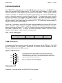
A standard 9-pin Dsub connector provides external connections for the COM port. The COM
port is configured as a DCE device. Component U2 provides RS-232 translation services.
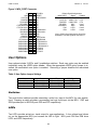
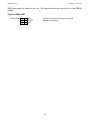
The figure below shows the DB9 connector.
Figure 2: COM Connector
1
6
TXD
2
RXD
3
7
RTS
8
CTS
9
NC
4
GND
Female DB9 connector that interfaces to the DCE serial port via an
RS232 transceiver. It provides simple 2-wire asynchronous serial communications without flow control. A straight-through serial cable may be
connected to a DTE device such a PC
Pins 1, 4, and 6 are connected together.
5
Connector J1
Connector J1 provides access to CSM12C32 I/O port signals.
9