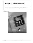
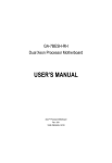
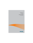
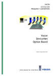
1
V A C O N
C X / C X L / C X S
F R E Q U E N C Y
C O N V E R T E R S
I/O-expander board
installation manual
( Va c o n C X / C X L - r a n g e )
Subject to changes without notice.
FOR SMOOTH CONTROL
Vacon
I/O-expander board installation (Vacon CX/CXL-range)
Page 1 (10)
CONTENTS
1 G E N E R A L ...........................................2
1.1 Vacon CX100OPT ....................... 2
1.2 Vacon CX101OPT ....................... 2
1.3 Vacon CX102OPT ....................... 2
1.4 Vacon CX103OPT ....................... 2
1.5 Vacon fieldbus boards .................. 3
2 S P E C I F I C AT I O N S ...............................3
3 INSTALLATION ...................................4
3.1 General ...................................... 4
3.2 Installation................................... 5
4 CONTROL CONNECTIONS ..............7
4.1 Vacon CX 100OPT ...................... 7
4.2 Vacon CX 101OPT ....................... 8
4.3 Vacon CX 102OPT ....................... 9
4.4 Vacon CX 103OPT ..................... 10
Vacon Plc
Phone:
Service:
+358-201 2121
+358-40-8371 150
Fax:
+358-201 212 205
E-mail: [email protected]
http://www.vacon.com
Page 2 (10)
I/O-expander board installation (Vacon CX/CXL-range)
1
GENERAL
1.1
Vacon CX100OPT
Vacon
The available I/O can be increased by using the Vacon CX100OPT I/O-expander
board:
-
5 digital inputs (standard signals)
2 analogue inputs (standard signals)
3 relay outputs (standard signals)
analogue output (programmable in "Five in One+" Application)
thermistor input (can be directly connected to the motor thermistors to
monitor the motor temperature)
- encoder input
Typical use: Closed Loop Vector Control
1.2
Vacon CX101OPT
The available I/O can be increased by using the Vacon CX101OPT I/O-expander
board:
- 5 digital inputs (standard signals)
- relay output (standard signal)
- thermistor input (can be directly connected to the motor thermistors to monitor
the motor temperature)
Typical use: thermistor input required
1.3
Vacon CX102OPT
The available I/O can be increased by using the Vacon CX102OPT I/O-expander
board:
-
5 digital inputs (standard signals)
2 analogue inputs (standard signals)
3 relay outputs (standard signals)
analogue output (programmable in "Five in One+" Application)
thermistor input (can be directly connected to the motor thermistors to
monitor the motor temperature)
- encoder input
Typical use: Closed Loop Vector Control
1.4
Vacon CX103OPT
The available I/O can be increased by using the Vacon CX103OPT I/O-expander
board:
-
5 digital inputs (standard signals)
3 relay outputs (standard signals)
analogue output (programmable in "Five in One+" Application)
thermistor input (can be directly connected to the motor thermistors to monitor
the motor temperature)
Typical use: thermistor input and additional analogue output required
Vacon Plc
Phone:
Service:
+358-201 2121
+358-40-8371 150
Fax:
+358-201 212 205
E-mail: [email protected]
http://www.vacon.com
I/O-expander board installation (Vacon CX/CXL-range)
Vacon
1.5
Page 3 (10)
Vacon fieldbus boards
Vacon fieldbus boards can be installed in the CX/CXL range frequency converters
like the I/O-expander boards, except the LonWorks board. The needed information
to install/commission fieldbus boards can be found in the respective fieldbus manual.
-
Vacon
Vacon
Vacon
Vacon
CX
CX
CX
CX
200OPT
201OPT
202OPT
203OPT
(Interbus-S)
(Modbus)
(Profibus-DP)
(LonWorks)
The LonWorks fieldbus board (Vacon CX 203OPT) must be installed in a separate
external option board box. More information can be found in the I/O-expander board
installation manual for CXS range.
2
S P E C I F I C AT I O N S
Safety
Fulfills EN50178, C-UL and EN60204-1 standards
Control
Analogue voltage, input
0—± 10 V, Ri ≥ 200 kΩ
connections
Analogue current, input
0(4)—20 mA, Ri = 250 Ω
Digital input
24 V: "0" ≤10 V, "1" ≥18 V, Ri > 5 kΩ
Aux. voltage
24 V (±20%), max. 50 mA
Reference voltage
10 V ±3 %, max. 10 mA
Analogue current, output 0(4)—20 mA, RL = 500 Ω , resolution 10 bit, accuracy ≤±2%
Analogue voltage, output 0(2)—10 V, RL ≥ 1 kΩ , resolution 10 bit, accuracy ≤±2%
Relay output
Max. switching voltage:
Max. switching load:
Max. continuous load:
300 V DC, 250 V AC
8A / 24 V DC
0,4 A / 300 V DC
2 kVA / 250 V AC
2 A rms
Thermistor input
Rtrip = 4.7 kΩ
Encoder input
24 V: "0" ≤10 V, "1" ≥18 V, Ri = 2.2 kΩ
5 V: "0" ≤ 2 V, "1" ≥ 3 V, Ri = 330 Ω
Table 2-1 Specifications.
(All the control connections are not found on every I/O-expander board, for more specific
information see Chapters 1 and 4.)
The control connections are isolated from the mains potential and the I/O ground is
connected to the frame of the inverter via a 1-MΩ resistor and 4,7-nF capacitor*). The
control I/O ground can be connected directly to the frame of the inverter by changing
the position of jumper X4 (GND ON/OFF) to ON-position. Digital inputs and relay
outputs are also isolated from the I/O ground.
*) Default value (X4 is GND OFF- position).
NOTE!
Internal components and circuit boards (except for the isolated I/O terminals) are at mains potential when the frequency converter is connected to
the mains. This voltage is extremely dangerous and may cause death or
severe injury if you come in contact with it.
The control I/O terminals are isolated from the mains potential, but the relay
outputs and other I/O's may have a dangerous voltage connected even if
the power is disconnected from the frequency converter.
Vacon Plc
Phone:
Service:
+358-201 2121
+358-40-8371 150
Fax:
+358-201 212 205
E-mail: [email protected]
http://www.vacon.com
Page 4 (10)
I/O-expander board installation (Vacon CX/CXL-range)
3
INSTALLATION
3.1.
General
Vacon
Check that your have received all the required parts (figure 3-1):
- I/O-expander board (1) (check that the typecode corresponds to your
order)
- protection foil (2)
- power cable (3) (4-pole)
- data cable (4) (10-pole)
- 20-pole I/O-wire (grey wire) (6)
- 2 to 8 black wires depending on I/O-expander board and application (7)
- terminal strips: 2 times 4-pole, 2 times 12-pole and 2 gable ends (8)
- stickers for I/O-terminal, I/O-board and I/O-expander board (8)
- screw (5) (for earthing), cable ties (9)
Note: The I/O-expander board package includes parts 1 - 5 for the power sizes
Vacon 2.2 CX_ /CXL_ - Vacon 90 CX_/CXL_.
For the bigger power sizes the parts 6 - 9 need to be ordered separately (type
code MOCXM8M12KIT).
6
1
3
5
2
7
8
4
9
osat_bw.tif
Figure 3-1. I/O-expander board parts.
If the delivery does not match your order, please contact your supplier immediately.
Before doing any commissioning carefully read the safety instructions in "USER'S
MANUAL VACON CX/CXL/CXS Frequency converters", Chapter 1, SAFETY.
Disconnect the frequency converter from the mains. NOTE: also the control circuits!
Wait further 5 minutes before opening the cover of the frequency converter. Verify
by measuring that the frequency converter is safe to touch.
Vacon Plc
Phone:
Service:
+358-201 2121
+358-40-8371 150
Fax:
+358-201 212 205
E-mail: [email protected]
http://www.vacon.com
Vacon
3.2
I/O-expander board installation (Vacon CX/CXL-range)
Page 5 (10)
INSTALLATION
The I/O-expander board should be installed above the existing control board location inside the frequency converter (see table 3-2) as described below:
1
Remove the control panel, control panel base (4 screws) and the jumper X4 from the
control board.
X4
figure3bw.tif
figure2bw.tif
2
3
Connect the power cable (3) to control board terminal X5. (The power cable can also be
connected to terminal X6 terminal, if the power cable from the power board is connected to
terminal X5.)
Connect the data cable (4) to control board
terminal X14. Bend the data cable into an
"S-curve" as far as possible from the power
board.
X5
X14
3
4
figure4bw.tif
4
Remove the protection foil (2) of the plastic
board and mount the plastic board above
the control board. Make sure that the plastic
board is correctly placed.
1
2
4
figure5bw.tif
5
Mount the I/O-expander board on the plastic board by the larger holes and "push" it into
the right position in the narrow position of the holes. Check that the I/O-expander board is
installed correctly. If you have difficulties mounting the plastic board and I/O-expander
board, slightly bend the regulator A4 and capacitor C59 of the control board.
6
Connect the power cable to I/O-expander
board terminal X2 and data cable to terminal X14.
X2
X14
figure6bw.tif
7
Install the jumper removed from terminal X4 of the control board on terminal X9 of the I/Oexpander board. Note: the jumper can be connected in ON or OFF position, see Vacon CX/
CXL/CXS User's Manual, Chapter 6.2.2. Tighten up the earthing screw (5).
X9
5
figure7bw.tif
Table 3-2.
Vacon Plc
figure8bw.tif
I/O-expander board installation (continues ...).
Phone:
Service:
+358-201 2121
+358-40-8371 150
Fax:
+358-201 212 205
E-mail: [email protected]
http://www.vacon.com
Page 6 (10)
8
9
I/O-expander board installation (Vacon CX/CXL-range)
Mount the terminal strip (8) on the
same bus bar as the control strip
according to the figure on the right.
Tighten the strip into the correct position using the gable ends.
Glue the I/O-terminal, I/O-EXPANDER
BOARD and I/O-CONTROL BOARD
stickers (8) on the base of the terminal
strip.
Vacon
9
6
7
8
8
rivil1bw.tif
10
Connect the grey I/O-wires (6) from the I/O-board terminals 201-220 to the corresponding
terminals of the terminal strip. Note: Also connect the control cable shield.
11
Connect the separate wires (7) (2-8 pieces depending on application) from I/O-expander
board terminals 221-228 to the corresponding terminals of the terminal strip.
Bind the I/O-cable and separate wires together with the cable ties (9). Tie the bunch to the
control cable.
12
Place the control panel and connect the
necessary control signals.
If an encoder input (closed loop control)
is to be used and the encoder works at a
5V level, move three jumpers from terminal
X5 to terminal X8. If the encoder works at
24V, then X8-terminal can be left free.
X8
X8b.tif
13
Check the connections and make sure that there are no foreign objects inside the frequency converter.
Before connecting the mains make sure that the cover of the frequency converter is closed.
14
Table 3-2.
Vacon Plc
Set the parameters of I/O-expander board according to the "Five in One+" -Applications
manual (parameter group 3)
I/O-expander board installation.
Phone:
Service:
+358-201 2121
+358-40-8371 150
Fax:
+358-201 212 205
E-mail: [email protected]
http://www.vacon.com
Vacon
I/O-expander board installation (Vacon CX/CXL-range)
4
CONTROL
4.1
Vacon CX100OPT
Encoder
Signal from
motor thermistors
*)
Page 7 (10)
CONNECTIONS
Terminal
Signal
Description
201
+10Vref
Reference output
Voltage for a potentiometer, etc.
202
Uin+
Analogue input, voltage
range 0—10 V DC
Not in use
203
GND
I/O ground
Ground for reference and controls
204
Iin+
Analogue input, current
Not in use
205
I in-
range 0—20 mA
206
+24V
Control voltage output
Voltage for switches, etc. max. 50 mA
207
GND
I/O ground
Ground for reference and controls
208
CMC
Common for DIC1-DIC5
Connect to GND or + 24 V
209
DIC1
External fault
(closing contact)
Contact open = no fault
Contact closed = fault
210
DIC2
Run disable
Cont. open = start of motor enabled
Cont. closed= start of motor disabled
211
DIC3
Acceler. / Decel. time
selection
Contact open = time 1 selected
Contact closed = time 2 selected
212
DIC4
Jogging speed selection
Contact open = no action
Contact closed = jogging speed
213
DIC5
Fault reset
Contact open = no action
Contact closed = fault reset
214
DI6A+
Pulse input A
215
DI6A-
(differential input)
216
217
DI7B+
DI7B-
Pulse input B
(differential input)
90 degrees phase shift compared
to pulse input A
218
219
DI8Z+
DI8Z-
Pulse input C
(differential input)
one pulse per one revolution
220
Iout+
Analogue output
0—20 mA/RL max. 500 Ω
Programmable
(Motor current as default value)
221
TI+
Thermistor input
222
TI-
223
RO3/1
224
RO3/2
225
RO4/1
226
RO4/2
227
RO5/1
228
RO5/2
Relay output 3
READY
Relay output 4
RUN
Relay output 5
FAULT
Figure 4-1 Control connections of Vacon CX100OPT.
*) NOTE! Thermistor input (terminals 221 and 222) must be shorted if not used.
Vacon Plc
Phone:
Service:
+358-201 2121
+358-40-8371 150
Fax:
+358-201 212 205
E-mail: [email protected]
http://www.vacon.com
Page 8 (10)
4.2
I/O-expander board installation (Vacon CX/CXL-range)
Vacon CX101OPT
Signal from
motor thermistors
*)
Terminal
Signal
Description
206
+24V
Control voltage output
Voltage for switches, etc. max. 50 mA
207
GND
I/O ground
Ground for reference and controls
208
CMC
Common for DIC1-DIC5
Connect to GND or + 24 V
209
DIC1
External fault
(closing contact)
Contact open = no fault
Contact closed = fault
210
DIC2
Run disable
Cont. open = start of motor enabled
Cont. closed= start of motor disabled
211
DIC3
Acceler. / Decel. time
selection
Contact open = time 1 selected
Contact closed = time 2 selected
212
DIC4
Jogging speed selection
Contact open = no action
Contact closed = jogging speed
213
DIC5
Fault reset
Contact open = no action
Contact closed = fault reset
214
N.C.
Not connected
215
N.C.
Not connected
221
TI+
222
TI+
225
RO4/1
226
RO4/2
Thermistor input
Relay output 4
RUN
Figure 4-2 Control connections of Vacon CX101OPT.
*) NOTE! Thermistor input (terminals 221 and 222) must be shorted if not used.
Vacon Plc
Vacon
Phone:
Service:
+358-201 2121
+358-40-8371 150
Fax:
+358-201 212 205
E-mail: [email protected]
http://www.vacon.com
Vacon
4.3
I/O-expander board installation (Vacon CX/CXL-range)
Page 9 (10)
Vacon CX102OPT
Encoder
Signal from
motor thermistors
*)
Terminal
Signal
Description
201
+10Vref
Reference output
Voltage for a potentiometer, etc.
202
Uin+
Analogue input, voltage
range 0—10 V DC
Not in use
203
GND
I/O ground
Ground for reference and controls
204
Uin+
Analogue input, voltage
Not in use
205
U in -
range 0—10 V DC
206
+24V
Control voltage output
Voltage for switches, etc. max. 50 mA
207
GND
I/O ground
Ground for reference and controls
208
CMC
Common for DIC1-DIC5
Connect to GND or + 24 V
209
DIC1
External fault
(closing contact)
Contact open = no fault
Contact closed = fault
210
DIC2
Run disable
Cont. open = start of motor enabled
Cont. closed= start of motor disabled
211
DIC3
Acceler. / Decel. time
selection
Contact open = time 1 selected
Contact closed = time 2 selected
212
DIC4
Jogging speed selection
Contact open = no action
Contact closed = jogging speed
213
DIC5
Fault reset
Contact open = no action
Contact closed = fault reset
214
DI6A+
Pulse input A
215
DI6A-
(differential input)
216
217
DI7B+
DI7B-
Pulse input B
(differential input)
218
DO1
Encoder direction output
219
DO2
Encoder divider 1/64 output
220
U out+
Analogue output
0—10 V DC/RL ≥ 1 kΩ
221
TI+
Thermistor input
222
TI-
223
RO3/1
224
RO3/2
225
RO4/1
226
RO4/2
227
RO5/1
228
RO5/2
90 degrees phase shift compared
to pulse input A
Programmable
(Motor voltage as default value)
Relay output 3
READY
Relay output 4
RUN
Relay output 5
FAULT
Figure 4-3 Control connections of Vacon CX102OPT.
*) NOTE! Thermistor input (terminals 221 and 222) must be shorted if not used.
Vacon Plc
Phone:
Service:
+358-201 2121
+358-40-8371 150
Fax:
+358-201 212 205
E-mail: [email protected]
http://www.vacon.com
Page 10 (10) I/O-expander board installation (Vacon CX/CXL-range)
4.4
Vacon CX103OPT
Signal from
motor thermistors
*)
Terminal
Signal
Description
206
+24V
Control voltage output
Voltage for switches, etc. max. 50 mA
207
GND
I/O ground
Ground for reference and controls
208
CMC
Common for DIC1-DIC5
Connect to GND or + 24 V
209
DIC1
External fault
(closing contact)
Contact open = no fault
Contact closed = fault
210
DIC2
Run disable
Cont.open = start of motor enabled
Cont. closed= start of motor disabled
211
DIC3
Acceler. / Decel. time
selection
Contact open = time 1 selected
Contact closed = time 2 selected
212
DIC4
Jogging speed selection
Contact open = no action
Contact closed = jogging speed
213
DIC5
Fault reset
Contact open = no action
Contact closed = fault reset
214
GND
I/O ground
215
I out+
Analogue output
0—20 mA/RL max. 500 Ω
221
TI+
Thermistor input
222
TI-
223
RO3/1
224
RO3/2
225
RO4/1
226
RO4/2
227
RO5/1
228
RO5/2
Programmable
(Motor current as default value)
Relay output 3
READY
Relay output 4
RUN
Relay output 5
FAULT
Figure 4-3 Control connections of Vacon CX103OPT.
*) NOTE! Thermistor input (terminals 221 and 222) must be shorted if not used.
Vacon Plc
Vacon
Phone:
Service:
+358-201 2121
+358-40-8371 150
Fax:
+358-201 212 205
E-mail: [email protected]
http://www.vacon.com
UD 00085G, 18.10.2000
VACON PLC
P.O. Box 25
Runsorintie 5
FIN-65381 VAASA
FINLAND
Phone: +358-201 2121
Distributor:
Fax: +358-201 212 205
Service: +358-40-8371 150
E-mail: [email protected]
http://www.vacon.com