1
MELSECNET, MELSECNET/B Local Station Data
Link Module User's Manual
-A1SJ71AP23Q
-A1SJ71AR23Q
-A1SJ71AT23BQ
SAFETY PRECAUTIONS
(Always read these instructions before using this product)
Before using this product, please read this manual and the relevant manuals introduced in this manual
carefully and pay full attention to safety to handle the product correctly.
The precautions given in this manual are concerned with this product only. For the safety precautions of the
programmable controller system, please read the User's Manual for the CPU module used.
In this manual, the safety precautions are classified into two levels: "
WARNING" and "
CAUTION".
WARNING
Indicates that incorrect handling may cause hazardous conditions,
resulting in death or severe injury.
CAUTION
Indicates that incorrect handling may cause hazardous conditions,
resulting in minor or moderate injury or property damage.
Note that the
CAUTION level may lead to a serious consequence according to the circumstances.
Observe the precautions of both levels because they are important for personal and system safety.
Please save this manual to make it accessible when required and always forward it to the end user.
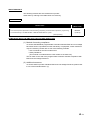
[DESIGN PRECAUTIONS]
WARNING
● For each station's operating status in the case of a communication error in the network, refer to this
manual.
A malfunction due to a communication error may result in an accident.
● To control a running programmable controller (data modification) by connecting GX Developer to a
CPU module or connecting a personal computer to an intelligent function module (special function
module), create an interlock circuit on the sequence program so that the entire system will function
safely all the time.
Also, before performing any other controls (e.g. program modification, operating status change
(status control)) to the programmable controller, read the manual carefully and ensure the safety.
Especially, in the case of controlling a remotely-located programmable controller from an external
device, a programmable controller side problem could not be resolved immediately due to data
communication failure.
To prevent this, establish corrective procedures for communication failure between the external
device and the programmable controller CPU, as well as creating an interlock circuit on the program.
CAUTION
● Do not install the control lines and/or communication cables together with the main circuit or power
cables, and also do not bring them close to each other.
Keep a distance of 100mm (3.94 inch) or more between them. Failure to do so may cause a
malfunction due to noise.
A-1
[INSTALLATION PRECAUTIONS]
CAUTION
● Use the programmable controller in the environment conditions given in the general specifications of
the User's Manual for the CPU module used.
Failure to do so may cause an electric shock, fire, malfunction, or damage to or deterioration of the
product.
● Insert the module fixing projection into the module fixing hole in the base unit to mount the
module.(For the AnS series module, fix it to the base unit with screws within the specified torque.)
Incorrect module mounting may cause a malfunction, failure, or drop of the module.
● Be sure to shut off all phases of the external power supply used by the system before mounting or
removing the module.
Failure to do so may damage the module.
● Do not directly touch any conductive part or electronic component of the module.
Doing so may cause a malfunction or failure of the module.
[WIRING PRECAUTIONS]
WARNING
● Be sure to shut off all phases of the external power supply before installation or wiring.
Failure to do so may result in an electric shock or damage to the product.
CAUTION
● Properly solder a connector for coaxial cable.
Failure to do so may cause malfunction.
● Be careful to prevent foreign matter such as dust or wire chips from entering the module.
Failure to do so may cause a fire, failure or malfunction.
● Be sure to place the communication cables or power cables in a duct or clamp them.
If not, dangling cables may swing or inadvertently be pulled, resulting in damage to the module or
cables, or malfunctions due to poor cable contact.
A-2
[WIRING PRECAUTIONS]
CAUTION
● When disconnecting a communication cable or power cable, do not pull it by holding the cable part.
To disconnect the cable, hold its connector that is plugged into the module.
Loosen screws for a terminal block before disconnecting a cable for connecting terminal block.
Pulling the cable part with the cable still connected to the module may damage the module and/or
cable, or cause malfunctions due to poor cable contact.
[START-UP AND MAINTENANCE PRECAUTIONS]
CAUTION
● Do not disassemble or remodel each of the modules.
Doing so may cause failure, malfunctions, personal injuries and/or a fire.
● When using a wireless communication device such as a mobile phone, keep a distance of 25cm
(9.85 inch) or more from the programmable controller in all directions.
Failure to do so may cause malfunctions.
● Be sure to shut off all phases of the external power supply used by the system before mounting or
removing the module.
Not doing so may damage the product.
● Do not touch terminals during power-on.
Doing so may cause malfunctions.
● Be sure to shut off all phases of the external power supply used by the system before cleaning or
retightening the terminal screw or module mounting screw.
Not doing so may cause a failure or malfunction of the module.
If the screw is too loose, it may cause a drop, short circuit or malfunction.
Excessive tightening may cause damage to the screw and/or module, resulting in a drop, short
circuit or malfunction.
● Before handling the module, touch a grounded metal object to discharge the static electricity from
the human body.
Not doing so may cause a failure or malfunction of the module.
[DISPOSAL PRECAUTIONS]
CAUTION
● When disposing of the product, treat it as industrial waste.
A-3
CONDITIONS OF USE FOR THE PRODUCT
(1) Mitsubishi programmable controller ("the PRODUCT") shall be used in conditions;
i) where any problem, fault or failure occurring in the PRODUCT, if any, shall not lead to any major
or serious accident; and
ii) where the backup and fail-safe function are systematically or automatically provided outside of
the PRODUCT for the case of any problem, fault or failure occurring in the PRODUCT.
(2) The PRODUCT has been designed and manufactured for the purpose of being used in general
industries.
MITSUBISHI SHALL HAVE NO RESPONSIBILITY OR LIABILITY (INCLUDING, BUT NOT
LIMITED TO ANY AND ALL RESPONSIBILITY OR LIABILITY BASED ON CONTRACT,
WARRANTY, TORT, PRODUCT LIABILITY) FOR ANY INJURY OR DEATH TO PERSONS OR
LOSS OR DAMAGE TO PROPERTY CAUSED BY the PRODUCT THAT ARE OPERATED OR
USED IN APPLICATION NOT INTENDED OR EXCLUDED BY INSTRUCTIONS, PRECAUTIONS,
OR WARNING CONTAINED IN MITSUBISHI'S USER, INSTRUCTION AND/OR SAFETY
MANUALS, TECHNICAL BULLETINS AND GUIDELINES FOR the PRODUCT.
("Prohibited Application")
Prohibited Applications include, but not limited to, the use of the PRODUCT in;
• Nuclear Power Plants and any other power plants operated by Power companies, and/or any
other cases in which the public could be affected if any problem or fault occurs in the PRODUCT.
• Railway companies or Public service purposes, and/or any other cases in which establishment of
a special quality assurance system is required by the Purchaser or End User.
• Aircraft or Aerospace, Medical applications, Train equipment, transport equipment such as
Elevator and Escalator, Incineration and Fuel devices, Vehicles, Manned transportation,
Equipment for Recreation and Amusement, and Safety devices, handling of Nuclear or
Hazardous Materials or Chemicals, Mining and Drilling, and/or other applications where there is a
significant risk of injury to the public or property.
Notwithstanding the above, restrictions Mitsubishi may in its sole discretion, authorize use of the
PRODUCT in one or more of the Prohibited Applications, provided that the usage of the PRODUCT
is limited only for the specific applications agreed to by Mitsubishi and provided further that no
special quality assurance or fail-safe, redundant or other safety features which exceed the general
specifications of the PRODUCTs are required. For details, please contact the Mitsubishi
representative in your region.
A-4
REVISIONS
*The manual number is given on the bottom left of the cover.
Print Date
*Manual Number
Revision
Mar., 2007
SH(NA)-080670ENG-A First edition
Oct., 2007
SH(NA)-080670ENG-B
Correction
Section 2.2, 3.1
Aug., 2010
SH(NA)-080670ENG-C
Correction
SAFETY PRECAUTIONS, Section 2.2, 3.2.1, 3.2.2, 3.4.2, 7.2, Appendix 4.2,
WARRANTY
Addition
CONDITIONS OF USE FOR THE PRODUCT
Apr., 2011
SH(NA)-080670ENG-D
Oct., 2011
SH(NA)-080670ENG-E
Correction
Section 3.6.4, 3.6.5, 7.2, 8.1.2, Appendix 4.2
Correction
SAFETY PRECAUTIONS, COMPLIANCE WITH THE EMC AND LOW
VOLTAGE DIRECTIVES, GENERIC TERMS AND ABBRERVIATIONS,
Chapter 1, Section 1.1, 2.2
Dec., 2014
SH(NA)-080670ENG-F
Correction
COMPLIANCE WITH THE EMC AND LOW VOLTAGE DIRECTIVES, HOW TO
READ THIS MANUAL, Chapter 1, Section 1.1, 2.2, Chapter 3, Section 5.1, 5.3,
6.2.1, 7.2, 8.1.4, Appendix 4.2
Addition
Appendix 3
Japanese Manual Version SH-080669-G
This manual confers no industrial property rights or any rights of any other kind, nor does it confer any patent licenses.
Mitsubishi Electric Corporation cannot be held responsible for any problems involving industrial property rights which may
occur as a result of using the contents noted in this manual.
2007 MITSUBISHI ELECTRIC CORPORATION
A-5
INTRODUCTION
Thank you for choosing the Mitsubishi MELSEC-AnS Series of General Purpose Programmable
Controllers.
Before using the equipment, please read this manual carefully to develop full familiarity with the functions
and performance of the AnS series programmable controller you have purchased, so as to ensure correct
use.
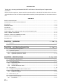
CONTENTS
SAFETY PRECAUTIONS .................................................................................................................................A - 1
CONDITIONS OF USE FOR THE PRODUCT..................................................................................................A - 4
REVISIONS.......................................................................................................................................................A - 5
INTRODUCTION...............................................................................................................................................A - 6
CONTENTS ......................................................................................................................................................A - 6
ABOUT MANUALS ...........................................................................................................................................A - 9
COMPLIANCE WITH THE EMC AND LOW VOLTAGE DIRECTIVES.............................................................A - 9
HOW TO READ THIS MANUAL .....................................................................................................................A - 10
GENERIC TERMS AND ABBRERVIATIONS .................................................................................................A - 11
DEFINITIONS OF TERMINOLOGY................................................................................................................A - 12
PACKING LIST ...............................................................................................................................................A - 13
CHAPTER1 OVERVIEW
1.1
1 - 1 to 1 - 5
Features........................................................................................................................................... 1 - 2
CHAPTER2 SYSTEM CONFIGURATION
2 - 1 to 2 - 5
2.1
Overall System Configuration .......................................................................................................... 2 - 1
2.2
Applicable Systems ......................................................................................................................... 2 - 4
2.2.1
2.2.2
Applicable system for Q series ................................................................................................. 2 - 4
Applicable system for L series .................................................................................................. 2 - 5
CHAPTER3 SPECIFICATIONS
3 - 1 to 3 - 29
3.1
Performance Specifications ............................................................................................................. 3 - 1
3.2
Cable Specifications ........................................................................................................................ 3 - 5
3.2.1
3.2.2
3.2.3
Optical fiber cable ..................................................................................................................... 3 - 5
Coaxial cable ............................................................................................................................ 3 - 6
Shielded twisted pair cable ....................................................................................................... 3 - 9
3.3
Function List .................................................................................................................................. 3 - 10
3.4
I/O Signal for Programmable Controller CPU ................................................................................ 3 - 11
3.4.1
3.4.2
List of I/O signal ...................................................................................................................... 3 - 11
Details of I/O signal................................................................................................................. 3 - 13
3.5
Buffer Memory List......................................................................................................................... 3 - 15
3.6
Details of Buffer Memory ............................................................................................................... 3 - 17
3.6.1
A-6
Precautions............................................................................................................................. 3 - 17
3.6.2
3.6.3
3.6.4
3.6.5
3.6.6
3.6.7
3.6.8
3.6.9
3.6.10
Presence or absence of refresh information table.................................................................. 3 - 18
Refresh information table ....................................................................................................... 3 - 19
LRDP instruction receive request/receive result/work area .................................................... 3 - 22
LWTP instruction receive request/receive result/work area ................................................... 3 - 24
Special relay (for link) (M9200 to M9255)............................................................................... 3 - 26
Special register (for link) (D9200 to D9255) ........................................................................... 3 - 26
Input (X0 to X7FF) and output (Y0 to Y7FF) .......................................................................... 3 - 27
Link relay (B0 to BFFF) .......................................................................................................... 3 - 28
Link register (W0 to WFFF) .................................................................................................... 3 - 29
CHAPTER4 FUNCTIONS
4.1
4 - 1 to 4 - 11
Cyclic Transmission Function .......................................................................................................... 4 - 1
4.1.1
4.1.2
1 : n communication (B/W communication) .............................................................................. 4 - 1
1 : 1 communication (X/Y communication) ............................................................................... 4 - 5
4.2
Transient Transmission Function..................................................................................................... 4 - 6
4.3
RAS Functions................................................................................................................................. 4 - 8
4.3.1
4.3.2
4.3.3
Automatic return function.......................................................................................................... 4 - 8
Loopback function .................................................................................................................... 4 - 9
Error detection function .......................................................................................................... 4 - 11
CHAPTER5 PREPARATORY PROCEDURES BEFORE OPERATION
5.1
5 - 1 to 5 - 21
Implementation and Installation ....................................................................................................... 5 - 1
5.1.1
Handling precautions................................................................................................................ 5 - 1
5.2
Preparatory Procedures before Operation....................................................................................... 5 - 2
5.3
Part Names and Settings................................................................................................................. 5 - 3
5.4
Wiring............................................................................................................................................... 5 - 7
5.4.1
5.4.2
5.4.3
5.5
Optical fiber cable..................................................................................................................... 5 - 7
Coaxial cable ............................................................................................................................ 5 - 9
Shielded twisted pair cable..................................................................................................... 5 - 11
Self-diagnostic Test ....................................................................................................................... 5 - 12
5.5.1
5.5.2
5.5.3
Self-loopback test ................................................................................................................... 5 - 13
Station-to-station test.............................................................................................................. 5 - 16
Forward loop test/reverse loop test ........................................................................................ 5 - 19
CHAPTER6 LINK DATA SEND/RECEIVE PROCESSING AND PROCESSING TIME
6 - 1 to 6 - 11
6.1
Link Data Send/Receive Processing ............................................................................................... 6 - 1
6.1.1
6.1.2
6.1.3
6.2
Send/receive processing overview ........................................................................................... 6 - 1
Link refresh timing .................................................................................................................... 6 - 2
Link data handling in the case of a communication error ......................................................... 6 - 3
Transmission Delay Time ................................................................................................................ 6 - 5
6.2.1
6.2.2
6.2.3
Transmission delay time........................................................................................................... 6 - 5
Link refresh time ....................................................................................................................... 6 - 7
Link data send/receive time (Link scan) ................................................................................... 6 - 8
A-7
CHAPTER7 PROGRAMMING
7 - 1 to 7 - 16
7.1
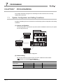
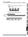
System Configuration and Setting Conditions ................................................................................. 7 - 1
7.2
Program for Refresh and for Receiving LRDP/LWTP Instruction .................................................... 7 - 3
CHAPTER8 TROUBLESHOOTING
8.1
8 - 1 to 8 - 15
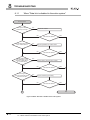
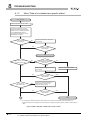
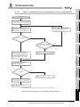
Troubleshooting Flowchart .............................................................................................................. 8 - 2
8.1.1
8.1.2
8.1.3
8.1.4
When "Data link is disabled in the entire system"..................................................................... 8 - 3
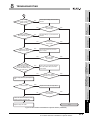
When "Data link is disabled at a specific station" ..................................................................... 8 - 5
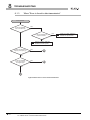
When "Error is found in data transmission" .............................................................................. 8 - 7
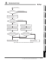
When "Communication error is detected in some slave stations" .......................................... 8 - 12
8.2
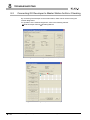
Connecting GX Developer to Master Station for Error Checking................................................... 8 - 13
8.3
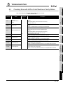
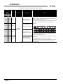
Checking Error with LEDs of Link Module on Faulty Station ......................................................... 8 - 14
8.4
Checking the Program for Refresh ................................................................................................ 8 - 15
APPENDICES
App - 1 to App - 25
Appendix 1
List of Special Relays (for Link) ........................................................................................App - 1
Appendix 2
List of Special Registers (for Link) ....................................................................................App - 3
Appendix 3
Steps to Create a Program for L Series ...........................................................................App - 5
Appendix 4
Replacing Local Station from A/QnA Series to Q Series ..................................................App - 9
Appendix 4.1
Differences between Q series and A/QnA series local stations ...............................App - 9
Appendix 4.2
When utilizing an existing project of the A/QnA series local station .......................App - 11
Appendix 5 Program for Refresh when Using Multiple Local Modules..............................................App - 13
Appendix 5.1
System configuration and setting conditions ..........................................................App - 14
Appendix 5.2
Program for refresh ................................................................................................App - 16
Appendix 6 External Dimensions.......................................................................................................App - 23
Appendix 6.1
Appendix 6.2
Appendix 6.3
INDEX
A-8
A1SJ71AP23Q .......................................................................................................App - 23
A1SJ71AR23Q .......................................................................................................App - 24
A1SJ71AT23BQ .....................................................................................................App - 25
Index - 1 to Index - 1
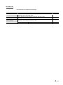
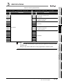
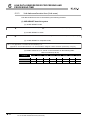
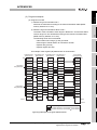
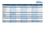
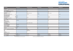
ABOUT MANUALS
The following manuals are also related to this product.
Order them by referring to the table below as necessary.
Related manual
Manual No.
Manual name
(Model code)
Type MELSECNET, MELSECNET/B Data Link System Reference Manual
This manual explains specifications, data link setting, preparatory procedures before operation, programming,
IB-66350
and troubleshooting of the MELSECNET or MELSECNET/B data link system.
(13JF70)
(Sold separately)
COMPLIANCE WITH THE EMC AND LOW VOLTAGE DIRECTIVES
(1) Method of ensuring compliance
To ensure that Mitsubishi programmable controllers maintain EMC and Low Voltage
Directives when incorporated into other machinery or equipment, certain measures
may be necessary. Please refer to one of the following manuals.
• User’s manual for the CPU module used
• Safety Guidelines
(This manual is included with the CPU module or the base unit.)
The CE mark on the side of the programmable controller indicates compliance with
EMC and Low Voltage Directives.
(2) Additional measures
To ensure that this product maintains EMC and Low Voltage Directives, please refer
to one of the manuals listed in (1).
A-9
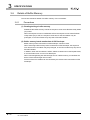
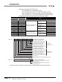
HOW TO READ THIS MANUAL
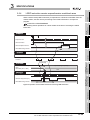
The following explains how to interpret the symbols for network station types that are used
in the text, tables, and figures.
(1) MELSECNET or MELSECNET/B data link system
Abbreviation of network type
Description
M station
L station
Master station for the second tier
Local station in the second tier
R station
L/m station
Remote I/O station in the second tier
Local station in the second tier/master station for the third tier
l station
r station
Local station in the third tier
Remote I/O station in the third tier
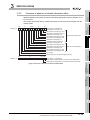
(2) MELSECNET/H network system
MP
Station No.
1 to 64
Abbreviation
MP: Control station, NS: Normal station
Network No.
1 to 239
(Example)
• Network No.1, control station, station No.1
1MP1
• Network No.1, normal station, station No.2
1NS2
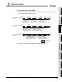
(3) When using this product in the system of L series
Where there is no difference between Q series and L series, the description is given
for Q series only; in reading this manual, substitute "Q" with "L" where appropriate.
Here are examples of how to substitute the character:
A - 10
Description in this manual (Q)
Q series
After substitution (L)
L series
QA1S5 B
LA1S5 B
QA1S6 B
QCPU
LA1S6 B
LCPU
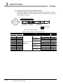
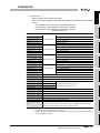
GENERIC TERMS AND ABBRERVIATIONS
This manual describes the MELSECNET or MELSECNET/B local station data link module
using the following generic terms and abbreviations, unless otherwise specified.
Generic term/
abbreviation
Description
Generic product name for SWnD5C-GPPW-E, SWnD5C-GPPW-EA, SWnD5C-GPPW-EV, and
GX Developer
SWnD5C-GPPW-EVA. ("n" means version 4 or later.)
"-A" and "-V" mean "volume license product" and "version-upgrade product" respectively.
GX Works2
MELSECNET
Generic product name of SWnDNC-GXW2-E ("n" represents the version.)
Abbreviation for the MELSECNET data link system
MELSECNET/B
MELSECNET/H
Abbreviation for the MELSECNET/B data link system
Abbreviation for the MELSECNET/H network system
MELSECNET (II)
Generic term for the MELSECNET or MELSECNET/B data link system
Abbreviation for the A1SJ71AP23Q or A1SJ71AR23Q type MELSECNET local station data link
Local module
Link module
module and the A1SJ71AT23BQ type MELSECNET/B local station data link module
Abbreviation for the MELSECNET or MELSECNET/B data link module
QA1S5 B
Another term for the QA1S51B extension base unit
QA1S6 B
Generic term for the QA1S65B and QA1S68B extension base units
A - 11
DEFINITIONS OF TERMINOLOGY
The following explains definitions of the terms used in this manual.
Term
RAS
Description
Abbreviation for Reliability, Availability, and Serviceability.
This term is used to express the overall usability of automation systems.
Station that controls slave stations (local station and remote I/O station) connected to the data
link system.
Master station
It sets the link parameter for the data link system.
One master station is required per data link system.
The station No. of the master station is set to "00".
Station that controls the I/O module or intelligent function module (special function module) of
Local station
the host station in the program of the host station, incorporating link data (B, W, X) of the data
link system.
Remote I/O station
A - 12
Station that controls the I/O module or special function module of the host station in the
program of the master station.
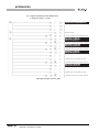
PACKING LIST
The followings are included in the package.
Model
A1SJ71AP23Q
A1SJ71AR23Q
Product name
A1SJ71AP23Q type MELSECNET local station data link module
(Applicable cable: optical fiber cable)
A1SJ71AR23Q type MELSECNET local station data link module
(Applicable cable: coaxial cable)
A1SJ71AT23BQ type MELSECNET/B local station data link module
A1SJ71AT23BQ
(Applicable cable: shielded twisted pair cable)
Terminating resistor (110 , 1/2W)
Quantity
1
1
1
1
A - 13
1
OVERVIEW
CHAPTER1
OVERVIEW
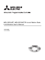
This manual describes the specification, function, preparatory procedures before
operation, programming, and troubleshooting of the following data link module (hereinafter
referred to as a local module).
• A1SJ71AP23Q type MELSECNET local station data link module
• A1SJ71AR23Q type MELSECNET local station data link module
• A1SJ71AT23BQ type MELSECNET/B local station data link module
When applying a program example introduced in this manual to the actual system, make
sure to examine the applicability and confirm that it will not cause system control
problems.
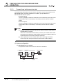
The local module can mount the Q series programmable controller as a local station in the
second tier or local station in the third tier of the MELSECNET or MELSECNET/B data link
system.
Mount the local module to the following base unit.
• QA1S5 B extension base unit
• QA1S6 B extension base unit
Master station
Q series programmable controller
(Main base unit)
Q series local station
Local station
MELSECNET (II)
(QA1S5
QA1S6
B extension base unit or
B extension base unit)
Local module
Local station
Figure 1.1 MELSECNET or MELSECNET/B data link system
POINT
(1) This manual describes necessary information to add or replace a Q series
local station in the MELSECNET or MELSECNET/B data link system.
For the details of the MELSECNET or MELSECNET/B data link system, refer
to the following manual.
Type MELSECNET, MELSECNET/B Data Link System Reference
Manual.
(2) Where there is no difference between Q series and L series, the description is
given for Q series only; substitute "Q" with "L" where appropriate.
1-1
1
OVERVIEW
Features
This section describes features of a local module.
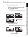
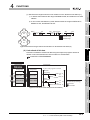
(1) Cyclic transmission function
(a) 1: n communication (B/W communication)
Data is communicated between the master station and a local station and
between local stations.
In this communication, ON/OFF information and 16-bit data are communicated.
1) The ON/OFF information is communicated by link relays (B).
3
SPECIFICATIONS
2) The 16-bit data is communicated by link registers (W).
Q series local station
Local module
CPU module
Buffer memory
Link data
storage area
Link data
storage area
Data memory
storage area
B
B
B
B
W
W
W
W
4
FUNCTIONS
Data memory
storage area
Local station
Link data
storage area
B
B
W
W
PREPARATORY
PROCEDURES BEFORE
OPERATION
Data memory
storage area
5
Data flow (Send/receive processing)
Link scan
Link refresh
Figure 1.2 B/W communication data flow
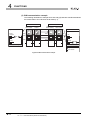
(b) 1:1 communication (X/Y communication)
The one-to-one data communication is performed between the master station and
a local station.
The ON/OFF information can be communicated using the input (X)/output (Y).
7
Q series local station
Master station
Local module
6
LINK DATA SEND/
RECEIVE PROCESSING
AND PROCESSING TIME
Master station
SYSTEM
CONFIGURATION
2
The data can be communicated between master and local stations cyclically.
CPU module
Buffer memory
Data memory
storage area
Link data
storage area
Link data
storage area
Data memory
storage area
X
X
Y
Y
Y
Y
X
X
PROGRAMMING
1.1
OVERVIEW
8
Data flow (Send/receive processing)
Link scan
TROUBLESHOOTING
1
Link refresh
Figure 1.3 X/Y communication data flow
1.1 Features
1-2
1
OVERVIEW
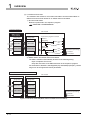
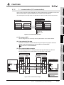
(c) Link refresh of link data
The method of link refresh for a Q series local station and the master station is
different from that of link refresh for an A/QnA series local station.
1) Q series local station
Refresh is performed in the sequence program.
CHAPTER 7 PROGRAMMING
Q series local station
Local module
CPU module
Buffer memory
Data memory
storage area
Link data
storage area
"A part" of the program for refresh
Receive
processing
400H
DMOV
W0 to WFF
W0 to WFF
BMOV
4FFH
500H
W100 to W1FF
W100 to W1FF
U0\
W0Z0 Z1
G1024Z0
Send
processing
DMOV
5FFH
U0\
Z0
G4
BMOV W0Z0
U0\
Z0
G2
Data flow
(Send/receive processing)
Link scan
U0\
Z1
G1024Z0
Link refresh
Figure 1.4 Link refresh of link data (Q series local station)
2) Master station and A/QnA series local station
The data is refreshed automatically at either of the following timing.
• Upon completion of link scan
• Only after execution of the END instruction in the sequence program
For the AnUCPU, QnACPU, A2US(H)CPU(S1) and Q2AS(H)CPU(S1), refresh
ranges can be changed with refresh parameters.
Master station and local station for A/QnA series
Link module
CPU module
Link data
storage area
Data memory
storage area
W0 to WFF
W0 to WFF
W100 to W1FF
W100 to W1FF
Data flow
(Send/receive processing)
Link scan
Link refresh
Figure 1.5 Link refresh of link data (Master station and A/QnA series local station)
1-3
1.1 Features
1
OVERVIEW
1
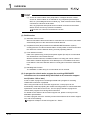
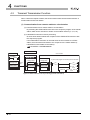
(a) Communication from a master station to a local station
By executing the LRDP/LWTP instruction in the sequence program of the master
station, data can be read from or written to local station devices (T, C, D, W).
1) Q series local station
The receive processing is performed to the LRDP/LWTP instruction in a
sequence program.
CHAPTER 7 PROGRAMMING
SPECIFICATIONS
3
Buffer memory
LWTP
Link data
storage area
Device
write
D20 to D29
DCH
Data memory
storage area
"A part" of the program for receiving LWTP instruction
= K4
Write data
D200 to D209
U0\
G174
DMOV
MOV
= H4420 Z0
BMOV
U0\
Z0
G216
U0\
Z2
G219
U0\
D0Z1 Z2
G220
4
5
Figure 1.6 LWTP instruction receive processing (Q series local station)
2) A/QnA series local station
The receive processing is performed to the LRDP/LWTP instruction in the
system.
(The program for receiving LRDP/LWTP instruction is not required.)
PREPARATORY
PROCEDURES BEFORE
OPERATION
Command
Data memory
storage area
CPU module
Local module
FUNCTIONS
Q series local station
Master station
2
SYSTEM
CONFIGURATION
(b) LRDP/LWTP instruction receive processing
A Q series local station and an A/QnA series local station are different in
processing at the time of accepting the LRDP/LWTP instruction.
OVERVIEW
(2) Transient transmission function
LINK DATA SEND/
RECEIVE PROCESSING
AND PROCESSING TIME
6
A/QnA series local station
Master station
CPU module
Link module
Command
LWTP
D200 to D209
PROGRAMMING
D20 to D29
7
Device
write
Figure 1.7 LWTP instruction receive processing (A/QnA series local station)
8
TROUBLESHOOTING
Data memory
storage area
Data memory
storage area
1.1 Features
1-4
1
OVERVIEW
POINT
(1) Access to another station from peripherals or intelligent function module
Access to another station is not allowed for any peripheral (GX Developer,
GOT, etc.) and intelligent function module (e.g. serial communication module)
connected to a Q series local station.
Also, any peripheral and special function module connected to the master
station cannot access any Q series local station.
Section 4.2 Transient Transmission Function
(3) RAS function
(a) Automatic return function
When a local station disconnected due to a data link error is recovered, the station
automatically returns to the network and restarts data link.
(b) Loopback function (Not provided for the MELSECNET/B data link system)
A faulty part such as a disconnected cable or a faulty station is disconnected from
the network to continue data link among normally operating stations.
(c) Error detection function
Data of the special relay (for link) and special register (for link) of a local module
are refreshed into CPU module devices.
With the refreshed devices, the data link status or a faulty part can be checked.
Note that the network diagnostics of GX Developer is not available for Q series
local stations. Check the data link status or a faulty part in the above-mentioned
way.
(d) Self-diagnostic function
The hardware or cable wiring of a local module can be checked.
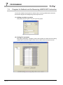
(4) A program for refresh and a program for receiving LRDP/LWTP
instruction can be created easily with A/QnA to Q conversion support
tool (Version 1.02 or later)
A tool to create a program for refreshing link data and a program for receiving
LRDP/LWTP instruction is prepared.
When using the A/QnA to Q conversion support tool, a new project can be
automatically created by inputting the module mounting position or refresh destination
specification of link data on the screen. The new project includes a program for
refresh and a program for receiving LWTP instruction.
For details on the A/QnA to Q conversion support tool, please consult your local
Mitsubishi representative.
To create a program used for L series by means of the A/QnA to Q conversion support
tool, refer to the following:
Appendix 3 Steps to Create a Program for L Series
1-5
1.1 Features
SYSTEM CONFIGURATION
1
OVERVIEW
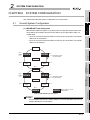
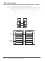
SYSTEM CONFIGURATION
This chapter describes the system configuration of a local module.
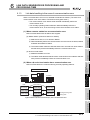
(1) MELSECNET data link system
MELSECNET data link system is a system which connects the master station and
slave stations (local station and remote I/O station) via an optical fiber cable or a
coaxial cable.
• Up to 64 local and remote I/O stations in total can be connected to one master
station for the second tier.
• Up to 64 local and remote I/O stations in total can be connected to one master
station for the third tier.
Master station
No.n
Local station
(n 64)
Local station No.1
FUNCTIONS
Second tier
Remote I/O
station
5
No.2
PREPARATORY
PROCEDURES BEFORE
OPERATION
Remote I/O
station
No.3
Local station
Master station
No.n
Local station
(n 64)
6
Local station No.1
LINK DATA SEND/
RECEIVE PROCESSING
AND PROCESSING TIME
Optical fiber cable
or coaxial cable
Third tier
No.4
3
4
Optical fiber cable
or coaxial cable
No.4
SYSTEM
CONFIGURATION
2
Overall System Configuration
Remote I/O
station
Remote I/O
station
No.2
7
No.3
Local station
Local station
Station that can mount
local module
Figure 2.1 MELSECNET data link system
POINT
A local module cannot be the master station or a remote I/O station since it is a
module dedicated to a local station.
8
TROUBLESHOOTING
2.1
SPECIFICATIONS
CHAPTER2
PROGRAMMING
2
2.1 Overall System Configuration
2-1
2
SYSTEM CONFIGURATION
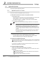
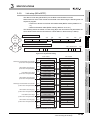
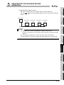
(2) MELSECNET/B data link system
MELSECNET/B data link system is a system which connects the master station and
slave stations (local station and remote I/O station) via a shielded twisted pair cable.
• Up to 31 local and remote I/O stations in total can be connected to one master
station for the second tier.
• Up to 31 local and remote I/O stations in total can be connected to one master
station for the third tier.
Master station
Shielded twisted pair cable
Second tier
Local station
Local station
Local station
No.3
No.2
No.4
No.1
Local station
No.n (n 31)
Local station
Master station
Shielded twisted pair cable
Third tier
Local station
Local station
No.1
No.4
Remote I/O
station
No.3
Local station
No.2
Local station
No.n (n 31)
Local station Station that can mount
local module
Figure 2.2 MELSECNET/B data link system
POINT
A local module cannot be the master station or a remote I/O station since it is a
module dedicated to a local station.
2-2
2.1 Overall System Configuration
SYSTEM CONFIGURATION
1
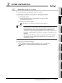
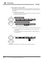
The following shows the combination of the three-tier system other than (1) and
(2) in this section.
(1) When second tier is MELSECNET and third tier is MELSECNET/B
OVERVIEW
Remark
2
R3
Second tier
SYSTEM
CONFIGURATION
M
Station that can mount
local module
L1
L2
m
3
l1
l2
SPECIFICATIONS
Third tier
r3
Figure 2.3 When second tier is MELSECNET and third tier is MELSECNET/B
(2) When second tier is MELSECNET/B and third tier is MELSECNET
4
M
L2
m
r3
Third tier
R3
l1
5
Station that can mount
local module
PREPARATORY
PROCEDURES BEFORE
OPERATION
L1
FUNCTIONS
Second tier
l2
Figure 2.4 When second tier is MELSECNET/B and third tier is MELSECNET
LINK DATA SEND/
RECEIVE PROCESSING
AND PROCESSING TIME
6
PROGRAMMING
7
8
TROUBLESHOOTING
2
2.1 Overall System Configuration
2-3
2
2.2
SYSTEM CONFIGURATION
Applicable Systems
This section describes applicable systems.
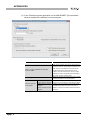
2.2.1
Applicable system for Q series
This section describes the applicable system for Q series.
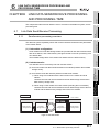
(1) Mountable modules and number of mountable modules
(a) Mountable modules
High Performance model CPU and Universal model QCPU with a serial number
(first five digits) of "13102" or later (excluding the QnUDPVCPU)
QA1S5 B, QA1S6 B, or "QA6 B + A-A1S module conversion adapter"
(b) Number of mountable modules
QCPU User’s Manual (Hardware Design, Maintenance and Inspection)
POINT
• Depending on the combination with other modules or the number of
mounted modules, power supply capacity may be insufficient. Pay
attention to the power supply capacity before mounting modules, and if
the power supply capacity is insufficient, change the combination of the
modules.
• Mount a module within the number of I/O points for the CPU module. If
the number of slots is within the available range, the module can be
mounted on any slot.
(c) When the module is used in a MELSECNET/H remote I/O station
The local module cannot be used in a MELSECNET/H remote I/O station.
Mount the module with a CPU module of the master station.
(2) Support of a multiple CPU system
When the local module is used in the multiple CPU system, refer to the following first:
"PRECAUTIONS FOR USE OF AnS/A SERIES MODULE" in the QCPU User’s
Manual (Multiple CPU System)
For AnS series compatible I/O modules and special function modules, set up the
identical CPU module as the control CPU.
(3) Supported software packages
Using a local module requires GX Developer or GX Works2.
For the version of software package compatible with the CPU module used, refer to
the following:
• With the single CPU system
QCPU User’s Manual (Hardware Design, Maintenance and Inspection)
• With the multiple CPU system
QCPU User’s Manual (Multiple CPU System)
2-4
2.2 Applicable Systems
2.2.1 Applicable system for Q series
SYSTEM CONFIGURATION
1
Applicable system for L series
OVERVIEW
This section describes the applicable system for L series.
(1) Mountable modules and number of mountable modules
2
SYSTEM
CONFIGURATION
(a) Mountable modules
LCPU with a serial number (first five digits) of "16112" or later
LA1S extension base unit
(b) Number of mountable modules
MELSEC-L LA1S Extension Base Unit User’s Manual
4
FUNCTIONS
• Depending on the combination with other modules or the number of
mounted modules, power supply capacity may be insufficient. Pay
attention to the power supply capacity before mounting modules, and if
the power supply capacity is insufficient, change the combination of the
modules.
• Mount a module within the number of I/O points for the CPU module. If
the number of slots is within the available range, the module can be
mounted on any slot.
SPECIFICATIONS
3
POINT
(2) Supported software package
5
PREPARATORY
PROCEDURES BEFORE
OPERATION
For the supported version of software package, refer to the following:
MELSEC-L LA1S Extension Base Module User’s Manual
LINK DATA SEND/
RECEIVE PROCESSING
AND PROCESSING TIME
6
7
PROGRAMMING
2.2.2
8
TROUBLESHOOTING
2
2.2 Applicable Systems
2.2.2 Applicable system for L series
2-5
3
SPECIFICATIONS
CHAPTER3
SPECIFICATIONS
This chapter describes performance specifications and function list of a local module.
For general specifications, refer to the following manual.
User's manual for the CPU module used (Hardware Design, Maintenance and
Inspection)
3.1
Performance Specifications
This section describes the performance specifications of the MELSECNET or
MELSECNET/B data link system and the local module.
(1) Performance specifications of MELSECNET data link system and
A1SJ71AP23Q
Table 3.1 Performance specifications of MELSECNET data link system and A1SJ71AP23Q
Specifications
MELSECNET data link system
Item
MELSECNET mode
Input (X)
MELSECNET II composite
mode
Up to the maximum number of I/O points for the CPU module used in the master station is
applicable.
Maximum applicable
link points per station
MELSECNET II mode
(The total number of link points for slave station is equal to the number of link using points for the
Output (Y)
master station)
Maximum link points
in a system
Link relay (B)
Link register
(W)
Master station
Maximum link points
per station
Local station
Remote I/O
station
Communication speed
1024 points (128 byte)
4096 points (512 byte)
1024 points (2048 byte)
4096 points (8192 byte)
1024 byte
1024 byte (First half of link parameters)
1024 byte (Latter half of link parameters)
512 byte
Number of I/O points: 512
512 byte
-
points
Number of I/O points: 512
points
1.25Mbps
Communication method
Half duplex bit serial method
Synchronization method
Frame synchronization method
Transmission path
Duplex loop
Overall cable distance
Up to 10km (Station-to-station 1km)
Number of connected stations
Up to 65 (Master station: 1, The total number of local stations and remote I/O stations: 64)
Modulation method
CMI method
Transmission format
Conforming to HDLC (Frame format)
Error control system
Retries due to CRC (generating polynomial X16 + X12 + X5 +1) and time out
•Loopback function due to error detection and cable break
RAS function
•Diagnostic function including link line check of host station etc.
Connector
2-core optical connector plug (User prepared*1)
Applicable cable
Optical fiber cable (User prepared*1)
Number of I/O occupied points
32 points (Intelli: 32 points)
Internal current consumption (5VDC)
0.33A
Weight
0.30kg
* 1 Connecting an optical fiber cable with a connector requires professional skills and special tools.
Also, a connector dedicated to an optical fiber cable is required.
For purchase, contact your local Mitsubishi Electric System Service or representative.
3-1
3.1 Performance Specifications
SPECIFICATIONS
1
OVERVIEW
(2) Performance specifications of MELSECNET data link system and
A1SJ71AR23Q
Table 3.2 Performance specifications of MELSECNET data link system and A1SJ71AR23Q
Specifications
MELSECNET data link system
MELSECNET mode
Input (X)
MELSECNET II composite
Output (Y)
(The total number of link points for slave station is equal to the number of link using points for the
master station)
(W)
Master station
Maximum link points
per station
Local station
Remote I/O
station
1024 points (128 byte)
4096 points (512 byte)
1024 points (2048 byte)
4096 points (8192 byte)
1024 byte
1024 byte (First half of link parameters)
1024 byte (Latter half of link parameters)
512 byte
Number of I/O points: 512
512 byte
-
Number of I/O points: 512
points
Communication speed
1.25Mbps
Communication method
Half duplex bit serial method
Synchronization method
Frame synchronization method
3
points
Transmission path
Duplex loop
Overall cable distance
Up to 10km (Station-to-station 500m)
Number of connected stations
Up to 65 (Master station: 1, The total number of local stations and remote I/O stations: 64)
Modulation method
CMI method
Transmission format
Conforming to HDLC (Frame format)
Error control system
Retries due to CRC (generating polynomial X16 + X12 + X5 +1) and time out
RAS function
4
FUNCTIONS
in a system
Link register
5
PREPARATORY
PROCEDURES BEFORE
OPERATION
Maximum link points
Link relay (B)
•Loopback function due to error detection and cable disconnection
•Diagnostic function including link line check of host station etc.
Connector plug for 3C-2V (User prepared):
•BNC-P-3-NiCAu-CF (DDK Ltd.)
Connector
Connector plug for 5C-2V (User prepared):
•BNC-P-5-NiCAu-CF (DDK Ltd.)
6
Cables equivalent to 3C-2V or 5C-2V (User prepared)
Number of I/O occupied points
32 points (Intelli: 32 points)
0.33kg
7
PROGRAMMING
0.80A
Weight
8
TROUBLESHOOTING
Internal current consumption (5VDC)
LINK DATA SEND/
RECEIVE PROCESSING
AND PROCESSING TIME
•BNC-P-5DV SA(41) (HIROSE ELECTRIC CO., LTD.)
Applicable cable
2
mode
Up to the maximum number of I/O points for the CPU module used in the master station is
applicable.
Maximum applicable
link points per station
MELSECNET II mode
SYSTEM
CONFIGURATION
Item
SPECIFICATIONS
3
3.1 Performance Specifications
3-2
3
SPECIFICATIONS
(3) Performance specifications of MELSECNET/B data link system and
A1SJ71AT23BQ
Table 3.3 Performance specifications of MELSECNET/B data link system and A1SJ71AT23BQ
Specifications
MELSECNET/B data link system
Item
MELSECNET mode
Input (X)
MELSECNET II composite
mode
Up to the maximum number of I/O points for the CPU module used in the master station is
applicable.
Maximum applicable
link points per station
MELSECNET II mode
Output (Y)
(The total number of link points for slave station is equal to the number of link using points for the
master station)
Maximum link points
in a system
Link relay (B)
Link register
(W)
Master station
Maximum link points
per station
Local station
Remote I/O
station
Communication speed
1024 points (128 byte)
4096 points (512 byte)
1024 points (2048 byte)
4096 points (8192 byte)
1024 byte
1024 byte (Latter half of link parameters)
512 byte
Number of I/O points: 512
512 byte
-
points
Number of I/O points: 512
points
125kbps/250kbps/500kbps/1Mbps
Communication method
Half duplex bit serial method
Synchronization method
Frame synchronization method
Transmission path
Bus method
Overall cable distance
1024 byte (First half of link parameters)
Changed due to communication speed
(125kbps: 1200m, 250kbps: 600m, 500kbps: 400m, 1Mbps: 200m)
Number of connected stations
Up to 32 (Master station: 1, The total number of local stations and remote I/O stations: 31)
Modulation method
NRZI method
Transmission format
Conforming to HDLC (Frame format)
Error control system
Retries due to CRC (generating polynomial X16 + X12 + X5 + 1) and time out
RAS function
Diagnostic function including link line check of host station etc.
Connector
Terminal block
Applicable cable
Shielded twisted pair cable (User prepared)
Number of I/O occupied points
32 points (Intelli: 32 points)
Internal current consumption (5VDC)
0.66A
Weight
0.22kg
3-3
3.1 Performance Specifications
SPECIFICATIONS
1
Overall cable distance
of MELSECNET
M
L1
L6 MELSECNET R2
R5
2
SYSTEM
CONFIGURATION
Overall cable distance
(1) MELSECNET data link system
The overall cable distance refers to a distance from OUT of the master station
to IN of the master station via a slave station.
OVERVIEW
Remark
3
L3
Figure 3.1 Overall cable distance of MELSECNET
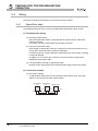
(2) MELSECNET/B data link system
The overall cable distance refers to a distance between stations at both ends.
The overall cable distance of the MELSECNET/B data link system is
determined depending on communication speed.
The communication speed is set by the communication speed setting switch
of each link module.
Table 3.4 Communication speed and overall cable distance
Overall cable distance
1200m
250kbps
600m
500kbps
400m
1Mbps
200m
5
PREPARATORY
PROCEDURES BEFORE
OPERATION
Communication speed
125kbps
Overall cable distance of MELSECNET/B
M
L1
L2
4
FUNCTIONS
Section 5.3 Part Names and Settings
SPECIFICATIONS
R4
L3
6
LINK DATA SEND/
RECEIVE PROCESSING
AND PROCESSING TIME
Figure 3.2 Overall cable distance of MELSECNET/B
PROGRAMMING
7
8
TROUBLESHOOTING
3
3.1 Performance Specifications
3-4
3
3.2
SPECIFICATIONS
Cable Specifications
This section describes the specifications of a cable used in the MELSECNET or
MELSECNET/B data link system.
3.2.1
Optical fiber cable
The following shows the specifications of an optical fiber cable used in the MELSECNET
data link system.
For details of the optical fiber cable specifications, refer to the catalogs of optical fiber
cables.
Connecting an optical fiber cable with a connector requires professional skills and special
tools. Also, a connector dedicated to optical fiber cables is required.
Optical fiber cables with connectors can be purchased in Mitsubishi Electric System
Service or representative.
In addition, they can provide installation service. Contact your local Mitsubishi Electric
System Service or representative.
Table 3.5 Specifications of optical fiber cable
Item
SI (Multicomponent glass)
H-PCF (Plastic clad)
Station-to-station distance
1km
1km
Transmission loss
12dB/km
6dB/km
Core diameter
200
m
200
m
Clad diameter
220
m
250
m
m
-
Primary film
250
Applicable connector
Connectors equivalent to F06/F08 (Conforming to JIS C 5975/5977)
Remark
(1) Types of optical fiber cables are as follows:
A type: Cable for connecting the inside of a control panel
B type: Cable for connecting control panels inside
C type: Cable for connecting control panels outside
D type: Reinforced cable for connecting control panels outside
Since there are cables for specific use including move and heat resistance,
contact Mitsubishi Service or representative.
3-5
3.2 Cable Specifications
3.2.1 Optical fiber cable
3
SPECIFICATIONS
1
The following shows the specifications of a coaxial cable used in the MELSECNET data
link system.
As for a coaxial cable, use "3C-2V" or "5C-2V" (conforming to JIS C 3501) of a highfrequency coaxial cable.
The following shows the specifications of a coaxial cable.
As for a coaxial cable, choose the one which meets the operating ambient
temperature (0 to 55 ) described in the general specification.
3
Table 3.6 Specifications of coaxial cable
3C-2V
Structure
5C-2V
Internal conductor
Insulator
External conductor
External sheath
5.4mm
7.4mm
Allowable bend radius
22mm or more
30mm or more
0.5mm (Annealed copper wire)
0.8mm (Annealed copper wire)
3.1mm (Polyethylene)
4.9mm (Polyethylene)
3.8mm (Single annealed copper wire mesh)
5.6mm (Single annealed copper wire mesh)
conductor
Applicable connector
Connector plug for 3C-2V:
plug
•BNC-P-3-NiCAu-CF (DDK Ltd.)
5
Connector plug for 5C-2V:
•BNC-P-5-NiCAu-CF (DDK Ltd.)
•BNC-P-5DV SA(41) (HIROSE ELECTRIC CO., LTD.)
6
LINK DATA SEND/
RECEIVE PROCESSING
AND PROCESSING TIME
Diameter of external
7
PROGRAMMING
Diameter of insulator
8
TROUBLESHOOTING
conductor
4
FUNCTIONS
Cable diameter
Diameter of internal
SPECIFICATIONS
Item
2
SYSTEM
CONFIGURATION
(1) Specifications of coaxial cable
OVERVIEW
Coaxial cable
PREPARATORY
PROCEDURES BEFORE
OPERATION
3.2.2
3.2 Cable Specifications
3.2.2 Coaxial cable
3-6
3
SPECIFICATIONS
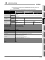
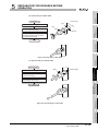
(2) Connection of connector for coaxial cable
The following shows how to connect a BCN connector (connector plug for coaxial
cable) and a cable.
(a) Components of BNC connector and coaxial cable
Components of BCN connector
Nut
Components of coaxial cable
Washer
External conductor
External sheath Insulator
Gasket
Plug shell
Clamp
Internal conductor
Contact
Figure 3.3 Components of BNC connector and coaxial cable
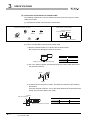
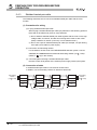
(b) How to connect BNC connector and coaxial cable
1) Remove external sheath of a coaxial cable as shown below.
Be careful not to damage an external conductor.
A
Cable
A
3C-2V
15mm
5C-2V
10mm
Measures for removing external sheath
2) Put a nut, washer, gasket, and clamp through the coaxial cable and unravel
the external conductor.
Clamp
Nut
Washer
Gasket
3) Cut the external conductor, insulator, and internal conductor in the following
dimensions.
As for the external conductor, cut it in the same dimensions as taper part of the
clamp, and smooth it down to the clamp.
Insulator
Internal conductor
B
C
3-7
3.2 Cable Specifications
3.2.2 Coaxial cable
Clamp and external conductor
Cable
B
C
3C-2V
3mm
6mm
5C-2V
5mm
7mm
SPECIFICATIONS
1
OVERVIEW
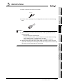
4) Solder a contact to the internal conductor.
Soldered
5) Insert a contact assembly in 4) to a plug shell and screw a nut into the plug
shell.
SYSTEM
CONFIGURATION
2
4
FUNCTIONS
(1) When soldering an internal conductor and a contact, pay attention to the
following points.
• Do not swell up the soldered part.
• Properly solder a contact and an insulator of the cable without making
space between them or soldering them too tight.
• Perform soldering immediately so as not to modify the insulator.
(2) Before removing/mounting the coaxial cable connector, be sure to touch a
grounded metal object to discharge the static electricity from the human body.
Not doing so may cause failure of the module.
5
PREPARATORY
PROCEDURES BEFORE
OPERATION
POINT
SPECIFICATIONS
3
LINK DATA SEND/
RECEIVE PROCESSING
AND PROCESSING TIME
6
PROGRAMMING
7
8
TROUBLESHOOTING
3
3.2 Cable Specifications
3.2.2 Coaxial cable
3-8
3
SPECIFICATIONS
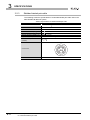
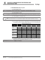
3.2.3
Shielded twisted pair cable
The following shows the specifications of a shielded twisted pair cable used in the
MELSECNET/B data link system.
Table 3.7 Specifications of shielded twisted pair cable
Item
Description
Model name
KNPEV-SB 0.5SQ 1P
Cable
Shielded twisted pair cable
Core
2-core
Conductor resistance (20 )
39.4 /km or less
Insulation resistance (20 )
10M
Dielectric withstand voltage V-min
1000VAC 1 minute
Capacitance (1KHz)
70nF/km or less on average
Characteristic impedance
(100KHz)
Cross section
110
km or more
10
Blue
White
Maker
3-9
3.2 Cable Specifications
3.2.3 Shielded twisted pair cable
TOA ELECTRIC INDUSTRIAL CO., LTD
SPECIFICATIONS
1
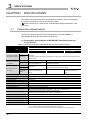
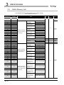
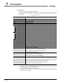
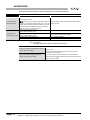
This section describes a function list of a local module.
Table 3.8 Function list
Reference
section
1: n communication Data is communicated between the master station and a local station and between
local stations.
communication)
Note that Q series local stations refresh link data using the sequence program.
1:1 communication
The 1:1 data communication is performed between the master station and a local
(X/Y
station.
communication)
Note that Q series local stations refresh link data using the sequence program.
Section
4.1.1
Section
4.1.2
3
By executing the LRDP/LWTP instruction in the sequence program of the master
Transient
LRDP/LWTP
station, data can be read from or written to local station devices (T, C, D, W).
transmission
instruction
Note that Q series local stations handle the reception of the LRDP/LWTP
Section 4.2
instruction with the sequence program.
Automatic return
When a local station disconnected due to a data link error is recovered, the station
automatically returns to the network and restarts data link.
Disconnects a faulty part such as a disconnected cable or a faulty station from the
Loopback
network to continue data link among normally operating stations. (Not provided for
the MELSECNET/B data link system)
Section
4.3.1
Section
4.3.2
4
Refreshes a special relay (for link) and special register (for link) of a local module
RAS function
to a device of the CPU.
Error detection
The data link status or faulty part can be checked by using the refreshed device.
Section
Note that the network diagnostics of GX Developer is not available for Q series
4.3.3
local stations. Check the data link status or a faulty part in the above-mentioned
way.
Self-diagnostics
Checks the hardware or cable wiring of a local module.
Section 5.5
POINT
(1) Access to another station from peripheral or intelligent function module
Access to another station is not allowed for any peripheral (GX Developer,
GOT, etc.) and intelligent function module (e.g. serial communication module)
connected to a Q series local station.
Also, any peripheral and special function module connected to the master
station cannot access any Q series local station.
Section 4.2 Transient Transmission Function
FUNCTIONS
Cyclic transmission
(B/W
2
SYSTEM
CONFIGURATION
Description
SPECIFICATIONS
Function
OVERVIEW
Function List
5
PREPARATORY
PROCEDURES BEFORE
OPERATION
3.3
6
LINK DATA SEND/
RECEIVE PROCESSING
AND PROCESSING TIME
3
PROGRAMMING
7
TROUBLESHOOTING
8
3.3 Function List
3 - 10
3
SPECIFICATIONS
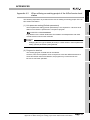
3.4
I/O Signal for Programmable Controller CPU
3.4.1
List of I/O signal
The following shows the list of I/O signal of a local module to the programmable controller
CPU.
The I/O signal is assigned, assuming that start I/O number of a local module is "0000".
Replace it with the I/O signal of a slot where the local module is mounted.
Note that a local module cannot be mounted to the main base unit.
The device X is an input signal from a local module to the programmable controller CPU,
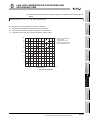
and the device Y is an output signal from the programmable controller to a local module.
Table 3.9 List of I/O signal
Signal direction
Local module
Signal direction
Programmable controller CPU
Device
Signal name
No.
Programmable controller CPU
Device
Signal name
No.
Link status
X0
OFF: Online
Y0
ON: Offline, station-to-station test, or self-loopback test
B/W initial value setting status
X1
OFF: B/W initial value setting completed
Y1
ON: B/W initial value setting in execution
X2
Y2
X3
X4
Y3
Use prohibited
X5
Y4
Y5
X6
Y6
Refresh ready status
X7
OFF: refresh not requested
Y7
ON: Refresh requested
X8
Y8
X9
Y9
XA
YA
XB
XC
Use prohibited
YB
YC
XD
YD
XE
YE
XF
YF
3 - 11
3.4 I/O Signal for Programmable Controller CPU
3.4.1 List of I/O signal
Local module
Use prohibited
3
SPECIFICATIONS
1
Table 3.9 List of I/O signal(Continued)
Device
Signal name
No.
Signal direction
Programmable controller CPU
Programmable controller CPU
Device
Local module
OVERVIEW
Signal direction
Local module
Signal name
No.
CPU operating status
X10
Y10
2
OFF: STOP status, ERROR status
ON: RUN status
Refresh in execution
Y11
OFF: Refresh not executed
SYSTEM
CONFIGURATION
X11
ON: Refresh in execution
X12
Y12
X13
Y13
X14
Y14
X15
Y15
3
Refresh request
Y16
OFF: Refresh not requested
SPECIFICATIONS
Use prohibited
ON: Refresh requested
Y17
X18
Y18
X19
Y19
X1A
Y1A
X1B
Y1B
X1C
Y1C
X1D
Y1D
X1E
Y1E
X1F
Y1F
4
Use prohibited
FUNCTIONS
X17
POINT
Do not turn ON "use prohibited" signals among I/O signals for the programmable
controller CPU.
Doing so may cause malfunction of the programmable controller system.
5
PREPARATORY
PROCEDURES BEFORE
OPERATION
X16
Use prohibited
LINK DATA SEND/
RECEIVE PROCESSING
AND PROCESSING TIME
6
PROGRAMMING
7
TROUBLESHOOTING
8
3.4 I/O Signal for Programmable Controller CPU
3.4.1 List of I/O signal
3 - 12
3
SPECIFICATIONS
3.4.2
Details of I/O signal
The following shows details of I/O signal of a local module.
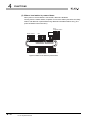
(1) Link status (X0)
The link status is turned ON when the host station is offline, station-to-station test, or
self-loopback test.
The link status is turned OFF when setting the host station online and turning power
supply ON from OFF or resetting the CPU module.
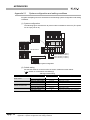
(2) B/W initial value setting status (X1), Refresh ready status (X7), CPU
operating status (Y10), Refresh in execution (Y11), and Refresh request
(Y16)
Operations of link refresh are shown below.
For the programming, refer to the following.
CHAPTER 7 PROGRAMMING
Link scan
Local module
Link data storage area
Sending/receiving data
Sending/receiving data
(Buffer memory address: 100H to 13FFH)
CPU module
Sequence scan
Power-on 0
END
0
END
0
END
0
END
B/W initial value setting status (X1)
Refresh ready status (X7)
CPU operating status (DY10)
Refresh in execution (DY11)
Refresh request (DY16)
Device memory storage area
At power-on, sending/receiving
data to/from other station is started
after setting the B/W initial value.
Program for refresh
Figure 3.4 Operation of link refresh
(a) Turning power supply ON from OFF or resetting the CPU module
1) A local module turns ON the B/W initial value setting status (X1).
2) The B/W device of the CPU module is written to the B/W device of the local
module in a sequence program.
3) When CPU operating status (DY10) and Refresh request (DY16) are turned
ON in a sequence program after writing the initial value to the B/W device of
the local module, a Q series local station starts data communication with other
stations.
3 - 13
3.4 I/O Signal for Programmable Controller CPU
3.4.2 Details of I/O signal
SPECIFICATIONS
1
2) In a sequence program, turn ON Refresh in execution (DY11) and refresh
devices for the local module and the CPU module using the following area.
• Presence or absence of refresh information table (Buffer memory
address: 0H, 1H)
• Refresh information table (Buffer memory address: 2H to 27H)
• Link data storage area (Buffer memory address: 100H to 13FFH)
3) After refresh is completed, turn OFF Refresh in execution (DY11) and Refresh
request (DY16) in the sequence program.
4) When the refresh request (DY16) is turned ON by sequence programs, the
refresh ready status (X7) is turned OFF.
After sequence scans where the refresh ready status (X7) is turned OFF, Q
series local stations restart data sending/receiving from other stations.
POINT
SYSTEM
CONFIGURATION
SPECIFICATIONS
5
6
7
PROGRAMMING
Read/write the buffer memory from/to the sequence scan where Refresh ready
status (X7) is ON.
When the sequence scan is read/written to/from the sequence scan where
Refresh ready status (X7) is OFF, the sequence scan time for the host station may
be prolonged, or the CPU module may stop due to SP.UNIT DOWN.
4
FUNCTIONS
1) A local module turns ON Refresh ready status (X7) when a link scan is
completed and refresh is ready.
During a sequence scan when Refresh ready status (X7) is turned ON, a Q
series local station stops data communication with other stations.
3
PREPARATORY
PROCEDURES BEFORE
OPERATION
(b) Link refresh of link data
2
LINK DATA SEND/
RECEIVE PROCESSING
AND PROCESSING TIME
(1) After turning power supply ON from OFF or resetting the CPU module, be
sure to transfer the initial value of the B/W device to a local module before a Q
series local station communicates data with other stations.
(2) When turning power supply ON from OFF or resetting the CPU module at the
STOP status of the CPU module, data communication with other stations is
not started.
The master station treats a local station as a faulty station (relevant bit in
D9228 to D9231 is turned ON).
When executing a program for refresh (Y10=ON) at the RUN status of the
CPU module, data communication with other stations is started.
OVERVIEW
POINT
8
TROUBLESHOOTING
3
3.4 I/O Signal for Programmable Controller CPU
3.4.2 Details of I/O signal
3 - 14
3
SPECIFICATIONS
3.5
Buffer Memory List
The following shows a buffer memory list of a local module.
Table 3.10 Buffer memory list
Address
Name
Hexadecimal
Decimal
0H to 1H
0 to 1
2H
2
Host station send
Start number (0 to FFF)
3H
3
range of W
Points (in units of words)
4H
4
Other station send
Start number (0 to FFF)
5H
5
range (1) of W
Points (in units of words)
6H
6
Other station send
Start number (0 to FFF)
7H
7
range (2) of W
Points (in units of words)
8H
8
Host station send
Start number (0 to FF0)
9H
9
range of B
Points (in units of words)
AH
10
Other station send
Start number (0 to FF0)
BH
11
CH
12
DH
EH
Refresh information
table (First half of link
Points (in units of words)
Other station send
Start number (0 to FF0)
13
range (2) of B
Points (in units of words)
14
Host station send
Start number (0 to 7F0)
FH
15
range of Y
Points (in units of words)
10H
16
System area (Use prohibited)
parameters)
11H
17
Host station receive Start number (0 to 7F0)
12H
18
range of X
13H
19
System area (Use prohibited)
14H
20
Host station send
Start number (0 to FFF)
15H
21
range of W
Points (in units of words)
16H
22
Other station send
Start number (0 to FFF)
17H
23
range (1) of W
Points (in units of words)
18H
24
Other station send
Start number (0 to FFF)
range (2) of W
Points (in units of words)
Host station send
Start number (0 to FF0)
range of B
Points (in units of words)
Refresh information
Points (in units of words)
19H
25
1AH
26
1BH
27
1CH
28
Other station send
Start number (0 to FF0)
1DH
29
range (1) of B
Points (in units of words)
1EH
30
Other station send
Start number (0 to FF0)
1FH
31
range (2) of B
Points (in units of words)
20H
32
Send range of
Start number (0 to FFF)
table (Latter half of
link parameters)
master station for
second tier (first
33
Points (in units of words)
half) of W
22H
34
Send range of
Start number (0 to FF0)
master station for
23H
24H
25H
35
36
Refresh information
second tier (first
table (Send range of
half) of B
master station for the
Send range of
second tier)
master station for
37
second tier (latter
Points (in units of words)
Start number (0 to FFF)
Points (in units of words)
half) of W
26H
38
Send range of
Start number (0 to FF0)
master station for
27H
39
second tier (latter
half) of B
3 - 15
Readable/ Reference
value
Writable*1
3.5 Buffer Memory List
Points (in units of words)
section
Section
Presence or absence of refresh information table
range (1) of B
21H
Initial
3.6.2
0
R
Section
3.6.3
-
-
0
R
-
-
0
R
Section
3.6.3
-
Section
3.6.3
3
SPECIFICATIONS
Initial
Readable/ Reference
value
Writable*1
section
System area (Use prohibited)
-
-
-
172
LRDP instruction receive request
0
R
173
System area (Use prohibited)
-
-
40 to 171
ACH
ADH
AEH
174
LWTP instruction receive request
0
R
AFH
175
System area (Use prohibited)
-
-
B0H to D7H
176 to 215
216 to 255
LRDP instruction work area
R/W
LWTP instruction work area
256 to 259
Special relay (for link) (M9200 to M9255)
0
R
104H to 10FH
260 to 271
System area (Use prohibited)
-
-
110H to 147H
272 to 327
Special register (for link) (D9200 to D9255)
0
R
148H to 14FH
328 to 335
System area (Use prohibited)
-
-
150H to 1CFH
336 to 463
1D0H to 24FH
464 to 591
area
Input (X0 to X7FF)
Output (Y0 to Y7FF)
250H to 34FH
592 to 847
Link relay (B0 to BFFF)
350H to 3FFH
848 to 1023
System area (Use prohibited)
Link register (W0 to WFFF)
3.6.4
Section
Section
R/W
-
-
3
3.6.6
Section
3.6.7
3.6.8
4
Section
3.6.9
0
R/W
Section
3.6.10
* 1 Indicates whether reading/writing can be performed with a sequence program.
R: Readable, W: Writable
PREPARATORY
PROCEDURES BEFORE
OPERATION
5
LINK DATA SEND/
RECEIVE PROCESSING
AND PROCESSING TIME
6
7
PROGRAMMING
1024 to 5119
3.6.5
Section
0
2
8
TROUBLESHOOTING
400H to 13FFH
Section
3.6.5
100H to 103H
Link data storage
3.6.4
Section
0
B8H to FFH
Section
SYSTEM
CONFIGURATION
28H to ABH
Name
SPECIFICATIONS
Decimal
FUNCTIONS
Address
Hexadecimal
OVERVIEW
1
Table 3.10 Buffer memory list(Continued)
3.5 Buffer Memory List
3 - 16
3
3.6
SPECIFICATIONS
Details of Buffer Memory
This section describes details of a buffer memory of a local module.
3.6.1
Precautions
(1) Reading/writing a buffer memory
Read/write the buffer memory from/to the sequence scan where Refresh ready status
(X7) is ON.
When the sequence scan is read/written to/from the sequence scan where Refresh
ready status (X7) is OFF, the sequence scan time for the host station may be
prolonged, or the CPU module may stop due to SP.UNIT DOWN.
(2) Buffer memory batch monitor/test of GX Developer
Buffer memory batch monitor/test of GX Developer cannot be used.
When executing buffer memory batch monitor/test of GX Developer, the sequence
scan time for the host station may be prolonged, or the CPU module may stop due to
SP.UNIT DOWN.
In addition, when the host station is offline, station-to-station test or self-loopback test,
a communication error occurs to GX Developer.
When monitoring/testing link data storage area of a buffer memory, monitor/test the
device of the refresh target CPU module.
Devices of the CPU module can be checked by the device batch monitor/test of GX
Developer.
3 - 17
3.6 Details of Buffer Memory
3.6.1 Precautions
SPECIFICATIONS
1
Validity/invalidity of each table of refresh information table (buffer memory address: 2H to
27H) is stored.
The refresh information table is created at the time of receiving link parameters from the
master station.
to
b8 b7
to
b0
0: No setting, 1: With setting
Host station send range of W
Other station send range (1) of W
Other station send range (2) of W
Host station send range of B
First half of link parameters
Other station send range (1) of B
Other station send range (2) of B
Host station send range of Y
Host station receive range of X
Host station send range of W
Other station send range (1) of W
Other station send range (2) of W
Latter half of link parameters
Host station send range of B
Other station send range (1) of B
Other station send range (2) of B
(For system)
Special relay (for link), Special register (for link)
Address: 0H
to
(For system)
b2 b1 b0
0: No setting, 1: With setting
Send range of master station for second tier (first half) of B/W
Send range of master station for second tier (latter half) of B/W
4
5
PREPARATORY
PROCEDURES BEFORE
OPERATION
Figure 3.5 Presence or absence of refresh information table
3
LINK DATA SEND/
RECEIVE PROCESSING
AND PROCESSING TIME
6
PROGRAMMING
7
8
TROUBLESHOOTING
b15
Address: 1H
2
SYSTEM
CONFIGURATION
b15
OVERVIEW
Presence or absence of refresh information table
SPECIFICATIONS
3.6.2
FUNCTIONS
3
3.6 Details of Buffer Memory
3.6.2 Presence or absence of refresh information table
3 - 18
3
SPECIFICATIONS
3.6.3
Refresh information table
The refresh information table is stored.
Refresh devices of the local module and CPU module using the refresh information table
in a sequence program.
CHAPTER 7 PROGRAMMING
Local module
103H
13BH
147H
150H
CPU module
Link data storage area
of buffer memory
Device memory
storage area
M9240 to M9255
SM1240 to SM1255
D9243 to D9255
SD1243 to SD1255
X0
Host station receive range
1CFH
X0
Host station receive range
X7FF
X1FFF
Y0
1D0H
Host station send range
24FH
Y0
Host station send range
Y7FF
Y1FFF
250H
Other station send range (1)
(First half of link parameters)
B0
Other station send range (1)
(First half of link parameters)
Host station send range
(First half of link parameters)
Host station send range
(First half of link parameters)
Other station send range (2)
(First half of link parameters)
Other station send range (2)
(First half of link parameters)
Other station send range (1)
(Latter half of link parameters)
Other station send range (1)
(Latter half of link parameters)
Host station send range
(Latter half of link parameters)
Host station send range
(Latter half of link parameters)
Other station send range (2)
(Latter half of link parameters)
Other station send range (2)
(Latter half of link parameters)
34FH
B0
BFFF
B1FFF
400H
Other station send range (1)
(First half of link parameters)
W0
Other station send range (1)
(First half of link parameters)
Host station send range
(First half of link parameters)
Host station send range
(First half of link parameters)
Other station send range (2)
(First half of link parameters)
Other station send range (2)
(First half of link parameters)
Other station send range (1)
(Latter half of link parameters)
Other station send range (1)
(Latter half of link parameters)
Host station send range
(Latter half of link parameters)
Host station send range
(Latter half of link parameters)
Other station send range (2)
(Latter half of link parameters)
Other station send range (2)
(Latter half of link parameters)
13FFH
W0
WFFF
W1FFF
Figure 3.6 Refresh image
3 - 19
3.6 Details of Buffer Memory
3.6.3 Refresh information table
SPECIFICATIONS
1
When a local module is a local station in the second tier (L1 station), each station
send range of B/W is stored as follows:
300
L1
L2
Other station send range (1) Host station send range
Start number: 0000H
Start number: 0100H
Number of points: 0100H
Number of points: 0100H
B/W 0
Link parameter assignment
example (2)
100
L1
200
B/W 0
Link parameter assignment
example (3)
100
M
2
FFF
(Empty)
Other station send range (2)
Start number: 0200H
Number of points: 0180H
L2
380
L3
FFF
3
FFF
4
(Empty)
Other station send range (1)
Start number: 0100H
Number of points: 0280H
200
L2
L3
300
M
Host station send range
Start number: 0000H
Number of points: 0100H
380
SYSTEM
CONFIGURATION
M
200
SPECIFICATIONS
100
280
L3
Other station send range (1)
Start number: 0000H
Number of points: 0280H
380
L1
(Empty)
Host station send range
Start number: 0280H
Number of points: 0100H
FUNCTIONS
B/W 0
Link parameter assignment
example (1)
OVERVIEW
(1) Each station send range of B/W
Readable range
Writable range
5
PREPARATORY
PROCEDURES BEFORE
OPERATION
Figure 3.7 Each station send range of B/W for refresh information table
LINK DATA SEND/
RECEIVE PROCESSING
AND PROCESSING TIME
6
PROGRAMMING
7
8
TROUBLESHOOTING
3
3.6 Details of Buffer Memory
3.6.3 Refresh information table
3 - 20
3
SPECIFICATIONS
(2) Storage example of refresh information table
The following shows the storage example of refresh information table for the case
where link parameters are set as shown below and a local module is a local station in
the second tier (L1 station).
Link parameters of second tier
M
B/W 0
L3
Second
tier
L1
L2
100
200
M
L1
Other station
send range (1)
Host station
send range
300
L2
380
FFF
(Empty)
L3
Other station
send range (2)
Readable range
Writable range
Figure 3.8 Link parameter setting
Table 3.11 Storage example of refresh information table
Address
3 - 21
Name
Stored value
Hexadecimal
Decimal
2H
2
Host station send
Start number (0 to FFF)
0100H
3H
3
range of W
Points (in units of words)
0100H
4H
4
Other station send
Start number (0 to FFF)
0000H
5H
5
range (1) of W
Points (in units of words)
0100H
6H
6
Other station send
Start number (0 to FFF)
0200H
7H
7
range (2) of W
Points (in units of words)
0180H
8H
8
Host station send
Start number (0 to FF0)
0100H
9H
9
range of B
Points (in units of words)
0100H
AH
10
Other station send
Start number (0 to FF0)
0000H
BH
11
range (1) of B
Points (in units of words)
0100H
CH
12
Other station send
Start number (0 to FF0)
0200H
DH
13
range (2) of B
Points (in units of words)
0180H
Refresh information table
(First half of link
parameters)
3.6 Details of Buffer Memory
3.6.3 Refresh information table
SPECIFICATIONS
1
When a device read (LRDP instruction) is requested to a Q series local station from the
master station, execute receive processing to the LRDP instruction in a sequence
program.
CHAPTER 7 PROGRAMMING
The following shows operations of a local module at the time of receiving the LRDP
instruction.
CPU module
END
0
END
0
END
0
END
0
END
SPECIFICATIONS
0
2
3
LRDP
Sequence scan
OVERVIEW
LRDP instruction receive request/receive result/work area
SYSTEM
CONFIGURATION
3.6.4
Read command
Read completion device
(1 scan)
Read data storage device
4
100
FUNCTIONS
Link module
Link scan
5
PREPARATORY
PROCEDURES BEFORE
OPERATION
4 (Processing
requested)
Local module
5 (Processing completed)
LRDP instruction receive request
(ACH)
100
Read data (B4H or later)
CPU module
0
END
0
END
0
END
0
END
0
6
END
LINK DATA SEND/
RECEIVE PROCESSING
AND PROCESSING TIME
Sequence scan
Refresh ready status (X7)
Read data storage device
100
Figure 3.9 Operation of local module at the time of receiving LRDP instruction
PROGRAMMING
7
8
TROUBLESHOOTING
3
3.6 Details of Buffer Memory
3.6.4 LRDP instruction receive request/receive result/work area
3 - 22
3
SPECIFICATIONS
(1) LRDP instruction receive request (Buffer memory address: ACH)
The receive request for the LRDP instruction is stored.
4: Processing requested (System sets it when LRDP instruction is accepted.)
5: Processing completed (User has to set it after the read data is stored.)
Other than the above: No request
(2) LRDP instruction work area (Buffer memory address: B0H to D7H)
When the LRDP instruction receive request (buffer memory address: ACH) is "4", the
requested content of the LRDP instruction is stored into the following area.
1) Read the read data (buffer memory address: B4H to D7H) of a local module to
the devices of the CPU module using the following area in a sequence
program.
2) After reading data, set "5" to the LRDP instruction receive request (buffer
memory address: ACH).
3) Send the data which is stored in the read data (buffer memory address: B4H to
D7H) to the master station.
Table 3.12 LRDP instruction work area
Address
Hexadecimal
Item
Description
(Decimal)
Stores a start device name (device code) of the CPU module.
544EH: T
B0H(176)
Read start device name*1
434EH: C
4420H: D
5720H: W
B1H(177)
Read start device No.*1
B2H(178)
System area (Use prohibited)
B3H(179)
B4H to D7H
(180 to 215)
Read data length
Read data
Stores a start device No. of the CPU module.
Stores the number of data to be read.
1 to 32 (Word)
Stores the data to be read.
* 1 Stored value when start device is D100
Table 3.13 Stored value when start device is D100
Address
Hexadecimal
Item (description)
Stored value
(Decimal)
3 - 23
B0H(176)
Read start device name (D)
4420H
B1H(177)
Read start device No. (100)
0064H
3.6 Details of Buffer Memory
3.6.4 LRDP instruction receive request/receive result/work area
SPECIFICATIONS
1
When a device write (LWTP instruction) is requested to a Q series local station from the
master station, execute receive processing to the LWTP instruction in a sequence
program.
CHAPTER 7 PROGRAMMING
The following shows operations of a local module at the time of receiving the LWTP
instruction.
CPU module
END
0
END
0
END
0
END
0
END
SPECIFICATIONS
0
Write command
(1scan)
Write completion device
4
100
Write data storage device
2
3
LWTP
Sequence scan
OVERVIEW
LWTP instruction receive request/receive result/work area
SYSTEM
CONFIGURATION
3.6.5
FUNCTIONS
Link module
Link scan
4 (Processing
requested)
5
PREPARATORY
PROCEDURES BEFORE
OPERATION
Local module
5 (Processing completed)
LWTP instruction receive request
(AEH)
100
Write data (DCH or later)
CPU module
0
END
0
END
0
END
0
END
0
6
END
LINK DATA SEND/
RECEIVE PROCESSING
AND PROCESSING TIME
Sequence scan
Refresh ready status (X7)
Write data storage device
100
Figure 3.10 Operation of local module at the time of receiving LWTP instruction
PROGRAMMING
7
8
TROUBLESHOOTING
3
3.6 Details of Buffer Memory
3.6.5 LWTP instruction receive request/receive result/work area
3 - 24
3
SPECIFICATIONS
(1) LWTP instruction receive request (Buffer memory address: AEH)
The receive request for the LWTP instruction is stored.
4: Processing requested (System sets it when LWTP instruction is accepted.)
5: Processing completed (User has to set it after the write data is stored.)
Other than the above: No request
(2) LWTP instruction work area (Buffer memory address: D8H to FFH)
When the LWTP instruction receive request (buffer memory address: AEH) is "4", the
requested content of the LWTP instruction is stored into the following area.)
1) Write the write data of a local module to the device of the CPU module (buffer
memory address: DCH to FFH) using the following area in a sequence
program.
2) After writing data, set "5" to the LWTP instruction receive request (buffer
memory address: AEH).
3) The processing completion is notified to the master station.
Table 3.14 LWTP instruction work area
Address
Hexadecimal
Item
Description
(Decimal)
Stores a start device name (device code) of the CPU module.
544EH: T
D8H(216)
Write start device name*1
434EH: C
4420H: D
5720H: W
D9H(217)
Write start device No.*1
DAH(218)
System area (Use prohibited)
DBH(219)
Write data length
DCH to FFH
(220 to 255)
Write data
Stores a start device No. of the CPU module.
Stores the number of write data.
1 to 32 (Word)
Stores the write data.
* 1 Stored value when start device is D100
Table 3.15 Stored value when start device is D100
Address
Hexadecimal
Item (description)
Stored value
(Decimal)
3 - 25
D8H(216)
Write start device name (D)
4420H
D9H(217)
Write start device No.(100)
0064H
3.6 Details of Buffer Memory
3.6.5 LWTP instruction receive request/receive result/work area
SPECIFICATIONS
1
to
Address: 100H
101H
102H
103H
b8 b7
M9200
to
(Empty)
b0
3
SPECIFICATIONS
M9208
M9224
M9240
Figure 3.11 Special relay (for link) (M9200 to M9255)
100H
101H
102H
103H
CPU module
Special relay (for link) (M)
Special relay (SM)
M9240 to M9255
SM1240 to SM1255
4
FUNCTIONS
Local module
Figure 3.12 Refresh of special relay (for link) (M)
5
Special register (for link) (D9200 to D9255)
Data of a special register (for link) (D9200 to D9255) is stored.
Refresh devices of the CPU module and the data in this area in a sequence program.
The following shows refresh of special register (for link) (D).
For details of a special register (for link), refer to the following.
Appendix 2 List of Special Registers (for Link)
Local module
Special register (for link) (D)
110H
CPU module
Special register (SD)
13BH
D9243
SD1243
147H
D9255
SD1255
6
7
PROGRAMMING
3.6.7
PREPARATORY
PROCEDURES BEFORE
OPERATION
b15
2
SYSTEM
CONFIGURATION
Data of a special relay (for link) (M9200 to M9255) is stored.
Refresh devices of the CPU module and the data in this area in a sequence program.
The following shows refresh of special relay (for link) (M).
For details of a special relay (for link), refer to the following.
Appendix 1 List of Special Relays (for Link)
OVERVIEW
Special relay (for link) (M9200 to M9255)
LINK DATA SEND/
RECEIVE PROCESSING
AND PROCESSING TIME
3.6.6
Figure 3.13 Refresh of special register (for link) (D)
8
TROUBLESHOOTING
3
3.6 Details of Buffer Memory
3.6.6 Special relay (for link) (M9200 to M9255)
3 - 26
3
SPECIFICATIONS
3.6.8
Input (X0 to X7FF) and output (Y0 to Y7FF)
Data of input (X0 to X7FF) and output (Y0 to Y7FF) of X/Y communication is stored.
Refresh devices of the CPU module and the data in this area using the following area in a
sequence program.
• Presence or absence of refresh information table (Buffer memory address: 0H,
1 H)
• Refresh information table (Buffer memory address: 2H to 27H)
The following shows the refresh of input (X) and output (Y) when link parameters are set
as follows:
Master
station
X
Y
0 Actual I/O
Q series
local station
X
Y
Actual I/O 0
400
400
47F
480
47F
480
4FF
4FF
Figure 3.14 Link parameter setting
Local module
Input (X)
CPU module
Input (X)
150H
Host station
receive range
190H
X400 to X40F
X400 to X40F
197H
X470 to X47F
X470 to X47F
Output (Y)
Output (Y)
218H
Y480 to Y48F
Y480 to Y48F
21FH
Y4F0 to Y4FF
Y4F0 to Y4FF
1CFH
1D0H
Host station
send range
24FH
Figure 3.15 Refresh of input (X) and output (Y)
3 - 27
3.6 Details of Buffer Memory
3.6.8 Input (X0 to X7FF) and output (Y0 to Y7FF)
3
SPECIFICATIONS
1
Link parameters of second tier
M
100
B/W 0
Second
tier
L1
M
200
300
L2/m
L1
400
(Empty)
500
M
First half of link parameters
600
700
L2/m
L1
FFF
Latter half of link parameters
Link parameters of master station for third tier (L2/m)
l1
200
600
280 2C0 300
680 6C0 700
L2/m l1
L2/m l1 l2
First half of link parameters
FFF
4
l2
Latter half of link parameters
Host station send range
(First half of link parameters)
Other station send range (2)
(First half of link parameters)
Send range of master station for second tier
(Latter half of link parameters)
Other station send range (1)
(Latter half of link parameters)
Host station send range
(Latter half of link parameters)
Other station send range (2)
(Latter half of link parameters)
25FH
BF0 to BFF
BF0 to BFF
270H
B200 to B20F
B200 to B20F
277H
278H
B270 to B27F
B280 to B28F
B270 to B27F
B280 to B28F
27BH
27CH
B2B0 to B2BF
B2C0 to B2CF
B2B0 to B2BF
B2C0 to B2CF
27FH
B2F0 to B2FF
B2F0 to B2FF
290H
B400 to B40F
B400 to B40F
29FH
B4F0 to B4FF
B4F0 to B4FF
2B0H
B600 to B60F
B600 to B60F
2B7H
2B8H
B670 to B67F
B680 to B68F
B670 to B67F
B680 to B68F
2BBH
2BCH
B6B0 to B6BF
B6C0 to B6CF
B6B0 to B6BF
B6C0 to B6CF
2BFH
B6F0 to B6FF
B6F0 to B6FF
5
PREPARATORY
PROCEDURES BEFORE
OPERATION
Other station send range (1)
(First half of link parameters)
250H
Link relay (B)
B0 to BF
6
LINK DATA SEND/
RECEIVE PROCESSING
AND PROCESSING TIME
Send range of master station for second tier
(First half of link parameters)
CPU module
Link relay (B)
B0 to BF
7
PROGRAMMING
Local module
FUNCTIONS
Figure 3.16 Link parameter setting
8
TROUBLESHOOTING
l2
B/W 0
3
(Empty)
L2/m
Third
tier
2
SYSTEM
CONFIGURATION
The data of a link relay (B0 to BFFF) for the B/W communication is stored.
Refresh devices of the CPU module and the data in this area using the following area in a
sequence program.
• Presence or absence of refresh information table (Buffer memory address: 0H,
1H)
• Refresh information table (Buffer memory address: 2H to 27H)
The following shows the refresh of a link relay (B) for the case where link parameters are
set as shown below and a local module is a local station in the third tier (l1 station).
OVERVIEW
Link relay (B0 to BFFF)
SPECIFICATIONS
3.6.9
34FH
Figure 3.17 Refresh of link relay (B)
3.6 Details of Buffer Memory
3.6.9 Link relay (B0 to BFFF)
3 - 28
3
SPECIFICATIONS
3.6.10
Link register (W0 to WFFF)
The data of a link register (W0 to WFFF) for the B/W communication is stored.
Refresh devices of the CPU module and the data in this area using the following area in a
sequence program.
• Presence or absence of refresh information table (Buffer memory address: 0H,
1 H)
• Refresh information table (Buffer memory address: 2H to 27H)
The following shows the refresh of a link register (W) for the case where link parameters
are set as shown below and a local module is a local station in the third tier (l1 station).
Link parameters of second tier
M
B/W 0
Second
tier
L1
100
M
200
300
L2/ m
L1
400
(Empty)
500
M
First half of link parameters
600
700
L2/m
L1
FFF
(Empty)
Latter half of link parameters
L2/m
Link parameters of master station for third tier (L2/m)
l2
Third tier
l1
B/W 0
200 280 2C0 300
L2/m l1
l2
First half of link parameters
600
680 6C0 700
L2/m l1 l2
Latter half of link parameters
Figure 3.18 Link parameter setting
Local module
Send range of master station for second tier
(First half of link parameters)
Other station send range (1)
(First half of link parameters)
Host station send range
(First half of link parameters)
Other station send range (2)
(First half of link parameters)
Send range of master station for second tier
(Latter half of link parameters)
Other station send range (1)
(Latter half of link parameters)
Host station send range
(Latter half of link parameters)
Other station send range (2)
(Latter half of link parameters)
400H
4FFH
WFF
WFF
600H
W200
W200
67FH
680H
W27F
W280
W27F
W280
6BFH
6C0H
W2BF
W2C0
W2BF
W2C0
6FFH
W2FF
W2FF
800H
W400
W400
8FFH
W4FF
W4FF
A00H
W600
W600
A7FH
A80H
W67F
W680
W67F
W680
ABFH
AC0H
W6BF
W6C0
W6BF
W6C0
AFFH
W6FF
W6FF
Figure 3.19 Refresh of link register (W)
3 - 29
CPU module
Link register (W)
W0
13FFH
3.6 Details of Buffer Memory
3.6.10 Link register (W0 to WFFF)
FFF
Link register (W)
W0
FUNCTIONS
1
FUNCTIONS
OVERVIEW
CHAPTER4
This chapter describes the functions of the local module.
2
Cyclic Transmission Function
4.1.1
SYSTEM
CONFIGURATION
This function allows cyclic data communication between master and local stations.
1 : n communication (B/W communication)
Data are written to the host station send range in the link relay (B) and link register (W),
and they are sent to other stations.
The link relay (B) handles ON/OFF information, and the link register (W) sends and
receives 16-bit data.
4
Q series local station
Master station
Local module
3
CPU module
Link data
storage area
Link data
storage area
Data memory
storage area
B
B
B
B
W
W
W
W
FUNCTIONS
Buffer memory
Data memory
storage area
PREPARATORY
PROCEDURES BEFORE
OPERATION
5
Local station
Link data
storage area
B
B
W
W
Link refresh
6
LINK DATA SEND/
RECEIVE PROCESSING
AND PROCESSING TIME
Data memory
storage area
Data flow (Send/receive processing)
Link scan
Figure 4.1 B/W communication data flow
PROGRAMMING
7
8
TROUBLESHOOTING
4.1
SPECIFICATIONS
4
4.1 Cyclic Transmission Function
4.1.1 1 : n communication (B/W communication)
4-1
4
FUNCTIONS
(1) Each station send range in B/W
Each station send range in B/W is set up with link parameters of the master station.
The following explains a link parameter setting example and send/receive ranges for
local modules.
(a) Link parameter setting example
Link parameters must be set to the master station for the second tier (M) and the
master station for the third tier (L2/m).
Link parameters for second tier
M
100
B/W 0
L3
Second
tier
L1
M
200
L1
300
L2/m
380
L3
FFF
(Empty)
First half of link parameters
L2/m
Link parameters of master station for third tier (L2/m)
l2
Third
tier
200
B/W 0
l1
280 2C0 300
L2/m
l1
FFF
l2
First half of link parameters
Figure 4.2 Link parameter setting example
(b) Send/receive ranges when the local module is on the second-tier local station (L1)
1) L1 station writes data into the range of B/W100 to 1FF, and sends them to
other stations.
2) It can receive data written by other stations within the ranges of B/W0 to FF
and B/W200 to 37F.
M
B/W 0
L3
Second
tier
L1
100
M
200
L1
280 2C0 300
L2/m
l1 l2
380
L3
FFF
(Empty)
Readable range
L2/m
l2
Third
tier
Writable range
l1
Figure 4.3 Send/receive ranges when the local module is on the second-tier local station (L1)
4-2
4.1 Cyclic Transmission Function
4.1.1 1 : n communication (B/W communication)
4
FUNCTIONS
1
1) l1 station writes data into the range of B/W280 to 2BF, and sends them to other
stations.
M
100
B/W 0
L1
200
M
L1
280 2C0 300
L2/m
l1 l2
380
L3
FFF
(Empty)
3
Readable range
L2/m
SPECIFICATIONS
Third
tier
l2
Writable range
l1
Figure 4.4 Send/receive ranges when the local module is on the third-tier local station (l1)
4
(2) Link refresh of link data
FUNCTIONS
Q series local stations refresh link data using the sequence program. Note that
refresh is not executed when the CPU module is in STOP status.
CHAPTER 7 PROGRAMMING
5
Q series local station
CPU module
PREPARATORY
PROCEDURES BEFORE
OPERATION
Local module
Buffer memory
Link data
storage area
Data memory
storage area
"A part" of the program for refresh
Receive
processing
400H
DMOV
W0 to WFF
W0 to WFF
BMOV
4FFH
500H
Send
processing
DMOV
BMOV W0Z0
U0\
G2
Z0
U0\
Z1
G1024Z0
Data flow
(Send/receive processing)
Link scan
Link refresh
7
Figure 4.5 Link refresh of link data (Q series local station)
PROGRAMMING
5FFH
W100 to W1FF
6
U0\
W0Z0 Z1
G1024Z0
8
TROUBLESHOOTING
W100 to W1FF
U0\
Z0
G4
LINK DATA SEND/
RECEIVE PROCESSING
AND PROCESSING TIME
L3
Second
tier
2
SYSTEM
CONFIGURATION
2) It can receive data written by other stations within the ranges of B/W0 to FF,
B/W200 to 27F, and B/W2C0 to 2FF.
OVERVIEW
(c) Send/receive ranges when the local module is on the third-tier local station (l1)
4.1 Cyclic Transmission Function
4.1.1 1 : n communication (B/W communication)
4-3
4
FUNCTIONS
(3) B/W communication example
The following illustrates an example where link relay (B) data are transferred between
the master station and a Q series local station (L1).
Master station
Program for data link
CPU module
B0
M
Send
request
Link
module
M
CPU module
B0
M
25FH
260H
L1
B1FF
Local module
buffer memory
250H
M
BFF
B100
B0
Q series local station
L1
Program for data link
BFF
B100
L1
26FH
B100
Program for refresh
B0
L1
B1FF
Send
request
B100
END processing
END processing
Cyclic transmission
Link refresh
Figure 4.6 B/W communication example
4-4
4.1 Cyclic Transmission Function
4.1.1 1 : n communication (B/W communication)
FUNCTIONS
1
4.1.2
1 : 1 communication (X/Y communication)
Using a part of the I/O points assigned to a master station and a local station, one-to-one
data communication is performed between the master and local stations.
The sending and receiving sides are regarded as output (Y) and input (X) respectively.
CPU module
Local module
Buffer memory
Link data
storage area
Link data
storage area
Data memory
storage area
X
X
Y
Y
Y
Y
X
X
3
SPECIFICATIONS
Data memory
storage area
2
SYSTEM
CONFIGURATION
Q series local station
Master station
OVERVIEW
4
Data flow (Send/receive processing)
Link scan
Link refresh
Figure 4.7 X/Y communication data flow
4
(1) I/O ranges in X/Y
FUNCTIONS
The I/O ranges of X/Y are set up with link parameters of the master station.
(2) Link refresh of link data
Q series local stations refresh link data using the sequence program. Note that
refresh is not executed when the CPU module is in STOP status.
CHAPTER 7 PROGRAMMING
PREPARATORY
PROCEDURES BEFORE
OPERATION
5
(3) X/Y communication example
The following illustrates an example where input (X) and output (Y) data are
transferred between the master station and a Q series local station.
Link
module
X
Y
LINK DATA SEND/
RECEIVE PROCESSING
AND PROCESSING TIME
Program for data link
CPU module
X
Y
0
Actual I/O
6
Q series local station
Local module
buffer memory CPU module
X
Y
0
Actual I/O
Program for refresh
Program for data link
400
190H
400
47F
480
197H
218H
47F
480
4FF
21FH
4FF
X480
END processing
7
X400
PROGRAMMING
Output
instruction
Y400
Output
instruction
Y480
END processing
8
Cyclic transmission
Link refresh
Figure 4.8 X/Y communication example
4.1 Cyclic Transmission Function
4.1.2 1 : 1 communication (X/Y communication)
4-5
TROUBLESHOOTING
Master station
4
FUNCTIONS
4.2
Transient Transmission Function
When a transient request is made, this function allows data communication between a
master station and a local station.
(1) Communication from a master station to a local station
(a) Communication from a master station to a local station
By executing the LRDP/LWTP instruction in the sequence program of the master
station, data can be read from or written to local station devices (T, C, D, W).
(b) LRDP/LWTP instruction receive processing
Q series local stations handle the reception of the LRDP/LWTP instruction with
the sequence program.
If the LRDP/LWTP instruction is received when the CPU module is in STOP
status, the local module will send an error response to the master station (4:
LRDP/LWTP inexecutable on the station).
CHAPTER 7 PROGRAMMING
Q series local station
Master station
Command
Buffer memory
LWTP
Data memory
storage area
D20 to D29
CPU module
Local module
Link data
storage area
Device
write
DCH
Data memory
storage area
"A part" of the program for receiving LWTP instruction
= K4
Write data
D200 to D209
U0\
G174
DMOV
MOV
= H4420 Z0
Figure 4.9 LWTP instruction receive processing (Q series local station)
4-6
4.2 Transient Transmission Function
BMOV
U0\
Z0
G216
U0\
Z2
G219
U0\
D0Z1 Z2
G220
FUNCTIONS
(2) Access from a peripheral or intelligent function module to another
station
Access to another station is not allowed for any peripheral (GX Developer, GOT, etc.)
and intelligent function module (e.g. serial communication module) connected to a Q
series local station.
Also, any peripheral and special function module connected to the master station
cannot access any Q series local station.
Unable to access a
Q series local station.
2
3
Master station
SPECIFICATIONS
Peripheral
OVERVIEW
1
SYSTEM
CONFIGURATION
4
4
MELSECNET (II)
Local station
Q series local station
FUNCTIONS
Peripheral
5
PREPARATORY
PROCEDURES BEFORE
OPERATION
Unable to access another station.
GX Developer
Figure 4.10 Access from a peripheral or intelligent function module to another station
Peripherals and special function modules connected to a CPU module can access
another station via MELSECNET (II).
The table below shows which station is accessible from a station with a peripheral.
For executable functions, refer to the following manual.
Manual for the relevant peripheral or special function module.
Table 4.1 Station accessible from a station with a peripheral
Local station
Local station
(A/QnA series)
(Q series)
Remote I/O station
*1
(
for host)
Local station (Q series)
PROGRAMMING
Master station
Master station
8
Remote I/O station
: Accessible,
: Not accessible
* 1 Not accessible when GX Developer is used.
4.2 Transient Transmission Function
4-7
TROUBLESHOOTING
Local station (A/QnA series)
7
Accessible station (Access destination)
Station with peripheral
(Access source)
LINK DATA SEND/
RECEIVE PROCESSING
AND PROCESSING TIME
6
Remark
4
4.3
FUNCTIONS
RAS Functions
This chapter explains the RAS functions.
4.3.1
Automatic return function
When a local station disconnected due to a data link error is recovered, this function allows
the station to automatically return to the network and to restart data link.
The automatic return function is set by the mode setting switch of each link module.
Section 5.3 Part Names and Settings
Conditions for reconnecting a disconnected station vary depending on whether the
automatic return function is supported or not, as shown below.
(1) When data link is interrupted due to an error in a master station
Table 4.2 Conditions for reconnecting a disconnected station depending on whether
the automatic return function is supported or not
Automatic return function
Master station
Local station
Supported
Supported
Automatically reconnected after the faulty part of the master station is corrected.
Not supported
Supported
Not supported
Conditions for reconnecting a disconnected station (local station)
Take actions to correct the faulty part of the master station.
Reset the master station, and then the disconnected station.
Automatically reconnected after the faulty part of the master station is corrected.
Not supported
Take actions to correct the faulty part of the master station.
Reset the disconnected station, and then the master station.
(2) When a station is disconnected due to an error occurred in the station
Table 4.3 Conditions for reconnecting a disconnected station depending on whether
the automatic return function is supported or not
Automatic return function
Master station
Local station
Supported
Supported
Not supported
Supported
Not supported
4-8
Not supported
4.3 RAS Functions
4.3.1 Automatic return function
Conditions for reconnecting a disconnected station (local station)
Automatically returns after the faulty part of the disconnected station is corrected.
Take actions to correct the faulty part of the disconnected station.
Reset the disconnected station.
Take actions to correct the faulty part of the disconnected station.
Reset the disconnected station and the local station without automatic return
function, and then the master station.
FUNCTIONS
1
(1) When an error occurs on the forward loop
When a cable disconnection or a cable connector failure occurs on the forward loop,
data link using the forward loop is not executable.
In such a case, the system automatically switches the line from the forward loop to the
reverse loop to continue data link.
Master station
3
SPECIFICATIONS
No.2
2
SYSTEM
CONFIGURATION
This function disconnects a faulty part such as a disconnected cable or a faulty station
from the network, allowing data link to continue among normally operating stations. (Not
provided for the MELSECNET/B data link system)
Normally, data link is performed using the forward loop.
OVERVIEW
Loopback function
No.1
4
Forward loop
FUNCTIONS
Reverse loop
Disconnected
(2) When errors occur on the forward and reverse loops
When cable disconnections or cable connector failures occur on the forward and
reverse loops, data link using these loops is not executable.
Viewing from the master station, loopback occurs at the station just before the fault,
and data link is performed among data-link-executable stations only. (All stations
located between the faulty stations are disconnected.)
No.2,
loopback station
Master station
6
7
No.1
Reverse loop
PREPARATORY
PROCEDURES BEFORE
OPERATION
5
No.4
No.3
Figure 4.11 When an error occurs on the forward loop
LINK DATA SEND/
RECEIVE PROCESSING
AND PROCESSING TIME
No.5
Forward loop
PROGRAMMING
4.3.2
Disconnected
8
Disconnected
TROUBLESHOOTING
4
No.5,
No.3
No.4
loopback station
Figure 4.12 When errors occur on the forward and reverse loops
4.3 RAS Functions
4.3.2 Loopback function
4-9
4
FUNCTIONS
(3) When a local station is powered down
When power of a local station is turned OFF, data link is disabled.
Viewing from the master station, loopback occurs at the station just before the faulty
station, and data link is performed among data-link-executable stations only. (The
power-off station is disconnected.)
No.2,
loopback station
Master station
No.1
Reverse loop
No.5
Forward loop
No.4,
loopback station
No.3 (Power OFF)
Figure 4.13 When a local station is powered down
4 - 10
4.3 RAS Functions
4.3.2 Loopback function
FUNCTIONS
1
2
SYSTEM
CONFIGURATION
Data of the special relay (for link) and special register (for link) of a local module are
refreshed into CPU module devices.
With the refreshed devices, the data link status or a faulty part can be checked.
For details of the special relay (for link) and special register (for link), refer to the following.
Appendix 1 List of Special Relays (for Link)
Appendix 2 List of Special Registers (for Link)
Note that the network diagnostics of GX Developer is not available for Q series local
stations. Check the data link status or a faulty part in the above-mentioned way.
OVERVIEW
Error detection function
SPECIFICATIONS
3
FUNCTIONS
4
PREPARATORY
PROCEDURES BEFORE
OPERATION
5
LINK DATA SEND/
RECEIVE PROCESSING
AND PROCESSING TIME
6
7
PROGRAMMING
4.3.3
8
TROUBLESHOOTING
4
4.3 RAS Functions
4.3.3 Error detection function
4 - 11
5
PREPARATORY PROCEDURES BEFORE
OPERATION
CHAPTER5
PREPARATORY PROCEDURES BEFORE
OPERATION
This chapter describes the procedures up to connect a local module to the network and
wiring procedures.
5.1
Implementation and Installation
This section describes handling precautions, from unpacking to installation of the local
module.
For details of the implementation and installation of the local module, refer to the following:
• For Q series
QCPU User's Manual (Hardware Design, Maintenance and Inspection)
• For L series
MELSEC-L LA1S Extension Base Unit User's Manual
5.1.1
Handling precautions
The following describes precautions for handling the single local module.
(1) Do not drop or give strong impact on the module, since its case is made
of resin.
(2) Do not remove a printed-circuit board of the module from a case.
Doing so may cause failure.
(3) Be careful to prevent foreign matter such as wire chips from entering the
module top at the time of wiring.
(4) Tighten a module mounting screw or a terminal screw within the
following range.
Table 5.1 Screw tightening torque
5-1
Screw
Tightening torque range
Terminal screw for cable terminal block (M3.5 screw)
59 to 88N cm
Mounting screw for cable terminal block (M3.5 screw)
59 to 88N cm
Module mounting screw (M4 screw)
78 to 118N cm
5.1 Implementation and Installation
5.1.1 Handling precautions
OVERVIEW
Preparatory Procedures before Operation
This section describes the outline of preparatory procedures before operation.
Start
2
Check prior to power-on
SYSTEM
CONFIGURATION
Set the RUN/STOP switch of the CPU module to
STOP. Check to see if the external power supply
voltage for the power supply module is within the
stipulated range.
Power-on
Turn ON the external power supply. Check to see if
RUN LED of a local module is turned ON.
3
SPECIFICATIONS
Local module single check
Check the hardware of a local module by the selfloopback test.
Section 5.5.1 Self-loopback test
Connection of cable
4
Connect link modules via a cable.
Section 5.4 Wiring
FUNCTIONS
Line check between two stations
Check the line between the two adjacent stations by
the station-to-station test.
Section 5.5.2 Station-to-station test
5
Link parameter setting for the master station
PREPARATORY
PROCEDURES BEFORE
OPERATION
Set link parameters for the master station.
Type MELSECNET, MELSECNET/B Data
Link System Reference Manual
Programming for refresh
Create a program for refresh. Set the RUN/STOP
switch of the CPU module to RUN, and check the
program.
CHAPTER 7 PROGRAMMING
LINK DATA SEND/
RECEIVE PROCESSING
AND PROCESSING TIME
6
Line check (not provided for MELSECNET/B)
Check the forward loop or reverse loop side line of
the MELSECNET.
Section 5.5.3 Forward loop test/reverse loop
7
Programming and debug
Create a program for data link and check the
program.
Type MELSECNET, MELSECNET/B Data
Link System Reference Manual
PROGRAMMING
5.2
1
END
Figure 5.1 Preparatory procedures before operation
8
POINT
The link parameter setting (refresh parameter) is not required for a Q series local
station since refresh is performed in a sequence program.
5.2 Preparatory Procedures before Operation
5-2
TROUBLESHOOTING
5
PREPARATORY PROCEDURES BEFORE
OPERATION
5
5.3
PREPARATORY PROCEDURES BEFORE
OPERATION
Part Names and Settings
This chapter describes the part names and settings of the local module.
1)
1)
1)
2)
2)
2)
3)
3)
3)
4)
7)
5)
6)
Figure 5.2 Outside drawing of local module
Table 5.2 Part names and settings
No.
Name
LED
Description
Name
Status
RUN
SD
RD
Description
Data link normal
Data sending
ON
Data receiving
F.LOOP
Forward loop side receives data (OFF: Reverse loop side receives data)
CPU
Communication with CPU module in execution
125k
250k
500k
1)
ON
1M
CRC
Code check error of receive data
OVER
The processing of receive data has been delayed.
•"1" has been received consecutively more than stipulated times.
AB.IF
•Receive data length is shorter than stipulated length.
TIME
ON (OFF
Data link monitoring time is over.
DATA
if normal)
The data of error code has been received.
UNDER
UND.
5-3
Setting status of communication speed (A1SJ71AT23BQ)
Internal processing of send data is not executed constantly.
F.LOOP
Receive error at forward loop side
R.LOOP
Receive error at reverse loop side
5.3 Part Names and Settings
5
PREPARATORY PROCEDURES BEFORE
OPERATION
1
Table 5.2 Part names and settings(Continued)
No.
Name
Description
Sets station No. of the local module.(Factory default setting: 1) (Refer to
Ones
place
2)
(1) in this section)
•A1SJ71AP23Q/A1SJ71AR23Q
2
1 to 64: Station No.
(If other than above is set, the local module goes into offline status (X0=ON).)
(A1SJ71AT23BQ)
Tens
place
SYSTEM
CONFIGURATION
•A1SJ71AT23BQ
1 to 31: Station No.
(If other than above is set, the local module goes into offline status (X0=ON).)
Ones
place
3
Sets operation mode.(Factory default setting: 0)
No.
0
Mode setting switch
(A1SJ71AP23Q/
A1SJ71AR23Q)
3)
Description
Data link (with automatic return function)
1
Online
Data link (without automatic return function)
2
Offline
Disconnects host station.
3
-
Unusable (If set, the local module goes into offline status
4
-
(X0=ON.))
5
(A1SJ71AT23BQ)
Item
Online
6
7
8 to F
4
Station-to-station test
(Executing station)
Station-to-station test
Checks a line between two adjacent stations.
(Other station)
Self-loopback test
-
Checks the hardware including transmission circuit in a
single local module.
Unusable (If set, the local module goes into offline status
(X0=ON).)
4)
Communication speed setting
switch (A1SJ71AT23BQ)
Communication speed
0
125kbps
1
250kbps
2
500kbps
3
4 to F
1Mbps
6
Unusable (If set, the local module goes into offline status (X0=ON).)
IN
Reverse loop send
IN
Forward loop receive
7
OUT Forward loop send
PROGRAMMING
OUT Reverse loop receive
8
TROUBLESHOOTING
Connector (A1SJ71AP23Q)
LINK DATA SEND/
RECEIVE PROCESSING
AND PROCESSING TIME
Connects an optical fiber cable.
5)
5
PREPARATORY
PROCEDURES BEFORE
OPERATION
Sets communication speed.
No.
SPECIFICATIONS
Tens
place
FUNCTIONS
(A1SJ71AP23Q/
A1SJ71AR23Q)
OVERVIEW
Station No. setting switch
5.3 Part Names and Settings
5-4
5
PREPARATORY PROCEDURES BEFORE
OPERATION
Table 5.2 Part names and settings(Continued)
No.
Name
Description
Connects a coaxial cable.
6)
Connector (A1SJ71AR23Q)
Reverse loop receive OUT R-RD
IN R-SD
Reverse loop send
Forward loop send
IN F-RD
Forward loop receive
OUT F-SD
Connects a shielded twisted pair cable.
7)
Terminal block
(A1SJ71AT23BQ)
(1) Station No. setting
(a) MELSECNET data link system
Set "00" to the station No. of the master station, and set station No.
(01 02
station.
n(n
64) to slave stations starting from the one next to the master
Master station
for second tier
Station
No.00
IN
Slave station Master station
No.1
for third tier
OUT
Station
Station
Forward
No.01
No.00
loop
direction IN
OUT
OUT IN
Slave station
No.2
Slave station
No.3
Slave station
No.64
Station
No.02
Station
No.03
Station
No.64
IN
OUT
IN
OUT
IN
OUT
Tertiary station Tertiary station Tertiary station
No.1
No.2
No.64
Station
No.01
Forward
loop
direction IN
OUT
Station
No.02
IN
OUT
Station
No.64
IN
OUT
Figure 5.3 Station No. setting of MELSECNET data link system
POINT
(1) Set station No. from the smallest number in order.
(2) Do not skip any station No., since it has to be set in number order.
(3) Set station No. so as not to overlap with other station No. in the same tier.
5-5
5.3 Part Names and Settings
1
(01 02
station.
n(n
31) to slave stations starting from the one next to the master
OVERVIEW
(b) MELSECNET/B data link system
Set "00" to the station No. of the master station, and set station No.
2
Slave station
No.1
Slave station
No.3
Slave station
No.2
Slave station
No.31
Station
No.01
Station
No.03
Station
No.02
Station
No.31
3
Figure 5.4 Station No. setting of MELSECNET/B data link system
POINT
4
FUNCTIONS
(1) The station No. can be set regardless of station number order.
(There is no restriction on connection order of stations including the master
station.)
(2) Do not skip any station No., since it has to be set in number order.
(3) Set station No. so as not to overlap with other station No. in the same tier.
SPECIFICATIONS
Station
No.00
SYSTEM
CONFIGURATION
Master station
PREPARATORY
PROCEDURES BEFORE
OPERATION
5
LINK DATA SEND/
RECEIVE PROCESSING
AND PROCESSING TIME
6
PROGRAMMING
7
8
TROUBLESHOOTING
5
PREPARATORY PROCEDURES BEFORE
OPERATION
5.3 Part Names and Settings
5-6
5
5.4
PREPARATORY PROCEDURES BEFORE
OPERATION
Wiring
This section describes precautions for connecting and wiring cables.
5.4.1
Optical fiber cable
The following describes how to connect an optical fiber cable with the local module.
(1) Precautions for wiring
(a) Securing of wiring space
When an optical fiber cable is connected with the local module, a cable bend
radius is restricted.
For details, check the specifications of the cable to be used.
(b) Laying an optical fiber cable
When laying an optical fiber cable, do not directly touch an optical fiber core of a
plug or jack, and prevent dirt or dust from attaching it.
If oil from hand, dirt, or dust is attached, transmission loss may increase, resulting
in failure at data link.
In addition, do not remove the cover from a connector of the module before
installing an optical fiber cable.
(c) Connecting/disconnecting an optical fiber cable
Be sure to shut off all phases of the external power supply used by the system.
(2) Connection of cable
(a) Connection method
An optical fiber cable connects OUT and IN as shown below. (OUT of the last
station is connected to IN of the master station.)
Slave station
No.2
Slave station
No.1
Master station
Station
No.02
Station
No.01
Station
No.00
OUT
IN
Front
OUT
IN
Front
OUT
IN
Figure 5.5 Connection method
5-7
5.4 Wiring
5.4.1 Optical fiber cable
Front
1
OVERVIEW
(b) Connecting an optical fiber cable
Connection
2
Jack
Plug
Projection
Local module
SYSTEM
CONFIGURATION
Turn OFF the power supply.
Insert a plug, fitting a projection of the
jack into a ditch of the plug.
Ditch
Plug the plug until the plug fixing hole
fits the hook of jack.
3
SPECIFICATIONS
Slightly pull the plug in the arrow
direction to make sure that it is
installed properly.
End
4
FUNCTIONS
Figure 5.6 Connecting an optical fiber cable
(c) Disconnecting an optical fiber cable
5
PREPARATORY
PROCEDURES BEFORE
OPERATION
Disconnection
Plug
Turn OFF the power supply.
Pull out a fixing part of a plug in the
arrow direction.
6
LINK DATA SEND/
RECEIVE PROCESSING
AND PROCESSING TIME
Cover the plug and jack with covers
which covered them before connection
and store them.
End
Figure 5.7 Disconnecting an optical fiber cable
PROGRAMMING
7
8
TROUBLESHOOTING
5
PREPARATORY PROCEDURES BEFORE
OPERATION
5.4 Wiring
5.4.1 Optical fiber cable
5-8
5
PREPARATORY PROCEDURES BEFORE
OPERATION
5.4.2
Coaxial cable
The following describes how to connect a coaxial cable with the local module.
(1) Precautions for wiring
(a) Securing of wiring space
When a coaxial cable is connected with the local module, a cable bend radius is
restricted.
Local module
A
r
Figure 5.8 Allowable bend radius of coaxial cable
Table 5.3 Allowable bend radius of coaxial cable
Connector part
Applicable cable
3C-2V
Coaxial cable
Allowable bend radius
A(mm)
30
5C-2V
r(mm)
23
30
(b) Laying a coaxial cable
When laying a coaxial cable, keep a distance of 100mm (3.94 inch) or more from
other power cables or control cables.
In addition, connecting FGs of the power supply module of the base unit where
the local module is mounted strengthens measures against noise.
(c) Connecting/disconnecting a coaxial cable
Be sure to shut off all phases of the external power supply used by the system.
(2) Connection of cable
(a) Connection method
A coaxial cable connects OUT(F-SD, R-RD) and IN(F-RD, R-SD) as shown
below. (OUT(F-SD, R-RD) of the last station is connected to IN(F-RD, R-SD) of
the master station.)
Front
Master station
Station No.00
OUT IN
Front
R-RD
F-SD
F-RD
R-SD
Slave station No.1
Station No.01
OUT IN
R-RD
F-SD
F-RD
R-SD
R-RD
F-SD
F-RD
R-SD
Slave station No.2
Station No.02
OUT IN
Figure 5.9 Connection method
5-9
5.4 Wiring
5.4.2 Coaxial cable
Front
1
Connection
OVERVIEW
(b) Connecting a coaxial cable
Local module
Jack
2
Turn OFF the power supply.
Plug
SYSTEM
CONFIGURATION
Insert a plug, fitting a projection of the
jack into a ditch of the plug.
Projection
Rotate the plug in the arrow direction
(clockwise) properly until it comes to
the position shown below.
Ditch
3
SPECIFICATIONS
End
4
Figure 5.10 Connecting a coaxial cable
FUNCTIONS
(c) Disconnecting a coaxial cable
Disconnection
Plug
5
Local module
PREPARATORY
PROCEDURES BEFORE
OPERATION
Turn OFF the power supply.
Rotate a plug in the arrow direction to
loosen the connection.
Hold the plug and pull it out in the
arrow direction shown below.
LINK DATA SEND/
RECEIVE PROCESSING
AND PROCESSING TIME
6
End
PROGRAMMING
7
Figure 5.11 Disconnecting a coaxial cable
8
TROUBLESHOOTING
5
PREPARATORY PROCEDURES BEFORE
OPERATION
5.4 Wiring
5.4.2 Coaxial cable
5 - 10
5
PREPARATORY PROCEDURES BEFORE
OPERATION
5.4.3
Shielded twisted pair cable
The following describes how to connect a shielded twisted pair cable with the local
module.
(1) Precautions for wiring
(a) Laying shielded twisted pair cable
When laying a shielded twisted pair cable, pay attention to the following points so
that it will not be affected by noise or surge induction.
1) Do not install a shielded twisted pair cable together with the main circuit, highvoltage cable, or load line, and also do not bring them closer to each other.
(Keep a distance of 100mm (3.94 inch) or more between them.)
2) Do not use a part of shielded twisted pair cable (for example, one pair among
three pairs) as a cable for power supply.
(b) Connection of terminating resistor
For the stations at both ends of the MELSECNET/B data link system, connect
SDA/RDA and SDB/RDB with an attached terminating resistor (110
(Refer to
(2) in this section)
, 1/2W).
(c) Connecting/disconnecting a shielded twisted pair cable
Be sure to shut off all phases of the external power supply used by the system.
(2) Connection of cable
A shielded twisted pair cable is connected as shown below.
In addition, use a terminating resistor for stations at both ends.
Terminating
resistor
(110 1/2W)
SDA/RDA
SDA/RDA
SDA/RDA
SDA/RDA
SDB/RDB
SDB/RDB
SDB/RDB
SDB/RDB
SG(L)
SG(L)
SG(L)
SG(L)
FG
FG
FG
FG
Shielded twisted pair cable
Figure 5.12 Connection method
5 - 11
5.4 Wiring
5.4.3 Shielded twisted pair cable
Terminating
resistor
(110 1/2W)
Self-diagnostic Test
The self-diagnostic test checks the hardware or cable wiring of a local module.
Table 5.4 Items of self-diagnostic test
Item
Self-loopback test
Description
Checks the hardware including transmission circuit in a single local module.
Reference
section
5.5.1
A test is performed to a line between two stations assuming that the station
Section
which has the small station No. is the executing station and the other is the
5.5.2
other station.
Forward loop test
Checks a forward loop side line of the MELSECNET after connecting all
(Not provided for the MELSECNET/B)
stations by a cable.
Reverse loop test
Checks a reverse loop side line of the MELSECNET after connecting all
(Not provided for the MELSECNET/B)
stations by a cable.
2
Section
Station-to-station test (Executing station) Checks a line between two adjacent stations.
Station-to-station test (Other station)
OVERVIEW
5.5
1
Section
SYSTEM
CONFIGURATION
5
PREPARATORY PROCEDURES BEFORE
OPERATION
3
SPECIFICATIONS
5.5.3
FUNCTIONS
4
PREPARATORY
PROCEDURES BEFORE
OPERATION
5
LINK DATA SEND/
RECEIVE PROCESSING
AND PROCESSING TIME
6
PROGRAMMING
7
TROUBLESHOOTING
8
5.5 Self-diagnostic Test
5 - 12
5
PREPARATORY PROCEDURES BEFORE
OPERATION
5.5.1
Self-loopback test
The self-loopback test checks the hardware including transmission circuit in a single local
module.
The hardware is judged by whether the data sent from the send side can be received by
the receive side in a given time.
(1) System configuration
(a) MELSECNET(A1SJ71AP23Q)
An optical fiber cable connects the OUT and IN of the local module.
Local station
No.1
Station
No.01
OUT
Front
IN
Data flow of
forward loop
Data flow of
reverse loop
Optical fiber cable
Figure 5.13 MELSECNET(A1SJ71AP23Q)
(b) MELSECNET(A1SJ71AR23Q)
A coaxial cable connects the OUT and IN of the local module.
R-RD
F-SD
F-RD
R-SD
Local station
No.1
Station No.01
OUT IN
Data flow of
forward loop
Data flow of
reverse loop
Front
Coaxial cable
Figure 5.14 MELSECNET(A1SJ71AR23Q)
(c) MELSECNET/B(A1SJ71AT23BQ)
There is no need to connect a cable or terminating register to the local module.
(2) Switch setting
Set the RUN/STOP switch of the CPU module to STOP, and set the DIP switch on the
front of the link module as follows:
(
Section 5.3 Part Names and Settings)
Table 5.5 Switch setting
Item
Station No. setting
Local station No.1
switch
Mode setting switch
5 - 13
5.5 Self-diagnostic Test
5.5.1 Self-loopback test
No. (Set value)
Description
01
Station No.1
7
Self-loopback test
1
OVERVIEW
(3) Execution of test
Start
Turning ON from OFF the power supply or resetting
the CPU module leads to start the test.
2
SYSTEM
CONFIGURATION
Judge the test result.
End
Figure 5.15 Execution of test
3
(4) Judge of test result
The LED displays the test result.
OVER
AB.IF
TIME
DATA
UNDER
CRC
".
4
A1SJ71AP23Q
CRC
SD
OVER
RD
AB.IF
F.LOOP
TIME
CPU
DATA
E
R
R
O
R
FUNCTIONS
RUN
5
UNDER
F.LOOP
R.LOOP
Figure 5.16 When normal
A1SJ71AP23Q
RUN
CRC
SD
OVER
RD
AB.IF
F.LOOP
TIME
CPU
DATA
6
LINK DATA SEND/
RECEIVE PROCESSING
AND PROCESSING TIME
(b) When failed
The LED which corresponds to the error is turned ON, and the test is canceled.
PREPARATORY
PROCEDURES BEFORE
OPERATION
"CRC
SPECIFICATIONS
(a) When normal
ERROR LED is turned ON and OFF repeatedly in a cycle of
E
R
R
O
R
7
PROGRAMMING
UNDER
F.LOOP
R.LOOP
8
Figure 5.17 When failed
TROUBLESHOOTING
5
PREPARATORY PROCEDURES BEFORE
OPERATION
5.5 Self-diagnostic Test
5.5.1 Self-loopback test
5 - 14
5
PREPARATORY PROCEDURES BEFORE
OPERATION
1) When three LEDs (F.LOOP, R.LOOP, and TIME) are turned ON
• A forward loop cable is disconnected
• The send side and receive side of forward loop are not connected by a
cable
• The send side of a forward loop and the send side of a reverse loop and
the receive side of a forward loop and the receive side of a reverse loop
are connected
2) When three LEDs (F.LOOP, R.LOOP, and DATA) are turned ON
• A reverse loop cable is disconnected
• The send side and receive side of a reverse loop are not connected by a
cable
3) When ERROR LED other than above 1) and 2) is turned ON
• Hardware failure
• A cable is disconnected during the test
• A cable is broken during the test
5 - 15
5.5 Self-diagnostic Test
5.5.1 Self-loopback test
1
(1) System configuration
Executing station
No.n
Other station
No.n+1
Station
No.01
Station
No.02
OUT
Data flow of
Front forward loop
IN
OUT
Data flow of reverse loop
3
SPECIFICATIONS
(a) MELSECNET(A1SJ71AP23Q)
An optical fiber cable connects OUT of the executing station and IN of the other
station.
2
SYSTEM
CONFIGURATION
The station-to-station test checks a line between two adjacent stations.
A test is performed to a line between two stations assuming that the station which has the
small station No. is the executing station and the other is the other station.
The line is judged by whether the data sent from the executing station can be sent from the
other station in a given time.
OVERVIEW
Station-to-station test
Front
4
IN
Optical fiber cable
(b) MELSECNET(A1SJ71AR23Q)
A coaxial cable connects OUT of the executing station and IN of the other station.
FUNCTIONS
Figure 5.18 MELSECNET(A1SJ71AP23Q)
Other station No.n+1
Station No.01
OUT IN
Station No.02
OUT IN
Data flow of
reverse loop
Front
6
Coaxial cable
LINK DATA SEND/
RECEIVE PROCESSING
AND PROCESSING TIME
Data flow of
Front forward loop
PREPARATORY
PROCEDURES BEFORE
OPERATION
5
Executing station No.n
R-RD
F-SD
F-RD
R-SD
Figure 5.19 MELSECNET(A1SJ71AR23Q)
PROGRAMMING
7
8
TROUBLESHOOTING
5.5.2
R-RD
F-SD
F-RD
R-SD
5
PREPARATORY PROCEDURES BEFORE
OPERATION
5.5 Self-diagnostic Test
5.5.2 Station-to-station test
5 - 16
5
PREPARATORY PROCEDURES BEFORE
OPERATION
(c) MELSECNET/B(A1SJ71AT23BQ)
The connection of the MELSECNET/B(A1SJ71AT23BQ) is as follows:
Executing station No.n
Other station No.n+1
SDA/RDA
SDA/RDA
SDB/RDB
SDB/RDB
SG(L)
SG(L)
FG
FG
Terminating resistor
(110 1/2W)
Shield
Shielded twisted
pair cable
Terminating resistor
(110 1/2W)
Shield
Data flow
SDA/SDB of executing station
RDA/RDB of other station
RDA/RDB of executing station
SDA/SDB of other station
Figure 5.20 MELSECNET/B(A1SJ71AT23BQ)
(2) Switch setting
Set the RUN/STOP switch of the CPU module to STOP, and set the DIP switch on the
front of the link module as follows:
(
Section 5.3 Part Names and Settings)
Table 5.6 Switch setting
Item
No. (Set value)
Station No. setting
Executing station No. n
switch
Mode setting switch
Station No. setting
Other station No. n + 1
switch
Mode setting switch
01
Station No.1
5
Station-to-station test (Executing station)
02
Station No.2
6
Station-to-station test (Other station)
(3) Execution of test
Start
Turn ON from OFF the power supply of the other
station or reset the CPU module.
Turning ON from OFF the power supply of the
executing station No.n or resetting the CPU module
leads to start the test.
Judge the test result.
End
Figure 5.21 Execution of test
5 - 17
5.5 Self-diagnostic Test
5.5.2 Station-to-station test
Description
1
(4) Judge of test result
OVERVIEW
The LED of the executing station displays the test result.
(a) When normal
ERROR LED is turned ON and OFF repeatedly in a cycle of
"CRC
OVER
AB.IF
TIME
DATA
UNDER
CRC
2
".
CRC
SD
OVER
RD
AB.IF
F.LOOP
TIME
CPU
DATA
E
R
R
O
R
3
SPECIFICATIONS
RUN
SYSTEM
CONFIGURATION
A1SJ71AP23Q
UNDER
F.LOOP
R.LOOP
4
Figure 5.22 When normal
FUNCTIONS
(b) When failed
The LED which corresponds to the error is turned ON, and the test is canceled.
A1SJ71AP23Q
OVER
RD
AB.IF
F.LOOP
TIME
CPU
DATA
5
E
R
R
O
R
PREPARATORY
PROCEDURES BEFORE
OPERATION
SD
UNDER
F.LOOP
6
R.LOOP
Figure 5.23 When failed
1) When two LEDs (F.LOOP and TIME) are turned ON
• A forward loop cable is disconnected
• The send side and receive side of forward loop are not connected by a
cable
2) When three LEDs (F.LOOP, R.LOOP, and TIME) are turned ON
• A reverse loop cable is disconnected
• The send side and receive side of a reverse loop are not connected by a
cable
• The send side of a forward loop and the send side of a reverse loop are
connected, and the receive side of a forward loop and the receive side of
a reverse loop are connected.
3) When ERROR LED other than above 1) and 2) is turned ON
• Hardware failure
• A cable is disconnected during the test
• A cable is broken during the test
5.5 Self-diagnostic Test
5.5.2 Station-to-station test
LINK DATA SEND/
RECEIVE PROCESSING
AND PROCESSING TIME
CRC
7
PROGRAMMING
RUN
8
TROUBLESHOOTING
5
PREPARATORY PROCEDURES BEFORE
OPERATION
5 - 18
5
PREPARATORY PROCEDURES BEFORE
OPERATION
5.5.3
Forward loop test/reverse loop test
The forward loop test/reverse loop test checks a forward or reverse loop side line of the
MELSECNET after connecting all stations via a cable. (Not provided for the
MELSECNET/B data link system)
• Forward loop test
The line is judged by whether the data sent from a forward loop send side of the
master station can be received by a forward loop receive side of the master
station.
• Reverse loop test
The line is judged by whether the data sent from a reverse loop send side of the
master station can be received by a reverse loop receive side of the master
station.
POINT
(1) Execute a forward or reverse loop line test, setting a Q series local station to
the RUN status (Y10=ON).
If the test is conducted in STOP status (Y10=OFF), the master station treats
the Q series local station as a faulty station (relevant bit in D9228 to D9231 is
turned ON).However, the test is normally conducted.
(2) Set link parameters for the master station when executing a forward or
reverse loop back test.(At least set the total number of slave stations)
(1) System configuration
(a) MELSECNET(A1SJ71AP23Q)
An optical fiber cable connects the OUT and IN of all stations.
Local station
No.2
Station
No.02
OUT
IN
Local station
Master station
No.1
Front
Station
No.01
OUT
IN
Front
Station
No.00
OUT
GX Developer
Front
IN
Data flow of forward loop
Data flow of reverse loop
Optical fiber
cable
Figure 5.24 MELSECNET(A1SJ71AP23Q)
5 - 19
5.5 Self-diagnostic Test
5.5.3 Forward loop test/reverse loop test
1
Data flow of
reverse loop
SYSTEM
CONFIGURATION
Front
Front
3
Coaxial cable
Figure 5.25 MELSECNET(A1SJ71AR23Q)
(2) Switch setting
Set the RUN/STOP switch of the CPU module to STOP, and set the DIP switch on the
front of the link module as follows:
(
Section 5.3 Part Names and Settings)
Table 5.7 Switch setting
No. (Set value)
Station No. setting switch
Master station
Mode setting switch
Slave stations No.1 and No.2
Station No. setting switch
(Local stations No.1 and No.2) Mode setting switch
Description
00
Station No.0
3
Forward loop test
4
Reverse loop test
01, 02
0
4
Station No.1 and 2
Online (with automatic return function)
5
PREPARATORY
PROCEDURES BEFORE
OPERATION
Item
SPECIFICATIONS
Data flow of
forward loop
2
GX Developer
Station No.00
OUT IN
R-RD
F-SD
F-RD
R-SD
Front
Master station
FUNCTIONS
Local station
No.1
Station No.01
OUT IN
R-RD
F-SD
F-RD
R-SD
Local station
No.2
Station No.02
OUT IN
OVERVIEW
(b) MELSECNET(A1SJ71AR23Q)
A coaxial cable connects the OUT and IN of all stations.
R-RD
F-SD
F-RD
R-SD
(3) Execution of test
Start
Turn ON from OFF the power supply of a slave
station or reset the CPU module.
6
LINK DATA SEND/
RECEIVE PROCESSING
AND PROCESSING TIME
Put Q series local station into the RUN status
(Y10=ON).
Turning ON from OFF the power supply of the master
station or resetting the CPU module leads to start the
test.
Judge the test result.
7
End
PROGRAMMING
Figure 5.26 Execution of test
8
TROUBLESHOOTING
5
PREPARATORY PROCEDURES BEFORE
OPERATION
5.5 Self-diagnostic Test
5.5.3 Forward loop test/reverse loop test
5 - 20
5
PREPARATORY PROCEDURES BEFORE
OPERATION
(4) Judge of test result
The LED of the master station displays the test result.
(a) When normal
ERROR LED is turned ON and OFF repeatedly in a cycle of
"CRC
OVER
AB.IF
TIME
DATA
UNDER
CRC
".
A1SJ71AP21
RUN
CRC
SD
OVER
RD
AB.IF
F.LOOP
TIME
CPU
DATA
E
R
R
O
R
UNDER
F.LOOP
R.LOOP
Figure 5.27 When normal
(b) When failed
The LED which corresponds to the error is flashed, and the test is canceled.
A1SJ71AP21
RUN
CRC
SD
OVER
RD
AB.IF
F.LOOP
TIME
CPU
DATA
E
R
R
O
R
UNDER
F.LOOP
R.LOOP
Figure 5.28 When failed
1) When LEDs (TIME, DATA, and UNDER) are flashing
• Hardware failure
• Loopback due to cable disconnection or error of slave stations
• The master station (00) is set for more than one station.
• Short monitoring time
POINT
When a forward/reverse loop has an error, data link is switched to the one
performed by a reverse/forward loop.
When the forward/reverse loop returns normal, data link is performed by it.
However, LED display shows an error.
Perform a forward or reverse loop test after resetting the master station.
5 - 21
5.5 Self-diagnostic Test
5.5.3 Forward loop test/reverse loop test
LINK DATA SEND/RECEIVE PROCESSING
AND PROCESSING TIME
This chapter describes how link data are sent or received in the data link system, and its
processing time.
The data link system repeatedly sends and receives link data set with the link parameters
of the master station.
(1) Link module configuration
A link module has a link data storage area that is provided for link data communication
with other stations, and a data memory storage area that is used for processing of its
own station data.
The link data storage area of a Q series local station uses the buffer memory.
Link data are sent or received by link scan and link refresh.
(a) Link scan means link data transfer between link modules (between the link data
storage areas).
(b) Link refresh is link data transfer performed inside a link module.
1) When using CPU modules with the link function on the master and local
stations
Link data are sent and received between the link data storage area and the
data memory storage area.
2) When using a CPU module and a link module (including the local module)
Link data are sent and received between the link data storage area of the link
module and the data memory storage area of the CPU module.
Master station
Q series local station
Local module
4
FUNCTIONS
(2) Link data transfer
3
SPECIFICATIONS
Send/receive processing overview
5
PREPARATORY
PROCEDURES BEFORE
OPERATION
6.1.1
SYSTEM
CONFIGURATION
Link Data Send/Receive Processing
6
7
CPU module
Link scan
Buffer memory
Data memory
storage area
Link data
storage area
Link data
storage area
PROGRAMMING
6.1
2
LINK DATA SEND/
RECEIVE PROCESSING
AND PROCESSING TIME
CHAPTER6
OVERVIEW
1
Data memory
storage area
8
Link refresh
Link refresh
Figure 6.1 Link data transfer
6.1 Link Data Send/Receive Processing
6.1.1 Send/receive processing overview
6-1
TROUBLESHOOTING
6
LINK DATA SEND/RECEIVE PROCESSING AND
PROCESSING TIME
6
LINK DATA SEND/RECEIVE PROCESSING AND
PROCESSING TIME
6.1.2
Link refresh timing
A Q series local station executes a program for refresh to perform link refresh after
completion of a link scan.
Section 3.4.2 Details of I/O signal
The following illustrates the link refresh timing of a Q series local station.
B0
Master station (M) 0
END
0
END
0
END
0
END
0
END
Link scan (LS)
Q series local station (L)
END
0 Re END
0 Re END
0 Re END
0 Re END
0 Re END
B0
Re : Program for refresh
Figure 6.2 Link refresh timing
POINT
(1) Execute the program for refresh at the beginning of the sequence program.
(2) For the link refresh timing of the master and other local stations, refer to the
following.
Type MELSECNET, MELSECNET/B Data Link System Reference
Manual
6-2
6.1 Link Data Send/Receive Processing
6.1.2 Link refresh timing
1
When a communication error occurs, link data are handled as follows. (The same for a
communication error of the station connected to the bypass switch.)
• The communication error station holds link data immediately before the
communication error.
• The normally operating station holds link data immediately before the
communication error, in the send range of the communication error station.
(1) When a master station has a communication error
Data communications with all stations are stopped.
OVERVIEW
Link data handling in the case of a communication error
2
SYSTEM
CONFIGURATION
6.1.3
3
(a) Master station (Communication error station)
2) Data immediately before the communication error are held in the areas, M9224
to M9239 and D9202 to D9242.
3) The master station holds the data that have been received from local stations
and that were present immediately before the communication error.
(b) Q series local station
SPECIFICATIONS
1) M9210 turns ON, or "5" is stored in D9204.
4
2) The station holds the data that have been received from other stations and that
were present immediately before the communication error.
5
(2) When a Q series local station has a communication error
PREPARATORY
PROCEDURES BEFORE
OPERATION
Data communications are continued among normally operating stations.
Communication error station
L1 station
6
LINK DATA SEND/
RECEIVE PROCESSING
AND PROCESSING TIME
L2 station
Master station
B/W
M station
receive range
M station
receive range
L1 station
receive range
L1 station
send range
L1 station
receive range
L2 station
receive range
L2 station
receive range
L2 station
send range
7
Sending/receiving data
PROGRAMMING
M station
send range
FUNCTIONS
1) M9250 and M9251 turn ON.
Holding data
Figure 6.3 When a Q series local station (L1) has a communication error
8
6.1 Link Data Send/Receive Processing
6.1.3 Link data handling in the case of a communication error
6-3
TROUBLESHOOTING
6
LINK DATA SEND/RECEIVE PROCESSING AND
PROCESSING TIME
6
LINK DATA SEND/RECEIVE PROCESSING AND
PROCESSING TIME
(a) Q series local station (Communication error station)
1) M9250 and M9251 turn ON.
2) The areas, M9241 to M9255 (except for M9250 and M9251) and D9243 to
D9255 store the data immediately before the communication error.
3) The station holds the data that have been received from other stations and that
were present immediately before the communication error.
(b) Master station (Normally operating station)
1) The station No. of the communication error station can be checked in M9237
and D9228 to D9231.
2) The mater station holds the data that have been received from the
communication error station and that were present immediately before the
communication error.
(c) Local station (Normally operating station)
1) The station No. of the communication error station can be checked in M9255
and D9252 to D9255.
2) The local station holds the data that have been received from the
communication error station and that were present immediately before the
communication error.
6-4
6.1 Link Data Send/Receive Processing
6.1.3 Link data handling in the case of a communication error
1
Transmission Delay Time
6.2.1
OVERVIEW
6.2
Transmission delay time
Table 6.1 Maximum transmission delay time for L
LS
Item
Master station
L
M, or LS
LS
L
M, or LS
M
L
M
Link relay (B)
Link register (W)
M+
1 + LS + L
2+
2 [ms]
3
Output (Y)
Local station
Local station
5+
1
5 [ms]
M
4+
1
3 + L [ms]
M
2+
1
2 + L1 + LS + L2
Link relay (B)
Link register (W)
Master station
M
Output (Y)
Link relay (B)
Link register (W)
2+
Table 6.2 Maximum transmission delay time for LS
Item
Master station
SPECIFICATIONS
Local station
LRDP/LWTP instruction
M
2' [ms]
4
L
LS
M
L
FUNCTIONS
Local station
Link relay (B)
Link register (W)
M+
1+L
3+
2
2 [ms]
Output (Y)
Local station
Local station
1)
3 + (L +
5
3 [ms]
M
3+
1
2+L+
2 [ms]
Output (Y)
Link relay (B)
Link register (W)
M+
1 + L1 +
2 + L2
3+
2'
2 [ms]
6
Table 6.3 Maximum transmission delay time for M
Item
Master station
2)
Link relay (B)
Link register (W)
Master station
(M +
PREPARATORY
PROCEDURES BEFORE
OPERATION
Local station
LRDP/LWTP instruction
L
M
LS, or L
L
M
LS, or L
LINK DATA SEND/
RECEIVE PROCESSING
AND PROCESSING TIME
Local station
LS
M
LS
Link relay (B)
Link register (W)
M+
1 + LS
2+L
2+
2 [ms]
Output (Y)
Local station
LRDP/LWTP instruction
Local station
Local station
1)
5 + LS
7
5 [ms]
Link relay (B)
Link register (W)
Master station
(M +
M
4+
1
3 + LS
3 + L [ms]
Output (Y)
Link relay (B)
Link register (W)
(M +
1)
2 + LS
3 + L1 + L2
2+
PROGRAMMING
Local station
2
SYSTEM
CONFIGURATION
The transmission delay time in the MELSECNET or MELSECNET/B data link system is
calculated by the following formulas.
2' [ms]
8
6.2 Transmission Delay Time
6.2.1 Transmission delay time
6-5
TROUBLESHOOTING
6
LINK DATA SEND/RECEIVE PROCESSING AND
PROCESSING TIME
6
LINK DATA SEND/RECEIVE PROCESSING AND
PROCESSING TIME
Table 6.4 Maximum transmission delay time for M
Item
Master station
LS
M
L
LS
L
Link relay (B)
Link register (W)
M+
1 + LS + L
3+
2
2 [ms]
3 + (L +
2)
Output (Y)
Local station
Local station
LRDP/LWTP instruction
Local station
Local station
1)
3 + LS
3 [ms]
Link relay (B)
Link register (W)
Master station
(M +
M
3+
1
2 + LS
2+L+
2 [ms]
Output (Y)
Link relay (B)
Link register (W)
M+
1 + LS + L1 +
2 + L2
3+
2'
2 [ms]
M: Sequence program scan time of master station *1
L: Sequence program scan time of local station *1
LS: Data transmission time *2
1: Link refresh time of master station
2: Link refresh time of local station
2': Link refresh time of local station (receiving side)
* 1 Can be checked by the ladder monitor of GX Developer or the monitor of the special registers
(D9017 to D9019).
* 2 Can be checked by the link monitor of GX Developer or the monitor of the master station's special
registers (for link) (D9207 to D9209) when the data link is established.
POINT
In this section, transmission delay time in the two-tier system is explained.
For transmission delay time in the three-tier system, the elements shown below
must be added.
For details on transmission delay time in the three-tier system, refer to the
following manual.
Type MELSECNET, MELSECNET/B Data Link System Reference Manual
• Delay time in transmission from master or local station in second tier to
master station for third tier
• Delay time in transmission from master for third tier to local station in third
tier
• Time taken for sending data received from second tier to third tier
6-6
6.2 Transmission Delay Time
6.2.1 Transmission delay time
6
LINK DATA SEND/RECEIVE PROCESSING AND
PROCESSING TIME
1
6.2.2
Link refresh time
2 = 1.5 + 0.3 N + 0.0035
{ (B + X + Y)
OVERVIEW
Link refresh processing time of a local station is calculated by the following formula.
16 + W} [ms]
SYSTEM
CONFIGURATION
2
2: Link refresh time of local station
N: Number of FROM/TO instructions and intelligent function module device accesses, which refreshed link data in a
sequence scan when Refresh ready status (X7) was ON
B: Total points of refreshed B
3
W: Total points of refreshed W
X: Total points of refreshed X
SPECIFICATIONS
Y: Total points of refreshed Y
FUNCTIONS
4
PREPARATORY
PROCEDURES BEFORE
OPERATION
5
LINK DATA SEND/
RECEIVE PROCESSING
AND PROCESSING TIME
6
PROGRAMMING
7
6.2 Transmission Delay Time
6.2.2 Link refresh time
6-7
TROUBLESHOOTING
8
6
LINK DATA SEND/RECEIVE PROCESSING AND
PROCESSING TIME
6.2.3
Link data send/receive time (Link scan)
Link data send/receive time is calculated by the following formulas.
(1) MELSECNET data link system
(a) In MELSECNET mode
LS = K + KR
(Total No. of remote I/O slave stations) + KL
(Total No. of local slave stations) + KB [ms]
(b) In MELSECNET II mode
LS = K + KL
(Total No. of local slave stations + No. of local stations assigned to latter half of link parameters) + KB [ms]
(c) In MELSECNET II composite mode
LS = K + KR
(Total No. of remote I/O slave stations) + KL
(Total No. of local slave stations + No. of local stations assigned to latter half of link parameters) + KB [ms]
(d) Obtain values for K, KR, and KL in the formulas from the following table.
Table 6.5 Constants (K, KR, KL)
Constant
6-8
Total number of slave stations
1 to 8
9 to 16
17 to 24
25 to 32
33 to 40
41 to 48
49 to 56
57 to 64
K
3.5
4.0
4.5
5.0
5.5
6.0
6.5
7.0
KR
1.3
1.3
1.4
1.4
1.5
1.5
1.6
1.6
KL
2.0
2.0
2.1
2.1
2.2
2.2
2.3
2.3
6.2 Transmission Delay Time
6.2.3 Link data send/receive time (Link scan)
6
LINK DATA SEND/RECEIVE PROCESSING AND
PROCESSING TIME
1
(Total link points) = {B + X0 + Y0 + (W
16)}
OVERVIEW
(e) Calculate the total link points (number of bytes), and obtain a value for KB from the
graph.
8192 [Kbyte]
2
SYSTEM
CONFIGURATION
B: Total points for link relays (B) that are used on all stations
W: Total points for link registers (W) that are used on all stations
Xo: Total points for link inputs (X) that are assigned to master station
Yo: Total points for link outputs (Y) that are assigned to master station
3
(ms)
(a)
90
SPECIFICATIONS
100
(a) When the first and latter
halves of link
parameters are set
(b) When only the first half
of link parameters is set
80
(b)
70
4
60
KB
50
FUNCTIONS
40
30
20
5
4
5
6
7
8
9
10
(Kbyte)
Total link points
Figure 6.4 Constant (KB)
6
LINK DATA SEND/
RECEIVE PROCESSING
AND PROCESSING TIME
3
7
PROGRAMMING
2
8
6.2 Transmission Delay Time
6.2.3 Link data send/receive time (Link scan)
6-9
TROUBLESHOOTING
1
PREPARATORY
PROCEDURES BEFORE
OPERATION
10
6
LINK DATA SEND/RECEIVE PROCESSING AND
PROCESSING TIME
(2) MELSECNET/B data link system
(a) In MELSECNET mode
LS = K + KR
(Total No. of remote I/O slave stations) + KL
(Total No. of local slave stations) + KB [ms]
(b) In MELSECNET II mode
LS = K + KL
(Total No. of local slave stations + No. of local stations assigned to latter half of link parameters) + KB [ms]
(c) In MELSECNET II composite mode
LS = K + KR (Total No. of remote I/O slave stations) + KL
(Total No. of local slave stations + No. of local stations assigned to latter half of link parameters) + KB [ms]
(d) K, KL, and KR in the formulas vary depending on the communication speed of the
MELSECNET/B data link system. Obtain values for them from the following table.
Table 6.6 Constants (K, KL, KR)
Communication
Total number of slave stations
speed setting
Constant
(bps)
125k
250k
500k
1M
1 to 8
9 to 16
17 to 24
25 to 31
K
6.7
7.2
7.7
8.2
KL
3.8
3.8
3.9
3.9
KR
3.9
3.9
4.0
4.0
K
5.8
6.3
6.8
7.3
KL
3.1
3.1
3.2
3.2
KR
3.1
3.2
3.3
3.3
K
5.8
6.3
6.8
7.3
2.8
KL
2.7
2.7
2.8
KR
2.9
2.9
3.0
3.0
K
5.8
6.3
6.8
7.3
KL
2.6
2.6
2.7
2.7
KR
2.8
2.8
2.9
2.9
(e) Calculate the total link points (number of bytes), and obtain a value for KB from the
graph for the set communication speed (one of 1) to 4)).
(Total link points) = {B + X0 + Y0 + (W
6 - 10
16)}
8192 [Kbyte]
6.2 Transmission Delay Time
6.2.3 Link data send/receive time (Link scan)
6
LINK DATA SEND/RECEIVE PROCESSING AND
PROCESSING TIME
1
600
(a) When the first and latter
halves of link
parameters are set
(b) When only the first half
of link parameters is set
(a)
(b)
500
(ms)
400
350
(a)
400
300
KB
KB
(b)
SPECIFICATIONS
200
200
2
3
250
300
OVERVIEW
2) KB in the case of 250kbps
SYSTEM
CONFIGURATION
1) KB in the case of 125kbps
(ms)
150
4
100
100
1
2
3
4
5
6
7
8
9 10 (Kbyte)
1
2
3
4
5
6
7
8
FUNCTIONS
50
9 10 (Kbyte)
Total link points
3) KB in the case of 500kbps
4) KB in the case of 1Mbps
5
PREPARATORY
PROCEDURES BEFORE
OPERATION
Total link points
(ms)
200
6
(b)
KB
(ms)
100
100
(a)
7
90
80
(b)
PROGRAMMING
70
KB 60
50
50
40
30
8
20
10
1
2
3
4
5
6
7
Total link points
8
9 10 (Kbyte)
1
2
3
4
5
6
7
8
9 10 (Kbyte)
Total link points
Figure 6.5 Constant (KB)
6.2 Transmission Delay Time
6.2.3 Link data send/receive time (Link scan)
6 - 11
TROUBLESHOOTING
150
LINK DATA SEND/
RECEIVE PROCESSING
AND PROCESSING TIME
(a)
7
PROGRAMMING
CHAPTER7
PROGRAMMING
This chapter describes a program for refreshing the local module and for receiving
LRDP/LWTP instruction.
7.1
System Configuration and Setting Conditions
Program examples given here are based on the following system configuration and setting
conditions.
(1) System configuration
The following figure shows that a 32-point module is installed to each slot. (The points
for an empty slot is 16.)
Local station No.3
Local station No.1
230 to 23F
220 to 22F
200 to 21F
180 to 19F
160 to 17F
140 to 15F
MELSECNET II
120 to 13F
100 to 11F
(QA1S68B)
Extension
2nd
B0 to BF
C0 to CF
D0 to DF
E0 to EF
F0 to FF
(Q65B)
Extension
1st
00 to 1F
20 to 3F
40 to 5F
60 to 6F
70 to 7F
80 to 8F
90 to 9F
A0 to AF
(Q38B)
Master station
A1SJ71AP23Q
Local station No.2
Figure 7.1 System configuration
(2) Switch setting
Set the DIP switches on the front face of the link module as shown below.
(
Section 5.3 Part Names and Settings)
Table 7.1 Switch setting
Item
Master station
Local stations No.1 to No.3
7-1
Number (Set value)
Description
Station No. setting switch
00
Station No.0
Mode setting switch
0
Online (with automatic return function)
Station No. setting switch
Mode setting switch
7.1 System Configuration and Setting Conditions
01 to 03
0
Station No.1 to No.3
Online (with automatic return function)
7
PROGRAMMING
1
Connect each optical fiber cable between OUT and IN as illustrated below. (OUT of
local station No.3 must be connected to IN of the master station.)
(
Section 5.4 Wiring)
Local station
No.2
Local station
No.1
Master station
Station
No.03
Station
No.02
Station
No.01
Station
No.00
IN
Front
OUT
Front
OUT
IN
Front
IN
OUT
SYSTEM
CONFIGURATION
2
Local station
No.3
OUT
OVERVIEW
(3) Wiring
Front
IN
Figure 7.2 Wiring
3
Link parameters are set to the master station as shown below.
Link parameters for second tier
M
80
B/W 0
L1
M
100
L1
180
200
L2
L3
First half of link parameters
(Empty)
400
480
M
500
L1
580
L2
600
L3
FFF
4
(Empty)
Latter half of link parameters
FUNCTIONS
L2
PREPARATORY
PROCEDURES BEFORE
OPERATION
5
Figure 7.3 Link parameter setting of the master station
LINK DATA SEND/
RECEIVE PROCESSING
AND PROCESSING TIME
6
PROGRAMMING
7
8
TROUBLESHOOTING
L3
Second
tier
SPECIFICATIONS
(4) Link parameter setting of the master station
7.1 System Configuration and Setting Conditions
7-2
7
7.2
PROGRAMMING
Program for Refresh and for Receiving LRDP/LWTP Instruction
This section explains the program for refresh and for receiving LRDP/LWTP instruction.
Execute this program at the beginning of the sequence scan.
(1) Adding new data to a project
Newly add a program given in (3) and (4) to the project.
Figure 7.4 Adding new data to a project
(2) Setting PLC parameter
Select [PLC parameter] - [Program], and set the program for refresh and for receiving
LRDP/LWTP instruction (program name: NET2_200) as the first sequence scan.
Figure 7.5 Setting PLC parameter
7-3
7.2 Program for Refresh and for Receiving LRDP/LWTP Instruction
PROGRAMMING
1
(a) Program overview
1) Program for refresh
The following areas are refreshed according to the refresh information table
(Buffer memory address: 2H to 27H).
Host station send range
(Latter half of link parameters)
Other station send range (1)
(First half of link parameters)
Host station send range
(First half of link parameters)
Other station send range (1)
(Latter half of link parameters)
Host station send range
(Latter half of link parameters)
SYSTEM
CONFIGURATION
Special relay (SM)
SM1240 to SM1255
13BH
Special register (for link) (D)
D9243
Special register (SD)
SD1243
147H
D9255
SD1255
250H
Link relay (B)
B0 to BF
Link relay (B)
B0 to BF
268H
269H
B170 to B17F
B180 to B18F
B170 to B17F
B180 to B18F
26FH
B1F0 to B1FF
B1F0 to B1FF
290H
B400 to B40F
B400 to B40F
2A8H
2A9H
B570 to B57F
B580 to B58F
B570 to B57F
B580 to B58F
2AFH
B5F0 to B5FF
B5F0 to B5FF
5
400H
Link register (W)
W0
Link register (W)
W0
57FH
580H
W17F
W180
W17F
W180
5FFH
W1FF
W1FF
800H
W400
W400
97FH
980H
W57F
W580
W57F
W580
9FFH
W5FF
W5FF
SPECIFICATIONS
3
4
PREPARATORY
PROCEDURES BEFORE
OPERATION
Other station send range (1)
(Latter half of link parameters)
Special relay (for link) (M)
M9240 to M9255
6
LINK DATA SEND/
RECEIVE PROCESSING
AND PROCESSING TIME
Host station send range
(First half of link parameters)
103H
7
Figure 7.6 Program for refresh
2) Program for receiving LRDP/LWTP instruction
Upon reception of a LRDP/LWTP instruction request, relevant processing is
performed.
PROGRAMMING
Other station send range (1)
(First half of link parameters)
CPU module
2
FUNCTIONS
Local module
OVERVIEW
(3) Program example 1
8
TROUBLESHOOTING
7
7.2 Program for Refresh and for Receiving LRDP/LWTP Instruction
7-4
7
PROGRAMMING
(b) Device list
Devices used in the program are shown.
Note that the local module is mounted in the position indicated as I/O No. X/Y200
to X/Y21F.
Table 7.2 Device list
Device
Description
X200
Link status
X201
B/W initial value setting status
X207
Refresh ready status
Y210
CPU operating status
Y211
Refresh in execution
Y216
Refresh request
Link data
*1
X1000 to X17FF
Input
Y1000 to Y17FF*1
Output
B0 to BFFF
*1
W0 to WFFF
Link relay
*1
Link register
LRDP/LWTP instruction target
-
T0 to T2047*2
Timer
C0 to C1023*2
Counter
D0 to D6144
*2
Data register
W0 to WFFF*2
Link register
SM400
Always ON
SM402
After RUN, ON for 1 scan only
SD2040 to SD2041*3
SD2042 to SD2044
*3
Presence or absence of refresh information table (Protects device values.)
Z0 to Z2 save area (Protects device values.)
SM1240 to SM1255
Special relay (for link) (M9240 to M9255)
SD1243 to SD1255
Special register (for link) (D9243 to D9255)
• When link data are sent/received
Z0
Index register for device start number specification
• On the receive processing of the LRDP/LWTP instruction
Index register for start device name specification
• When link data are sent/received
Z1
Index register for device points specification
• On the receive processing of the LRDP/LWTP instruction
Index register for start device No. specification
• When link data are sent/received
Index register for bit device start number specification (a register equivalent to Z0,
Z2
whose unit is converted from bit to word for index modification in link data storage
area when the start number of the bit device is stored in Z0)
• On the receive processing of the LRDP/LWTP instruction
Index register for data length specification
* 1 The range of device use varies depending on the link parameters of the master station.
* 2 The range of device use varies depending on the start devices and the points that are specified by
the LRDP/LWTP instruction of the master station.
* 3 Can be replaced with other devices as necessary.
However, to avoid wrong replacements, we recommend using the program examples described in
the manual without changes.
7-5
7.2 Program for Refresh and for Receiving LRDP/LWTP Instruction
PROGRAMMING
1
Saves the relevant device data in the save area.
OVERVIEW
(c) Program example
At power-on, initializes B/W devices.
Transfers W to the local module.
Transfers B to the local module.
At power-on, or at STOP to RUN of the CPU
module, turns on RUN status and refresh request.
RUN status
Refresh request
In refresh ready status, starts refresh.
3
SPECIFICATIONS
No refresh request
SYSTEM
CONFIGURATION
2
Refresh in execution
Obtains the presence or absence status of the
refresh information table.
4
Y device transmission:
Start No.=Z0, No. of words=Z1
Divides the buffer memory address by 16 (bits).
Transfers Y of the host station to the local module.
B transmission (First half):
Start No.=Z0, No. of words=Z1
Divides the buffer memory address by 16 (bits).
Transfers B of the host station to the local module.
(First half)
5
PREPARATORY
PROCEDURES BEFORE
OPERATION
Transfers W of the host station to the local module.
(Latter half)
6
LINK DATA SEND/
RECEIVE PROCESSING
AND PROCESSING TIME
Transfers W of the host station to the local module.
(First half)
W transmission (Latter half):
Start No.=Z0, No. of words=Z1
FUNCTIONS
W transmission (First half):
Start No.=Z0, No. of words=Z1
7
PROGRAMMING
Figure 7.7 Program example
8
TROUBLESHOOTING
7
7.2 Program for Refresh and for Receiving LRDP/LWTP Instruction
7-6
7
PROGRAMMING
B transmission(Latter half):
Start No.=Z0, No. of words=Z1
Divides the buffer memory address by 16 (bits).
Transfers B of the host station to the local module.
(Latter half)
W device reception1(First half):
Start No.=Z0, No. of words=Z1
Obtains W of the other stations from the local
module. (First half)
W device reception2(First half):
Start No.=Z0, No. of words=Z1
Obtains W of the other stations from the local
module. (First half)
W device reception1(Latter half):
Start No.=Z0, No. of words=Z1
Obtains W of the other stations from the local
module. (Latter half)
W device reception2(Latter half):
Start No.=Z0, No. of words=Z1
Obtains W of the other stations from the local
module. (Latter half)
X device reception:
Start No.=Z0, No. of words=Z1
Divides the buffer memory address by 16 (bits).
Obtains X of the host station from the local module.
B device reception1(First half):
Start No.=Z0, No. of words=Z1
Divides the buffer memory address by 16 (bits).
Obtains B of the other stations from the local
module. (First half)
B device reception2(First half):
Start No.=Z0, No. of words=Z1
Divides the buffer memory address by 16 (bits).
Obtains B of the other stations from the local
module. (First half)
Figure 7.8 Program example (Continued)
7-7
7.2 Program for Refresh and for Receiving LRDP/LWTP Instruction
PROGRAMMING
OVERVIEW
1
B device reception1(Latter half):
Start No.=Z0, No. of words=Z1
Divides the buffer memory address by 16 (bits).
SYSTEM
CONFIGURATION
Obtains B of the other stations from the local
module. (Latter half)
B device reception2(Latter half):
Start No.=Z0, No. of words=Z1
2
Divides the buffer memory address by 16 (bits).
Obtains B of the other stations from the local
module. (Latter half)
3
Transfers the special relay(for link)(from M9240) to SM1240.
Transfers the special register(for link)(from D9243) to SD1243.
SPECIFICATIONS
Obtains data of the special relay (for link).
Obtains data of the special register (for link).
LRDP instruction receive processing
Obtains the read start device name and start device
No.
4
Obtains the read data length.
Transfers the D device value to the work area.
5
Transfers the T device value to the work area.
Transfers the W device value to the work area.
LRDP instruction receive request
(5 = Processing completion)
PREPARATORY
PROCEDURES BEFORE
OPERATION
Transfers the C device value to the work area.
FUNCTIONS
Clears the LRDP instruction work area to zero.
6
LINK DATA SEND/
RECEIVE PROCESSING
AND PROCESSING TIME
Figure 7.9 Program example (Continued)
PROGRAMMING
7
8
TROUBLESHOOTING
7
7.2 Program for Refresh and for Receiving LRDP/LWTP Instruction
7-8
7
PROGRAMMING
LWTP instruction receive processing
Obtains the write start device name and start
device No.
Obtains the write data length.
Transfers the work area value to T device.
Transfers the work area value to C device.
Transfers the work area value to D device.
Transfers the work area value to W device.
Clears the LWTP instruction work area to zero.
LWTP instruction receive request
(5 = Processing completion)
For a local in the third tier, receives the
second-tier master.
W device reception(First half):
Start No.=Z0, No. of words=Z1
Obtains W of the master station from the local
module. (First half)
W device reception(Latter half):
Start No.=Z0, No. of words=Z1
Obtains W of the master station from the local
module. (Latter half)
B device reception (First half):
Start No. = Z0, No. of words=Z1
Divides the buffer memory address by 16 (bits).
Obtains B of the master station from the local
module. (First half)
B device reception(Latter half):
Start No.=Z0, No. of words=Z1
Divides the buffer memory address by 16 (bits).
Obtains B of the master station from the local
module. (Latter half)
Refresh completion
Turns OFF refresh in execution.
Turns OFF the refresh request.
Turns ON the refresh request.
Restores the relevant device data.
Figure 7.10 Program example (Continued)
7-9
7.2 Program for Refresh and for Receiving LRDP/LWTP Instruction
PROGRAMMING
1
SYSTEM
CONFIGURATION
2
3
SPECIFICATIONS
(1) After writing the program to the CPU module, turn OFF and ON the power
supply or reset the CPU module.
When the CPU module's RUN/STOP switch is set to RUN, the Q series local
station starts sending/receiving data to/from other stations. (Refresh ready
status (X7) turns ON/OFF.)
(2) Check the program for refresh.
<Examples of checking the program for refresh>
Check the following in the device batch monitor/test of GX Developer.
• Change the B/W0 value of the master station, and check if the B/W0
value of local station No.3 is changed.
• Change the B/W180 value of local station No.3, and check if the B/W180
value of the master station is changed.
(3) For programs for data link with other stations and the LRDP/LWTP instruction,
refer to the following manual.
Type MELSECNET, MELSECNET/B Data Link System Reference
Manual
OVERVIEW
POINT
4
function module devices (U \G ) is reduced. (Sequence scan time can be
shortened by approx. 1ms.)
However, the saved W device values will not be protected.
5
PREPARATORY
PROCEDURES BEFORE
OPERATION
(a) Program overview
This example program runs in a manner similar to program example 1.
In program example 2, the refresh information table (Buffer memory address: 2H
to 27H) is saved in W devices.
Compared with program example 1, the number of accesses to the intelligent
FUNCTIONS
(4) Program example 2
LINK DATA SEND/
RECEIVE PROCESSING
AND PROCESSING TIME
6
PROGRAMMING
7
8
TROUBLESHOOTING
7
7.2 Program for Refresh and for Receiving LRDP/LWTP Instruction
7 - 10
7
PROGRAMMING
(b) Device list
Devices used in the program are shown.
Note that the local module is mounted in the position indicated as I/O No. X/Y200
to X/Y21F.
Table 7.3 Device list
Device
Description
X200
Link status
X201
B/W initial value setting status
X207
Refresh ready status
Y210
CPU operating status
Y211
Refresh in execution
Y216
Refresh request
Link data
*1
X1000 to X17FF
Input
Y1000 to Y17FF*1
Output
B0 to BFFF
*1
*1
W0 to WFFF
Link relay
Link register
LRDP/LWTP instruction
-
target
T0 to T2047*2
Timer
C0 to C1023
*2
Counter
D0 to D6144
*2
Data register
W0 to WFFF*2
Link register
W1002 to W1027
Save area for refresh information table (Not protect device values.)
SM400
Always ON
SM402
After RUN, ON for 1 scan only
SM1240 to SM1255
Special relay (for link) (M9240 to M9255)
SD1243 to SD1255
Special register (for link) (D9243 to D9255)
SD2040 to
SD2041*3
SD2042 to SD2044*3
Presence or absence of refresh information table (Protects device values.)
Z0 to Z2 save area (Protects device values.)
• When link data are sent/received
Z0
Index register for device start number specification
• On the receive processing of the LRDP/LWTP instruction
Index register for start device name specification
• When link data are sent/received
Z1
Index register for device points specification
• On the receive processing of the LRDP/LWTP instruction
Index register for start device No. specification
• When link data are sent/received
Index register for bit device start number specification (a register equivalent to Z0,
Z2
whose unit is converted from bit to word for index modification in link data storage
area when the start number of the bit device is stored in Z0)
• On the receive processing of the LRDP/LWTP instruction
Index register for data length specification
* 1 The range of device use varies depending on the link parameters of the master station.
* 2 The range of device use varies depending on the start devices and the points that are specified by
the LRDP/LWTP instruction of the master station.
* 3 Can be replaced with other devices as necessary.
However, to avoid wrong replacements, we recommend using the program examples described in
the manual without changes.
7 - 11
7.2 Program for Refresh and for Receiving LRDP/LWTP Instruction
PROGRAMMING
1
Saves the relevant device data in the save area.
OVERVIEW
(c) Program example
2
At power-on, initializes B/W devices.
SYSTEM
CONFIGURATION
Transfers W to the local module.
Transfers B to the local module.
RUN status
3
Refresh request
SPECIFICATIONS
In refresh ready status, starts refresh.
No refresh request
Transfers W of the host station to the local module.
(First half)
W device transmission (Latter half):
Start No. = Z0, No. of words = Z1
Transfers W of the host station to the local module.
(Latter half)
Y device transmission: Start No. = Z0, No. of words = Z1
Divides the buffer memory address by 16 (bits).
Transfers Y of the host station to the local module.
B device transmission (First half):
Start No. = Z0, No. of words = Z1
Divides the buffer memory address by 16 (bits).
Transfers B of the host station to the local module.
(First half)
4
FUNCTIONS
Saves the refresh information table into W.
W device transmission (First half):
Start No. = Z0, No. of words = Z1
5
PREPARATORY
PROCEDURES BEFORE
OPERATION
Obtains the presence or absence status of
the refresh information table.
6
LINK DATA SEND/
RECEIVE PROCESSING
AND PROCESSING TIME
Refresh in execution
7
PROGRAMMING
Figure 7.11 Program example
8
TROUBLESHOOTING
7
7.2 Program for Refresh and for Receiving LRDP/LWTP Instruction
7 - 12
7
PROGRAMMING
B device transmission (Latter half):
Start No. = Z0, No. of words = Z1
Divides the buffer memory address by 16 (bits).
Transfers B of the host station to the local module.
(Latter half)
W device reception 1 (First half):
Start No. = Z0, No. of words = Z1
Obtains W of the other stations from the local
module. (First half)
W device reception 2 (First half):
Start No. = Z0, No. of words = Z1
Obtains W of the other stations from the local
module. (First half)
W device reception 1 (Latter half):
Start No. = Z0, No. of words = Z1
Obtains W of the other stations from the local
module. (Latter half)
W device reception 2 (Latter half):
Start No. = Z0, No. of words = Z1
Obtains W of the other stations from the local
module. (Latter half)
X device reception: Start No. = Z0, No. of words = Z1
Divides the buffer memory address by 16 (bits).
Obtains X of the host station from the local module.
B device reception 1 (First half):
Start No. = Z0, No. of words = Z1
Divides the buffer memory address by 16 (bits).
Obtains B of the other stations from the local
module. (First half)
B device reception 2 (First half):
Start No. = Z0, No. of words = Z1
Divides the buffer memory address by 16 (bits).
Obtains B of the other stations from the local
module. (First half)
Figure 7.12 Program example (Continued)
7 - 13
7.2 Program for Refresh and for Receiving LRDP/LWTP Instruction
PROGRAMMING
1
Divides the buffer memory address by 16 (bits).
Obtains B of the other stations from the local
module. (Latter half)
Transfers data of the special relay (for link)
(from M9240) to the area starting from SM1240.
Transfers data of the special register (for link)
(from D9243) to the area starting from SD1243.
Obtains data of the special relay (for link).
Obtains data of the special register (for link).
LRDP instruction receive processing
Obtains the read start device name and start
device No.
2
SYSTEM
CONFIGURATION
Obtains B of the other stations from the local
module. (Latter half)
B device reception 2 (Latter half):
Start No. = Z0, No. of words = Z1
3
SPECIFICATIONS
Divides the buffer memory address by 16 (bits).
OVERVIEW
B device reception 1 (Latter half):
Start No. = Z0, No. of words = Z1
4
Obtains the read data length.
Transfers the C device value to the work area.
Transfers the D device value to the work area.
Transfers the W device value to the work area.
LRDP instruction receive request
(5 = Processing completion)
Figure 7.13 Program example (Continued)
5
PREPARATORY
PROCEDURES BEFORE
OPERATION
Transfers the T device value to the work area.
FUNCTIONS
Clears the LRDP instruction work area to zero.
LINK DATA SEND/
RECEIVE PROCESSING
AND PROCESSING TIME
6
PROGRAMMING
7
8
TROUBLESHOOTING
7
7.2 Program for Refresh and for Receiving LRDP/LWTP Instruction
7 - 14
7
PROGRAMMING
LWTP instruction receive processing
Obtains the write start device name and start
device No.
Obtains the write data length.
Transfers the work area value to T device.
Transfers the work area value to C device.
Transfers the work area value to D device.
Transfers the work area value to W device.
Clears the LWTP instruction work area to zero.
LWTP instruction receive request
(5 = Processing completion)
For a local station in the third tier, receives the
data of the second-tier master station.
W device reception (First half):
Start No. = Z0, No. of words = Z1
Obtains W of the master station from the local
module. (First half)
W device reception (Latter half):
Start No. = Z0, No. of words = Z1
Obtains W of the master station from the local
module. (Latter half)
B device reception (First half):
Start No. = Z0, No. of words = Z1
Divides the buffer memory address by 16 (bits).
Obtains B of the master station from the local
module. (First half)
B device reception (Latter half):
Start No. = Z0, No. of words = Z1
Divides the buffer memory address by 16 (bits).
Obtains B of the master station from the local
module. (Latter half)
Refresh completion
Turns OFF the refresh in execution.
Turns OFF the refresh request.
Turns ON the refresh request.
Figure 7.14 Program example (Continued)
7 - 15
7.2 Program for Refresh and for Receiving LRDP/LWTP Instruction
PROGRAMMING
1
OVERVIEW
Restores the relevant device data.
3
SPECIFICATIONS
(1) After writing the program to the CPU module, turn OFF and ON the power
supply or reset the CPU module.
When the CPU module's RUN/STOP switch is set to RUN, the Q series local
station starts sending/receiving data to/from other stations. (Refresh ready
status (X7) turns ON/OFF.)
(2) Check the program for refresh.
<Examples of checking the program for refresh>
Check the following in the device batch monitor/test of GX Developer.
• Change the B/W0 value of the master station, and check if the B/W0
value of local station No.3 is changed.
• Change the B/W180 value of local station No.3, and check if the B/W180
value of the master station is changed.
(3) For programs for data link with other stations and the LRDP/LWTP instruction,
refer to the following manual.
Type MELSECNET, MELSECNET/B Data Link System Reference
Manual
4
FUNCTIONS
POINT
5
PREPARATORY
PROCEDURES BEFORE
OPERATION
Figure 7.15 Program example (Continued)
SYSTEM
CONFIGURATION
2
LINK DATA SEND/
RECEIVE PROCESSING
AND PROCESSING TIME
6
PROGRAMMING
7
8
TROUBLESHOOTING
7
7.2 Program for Refresh and for Receiving LRDP/LWTP Instruction
7 - 16
8
TROUBLESHOOTING
CHAPTER8
TROUBLESHOOTING
This chapter explains how to check the data link status and error details.
(1) For the master station
(a) Connect GX Developer to identify a faulty part.
Section 8.2 Connecting GX Developer to Master Station for Error Checking
(b) Use the special relay (for link) or special register (for link) of a CPU module to
identify a faulty part.
Type MELSECNET, MELSECNET/B Data Link System Reference Manual
(c) When the master station is faulty, check the error with the ERROR LED.
Section 8.3 Checking Error with LEDs of Link Module on Faulty Station
(2) For Q series local stations
(a) Data of the special relay (for link) and special register (for link) of a local module
are refreshed into CPU module devices.
The faulty part can be checked by using the refreshed devices.
Appendix 1 List of Special Relays (for Link)
Appendix 2 List of Special Registers (for Link)
Note that the network diagnostics of GX Developer is not available for Q series
local stations. Check the fault by the above method.
(b) When a Q series local station is faulty, check the error with the ERROR LED that
is lit.
Section 8.3 Checking Error with LEDs of Link Module on Faulty Station
(c) Check for proper cable connection.(
Section 5.4 Wiring)
1) In the MELSECNET data link system, are the slave stations connected in order
of station No. starting from the master station (01
forward loop direction?
02
n (n
64)) in the
2) Isn't any station No. skipped in the setting?
3) Isn't any station No. duplicated in the same tier?
(d) Check the program for refresh and for receiving LRDP/LWTP instruction.
Section 8.4 Checking the Program for Refresh
8-1
1
OVERVIEW
Troubleshooting Flowchart
Error occurred.
2
YES
Refer to troubleshooting section in CPU module manual.
SYSTEM
CONFIGURATION
Is POWER LED
on power supply
module OFF?
NO
Is RUN LED
on CPU module
OFF?
YES
3
SPECIFICATIONS
NO
*1
Is RUN LED
on CPU module
flashing?
YES
4
NO
YES
NO
Has CPU module
encountered an operation
stop error?
YES
Modify sequence program, and
reset CPU module.
FUNCTIONS
Is RUN LED on
master station link
module OFF?
NO
Replace link module hardware.
YES
5
Section 8.1.1 When "Data link is disabled in the entire system"
PREPARATORY
PROCEDURES BEFORE
OPERATION
Is data link disabled
in the entire system?
(Data in D9204 = 5)
NO
YES
Section 8.1.2 When "Data link is disabled at a specific station"
6
LINK DATA SEND/
RECEIVE PROCESSING
AND PROCESSING TIME
Is data link disabled
at a specific station?
NO
Error in data
transmission?
YES
Section 8.1.3 When "Error is found in data transmission"
NO
Is communication
error detected in some
slave stations?
7
YES
Section 8.1.4 When "Communication error is detected in some
PROGRAMMING
8.1
TROUBLESHOOTING
NO
Check if ERROR LED on link module is ON.
Section 8.3 Checking Error with LEDs of Link Module on Faulty
Station
8
TROUBLESHOOTING
8
*1 If the mode, station No. or communication speed of the link module is not set correctly, "SP.UNIT LAY ERR."
will occur when the CPU module status changes from STOP to RUN.
Figure 8.1 Troubleshooting Flowchart
8.1 Troubleshooting Flowchart
8-2
8
TROUBLESHOOTING
8.1.1
When "Data link is disabled in the entire system"
Error occurred.
Has system been
powered up correctly?
NO
Reset CPU module.
YES
NO
Has link parameters been
set for master station?
Was data link started?
YES
NO
Set link parameters for master station.
YES
YES
NO
Was data link started?
Is Mode setting switch
set to "ONLINE (0, 1), and
Station No. setting switch to
"0" on master station?
NO
Correct setting, and reset CPU module.
YES
NO
Is monitoring time
set as link parameter greater
than link scan time?
Was data link started?
YES
NO
Correct monitoring time setting.
YES
NO
Was data link started?
YES
End
Figure 8.2 When "Data link is disabled in the entire system"
8-3
8.1 Troubleshooting Flowchart
8.1.1 When "Data link is disabled in the entire system"
TROUBLESHOOTING
OVERVIEW
1
Check master, first and last stations by
self-loopback test.
SYSTEM
CONFIGURATION
2
YES
Is there faulty station?
Replace link module on faulty station.
NO
NO
3
Was data link started?
Check link cables by station-to-station test.
SPECIFICATIONS
YES
End
Replace faulty link cable.
4
Figure 8.3 When "Data link is disabled in the entire system" (Continued)
M
L1 Power OFF
L5
6
L1
L5
Data link
disabled
L4
R2
R3
L4
R2
R3
Power OFF
7
PROGRAMMING
If L1 and R3 are powered OFF at the same time (within 100ms) with R2 operating
normally in the above system, data link may be disabled in the entire system.
LINK DATA SEND/
RECEIVE PROCESSING
AND PROCESSING TIME
M
5
PREPARATORY
PROCEDURES BEFORE
OPERATION
In the MELSECNET data link system, if two stations located on both sides of a
normally operating station are powered OFF or ON at the same time (within
100ms), data link may be disabled in the entire system.
Stations with the automatic return function will be reconnected to the network
automatically.
Stations without the automatic return function remain disconnected from the
network. To reconnect these stations, reset the CPU module.
(Example)
FUNCTIONS
POINT
8
TROUBLESHOOTING
8
8.1 Troubleshooting Flowchart
8.1.1 When "Data link is disabled in the entire system"
8-4
8
TROUBLESHOOTING
8.1.2
When "Data link is disabled at a specific station"
Error occurred.
Detect faulty station by link monitor.
*1
Check link parameters for errors.
Does local station connected have
station No. set as remote I/O station,
or does MELSECNET station
connected have station No. set as
MELSECNET II station?
NO
Are link parameters
set correctly?
Correct link parameters, and reset
CPU module.
YES
NO
Was faulty station
reconnected?
YES
End
Is RUN LED of link module
on faulty station ON?
NO
Has CPU module
encountered an operation
stop error?
NO
YES
YES
Replace link module hardware.
Modify sequence program, and reset
CPU module.
NO
Is SD LED of
faulty station ON?
NO
Was faulty station
reconnected?
YES
Check if F- and R-loop wiring for
faulty station is correct. If not,
reconnect them properly.
YES
NO
Was faulty station
reconnected?
YES
End
*1 If a faulty station was detected, first check whether the link cable of the station is disconnected or not.
If disconnected, shut off all phases of the external power supply used in the system, and then connect the link
cable.
Figure 8.4 When "Data link is disabled at a specific station"
8-5
8.1 Troubleshooting Flowchart
8.1.2 When "Data link is disabled at a specific station"
TROUBLESHOOTING
Is input voltage
to power supply module on faulty
station normal?
OVERVIEW
1
Correct input voltage, and reset CPU
module.
NO
2
YES
Is Mode setting switch
set to "ONLINE (0, 1)"?
NO
Was faulty station
reconnected?
YES
SYSTEM
CONFIGURATION
NO
Set "ONLINE (0, 1)", and reset CPU
module.
3
NO
Is Station No. setting
switch set correctly?
NO
Was faulty station
reconnected?
SPECIFICATIONS
YES
YES
4
Set correct station No, and reset
CPU module.
NO
Was faulty station
reconnected?
FUNCTIONS
YES
YES
Set the same communication speed as
that of the master station, and reset
CPU module.
NO
YES
NO
Has the faulty station
returned to the system?
YES
6
LINK DATA SEND/
RECEIVE PROCESSING
AND PROCESSING TIME
Is the communication
speed setting the same as
that of the master station?
(For the MELSECNET/B data
link system only)
PREPARATORY
PROCEDURES BEFORE
OPERATION
5
Check faulty station by self-loopback
test.
YES
Replace link module on faulty station.
Is there failure?
7
NO
Was faulty station
reconnected?
YES
PROGRAMMING
NO
Check link cables connected to faulty
station by station-to-station test.
8
TROUBLESHOOTING
8
End
Replace faulty link cable.
Figure 8.5 When "Data link is disabled at a specific station" (Continued)
8.1 Troubleshooting Flowchart
8.1.2 When "Data link is disabled at a specific station"
8-6
8
TROUBLESHOOTING
8.1.3
When "Error is found in data transmission"
Error occurred.
Is data link disabled
in all of link devices?
YES
NO
Is data link disabled only
at specific station?
YES
NO
Section 8.1.1 When "Data link is
disabled in the entire system"
Is data link disabled in
input (X) and output (Y)?
YES
NO
Is data link disabled
in link relay (B) and
link register (W)?
YES
NO
Figure 8.6 When "Error is found in data transmission"
8-7
8.1 Troubleshooting Flowchart
8.1.3 When "Error is found in data transmission"
Section 8.1.2 When "Data link is
disabled at a specific station"
TROUBLESHOOTING
1
OVERVIEW
Data link disabled in
input (X) and output (Y).
NO (Remote I/O station)
2
Is it local station?
SYSTEM
CONFIGURATION
YES (Local station)
Set master and local stations to STOP
status. (Q series local station must be
in RUN status. (Y10=ON))
3
NO (Link output (Y))
SPECIFICATIONS
Is data link disabled
for link input (X)
of master station?
YES (Link input (X))
Forcibly turn ON/OFF link output (Y)
of master station.
Monitor link input (X) of master station
that is corresponding to link output (Y)
of local station.
Monitor link input (X) of local station
that is corresponding to link output (Y)
of master station.
FUNCTIONS
4
Forcibly turn ON/OFF link output (Y)
of local station.
Does link input (X) of
master station turn ON/OFF
on monitor?
NO
YES
Does link input (X) of
local station turn ON/OFF
on monitor?
PREPARATORY
PROCEDURES BEFORE
OPERATION
5
YES
NO
Check link parameter assignments.
LINK DATA SEND/
RECEIVE PROCESSING
AND PROCESSING TIME
6
Sequence program error.
Modify sequence program.
Figure 8.7 When "Error is found in data transmission" (Continued)
PROGRAMMING
7
8
TROUBLESHOOTING
8
8.1 Troubleshooting Flowchart
8.1.3 When "Error is found in data transmission"
8-8
8
TROUBLESHOOTING
Data link disabled in link relay (B)
and link register (W).
Set master and local stations to STOP
status. (Q series local station must be
in RUN status. (Y10=ON))
Monitor sequence program of receiving
station.
Forcibly turn ON link relay (B) of
sending station in test mode. Or, write
data to link register (W).
Does link relay (B)
of receiving station turn ON
on monitor, or are data written
to link register (W)?
YES
Sequence program error.
Modify sequence program.
YES
Change link parameter settings, or
device numbers in sequence program.
NO
Are link parameter
assignments incorrect?
NO
Unable to communicate
with all stations?
YES
Section 8.1.1 When "Data link is
disabled in the entire system"
NO
Section 8.1.2 When "Data link is
disabled at a specific station"
Figure 8.8 When "Error is found in data transmission" (Continued)
8-9
8.1 Troubleshooting Flowchart
8.1.3 When "Error is found in data transmission"
8
TROUBLESHOOTING
1
OVERVIEW
Application instructions for
data link not available.
Check sequence program of master
station for error.
SYSTEM
CONFIGURATION
Any error in sequence
program?
2
YES
Modify sequence program.
NO
3
YES
Section 8.1.1 When "Data link is
disabled in the entire system"
SPECIFICATIONS
Is station connected to
network?
NO
YES
Is it remote I/O station?
NO
Are link parameter
assignments incorrect?
4
YES
Correct link parameters.
YES
NO
Is data link of
link devices executable
to specific station?
YES
5
PREPARATORY
PROCEDURES BEFORE
OPERATION
Is data link executable only
to specific station?
FUNCTIONS
NO
NO
Section 8.1.2 When "Data link is
disabled at a specific station"
YES
6
LINK DATA SEND/
RECEIVE PROCESSING
AND PROCESSING TIME
Is data link of link
devices executable?
NO
NO
Section 8.1.2 When "Data link is
disabled at a specific station"
Application instruction for link is incorrect.
Check error code, and modify sequence
program.
7
PROGRAMMING
Figure 8.9 When "Error is found in data transmission" (Continued)
TROUBLESHOOTING
8
8.1 Troubleshooting Flowchart
8.1.3 When "Error is found in data transmission"
8 - 10
8
TROUBLESHOOTING
Error station is remote I/O station.
Set master station to STOP status.
Is data link inexecutable
for link input (X)?
NO (Link output (Y))
YES (Link input (X))
Turn ON/OFF input (X) of remote I/O
station.
Forcibly turn ON/OFF link output (Y)
of master station.
Monitor link input (X) of master station,
which corresponds to input (X) of
remote I/O station.
LEDs of output module
on remote I/O station turn on or off,
corresponding to link output (Y)
of master station?
YES
NO
Does link input (X)
of master station turn
ON/OFF on monitor?
YES
NO
Check link parameter assignments.
Sequence program error.
Modify sequence program.
Figure 8.10 When "Error is found in data transmission" (Continued)
8 - 11
8.1 Troubleshooting Flowchart
8.1.3 When "Error is found in data transmission"
TROUBLESHOOTING
1
8.1.4
When "Communication error is detected in some slave stations"
OVERVIEW
8
Error occurred.
2
*1
*1
Turn off each of stations in order
starting from No.1, and check link
status on link monitor of master tation.
Turn slave station back to ON after
checking, and then check next one.
SYSTEM
CONFIGURATION
Connect GX Developer to master station
and have link monitor screen displayed.
SPECIFICATIONS
3
NO
Normally loopbacked?
YES
Were all slave stations up
to the last one checked?
4
NO
Fault is suspected to be present
between power-off slave station and
next station. When loopback can be
performed with station No.1 turned
OFF, master station may be faulty.
FUNCTIONS
YES
Master station is suspected to be faulty.
PREPARATORY
PROCEDURES BEFORE
OPERATION
5
Conduct self-loopback test for
suspected link module.
LINK DATA SEND/
RECEIVE PROCESSING
AND PROCESSING TIME
6
NO
Normal?
Replace link module.
YES
7
PROGRAMMING
Conduct station-to-station test between
suspected stations to check link cable.
Replace faulty link cable.
*1 If programmable controller cannot be turned OFF, disconnect link cable.
8
TROUBLESHOOTING
Figure 8.11 When "Communication error is detected in some slave stations"
8.1 Troubleshooting Flowchart
8.1.4 When "Communication error is detected in some slave stations"
8 - 12
8
8.2
TROUBLESHOOTING
Connecting GX Developer to Master Station for Error Checking
By connecting GX Developer to the master station, faults can be checked using the
network diagnostics.
For operation of the network diagnostics, refer to the following manual.
GX Developer Version
Operating Manual
Figure 8.12 Network diagnostics (Host information)
Figure 8.13 Network diagnostics (Other station information)
8 - 13
8.2 Connecting GX Developer to Master Station for Error Checking
8.3
TROUBLESHOOTING
1
Checking Error with LEDs of Link Module on Faulty Station
OVERVIEW
8
Any of the following LEDs will light up when an error occurs.
Table 8.1 ERROR LEDs
ErrorIndication
Name
detected
2
Description
Code check error of receive data
CRC error
CRC
<Cause>
(Cyclic redundancy
•Data-sending station was disconnected at the timing.
check)
•Cable fault, noise, etc.
Received data were overwritten with another data received next due to delay in
OVER
Overrun error
SYSTEM
CONFIGURATION
status
3
loading.
<Cause> Hardware failure in receiving part of link module
"1" has been received consecutively more than stipulated times.
<Cause>
•Data-sending station was disconnected at the timing.
TIME
Time check error
DATA
Data check error
UNDER
Underrun error
F.LOOP
Forward loop error
•Monitoring time too short, cable fault, noise, etc.
Data link monitoring time is over.
4
<Cause> Monitoring time too short, cable fault, noise, etc.
Data containing erroneous code have been received.
<Cause> Cable fault, noise, etc.
Internal processing of send data is not executed constantly.
FUNCTIONS
ON
<Cause> Hardware failure in sending part of link module
Forward loop line has an error.
Adjacent station was powered OFF.
<Cause> Forward loop cable disconnection, or incomplete cable connection
Reverse loop line has an error.
Adjacent station was powered OFF.
<Cause> Reverse loop cable disconnection, or incomplete cable connection
LINK DATA SEND/
RECEIVE PROCESSING
AND PROCESSING TIME
6
7
PROGRAMMING
Reverse loop error
8
TROUBLESHOOTING
R.LOOP
5
PREPARATORY
PROCEDURES BEFORE
OPERATION
Abort invalid frame error
SPECIFICATIONS
Receive data length is shorter than stipulated length.
AB.IF
8.3 Checking Error with LEDs of Link Module on Faulty Station
8 - 14
8
TROUBLESHOOTING
8.4
Checking the Program for Refresh
This section explains how to check the program for refresh and for receiving LRDP/LWTP
instruction.
Execute the program at the beginning of the sequence scan.
When using the example program introduced in this manual, do not change it except for
the following.(
CHAPTER 7 PROGRAMMING)
• Change the I/O signals and intelligent function module device I/O numbers
depending on the module position.
• Change the link data refresh destination to prevent duplication with a device of
the CPU module, which is used for refresh parameters for the MELSECNET/H
network module.
Table 8.2 Checking of the program for refresh and for receiving LRDP/LWTP instruction
Symptom
Host station remains
disconnected, not starting data
Check
Is CPU operating status (DY10) ON?
Is host station CPU module in STOP status?
Set host station CPU module to RUN.
•Set it to online status (Set Mode setting switch to 0
communication (cyclic
transmission) with other
Action
Turn ON CPU operating status (DY10).
Is it in offline status (X0=ON)?
stations.
or 1.)
•Check station No., mode setting, and
communication speed setting.
Is link data refresh destination duplicated with CPU
module device, which is used for refresh
Change refresh destination of link data.
parameters of MELSECNET/H network module?
Link data of host station
(normal) not sent to other
stations.
Was Refresh request (DY16) turned ON from OFF
after termination of refresh?
Is each station send range stored in Refresh
information table (Buffer memory address: 2H to
27H)?
In spite of latch setting of host
station B/W devices, 0 data
(OFF data) are sent to other
stations.
(Link refresh time is longer than
8 - 15
module before data communication with other
stations?
(DY16) and set it again.
•Always use direct access output (DY16).
While Refresh ready status (X7) is OFF, turn ON
Refresh request (DY16).
Transfer initial B/W device values to local module
before data communication with other stations.
After B/W initial value setting status (X1) turned ON, After B/W initial value setting status (X1) turned ON,
was CPU operating status (DY10) turned ON?
Long sequence scan
calculated time.)
Were initial B/W device values transferred to local
•After termination of refresh, reset Refresh request
Was Refresh in execution (DY11) turned ON before
starting refresh?
Also, was Refresh in execution (DY11) turned OFF
after termination of refresh?
8.4 Checking the Program for Refresh
turn ON CPU operating status (DY10).
•Before starting refresh, turn ON Refresh in
execution (DY11).
•When terminating refresh, reset Refresh in
execution (DY11).
•Always use direct access output (DY11).
APPENDICES
APPENDICES
APPENDICES
Appendix 1 List of Special Relays (for Link)
The following table lists the special relays (for link) available for Q series local stations.
For those used in master and A/QnA series local stations, refer to the following manual.
Type MELSECNET, MELSECNET/B Data Link System Reference Manual
Table App.1 List of special relays (for link)
Buffer
memory
address
(Bit No.)
No.
Name
Description
Details
Hexad Decim
ecimal
al
•Turns ON when any of the following errors occurs on the forward
loop line between the host and preceding stations.
•Cable disconnection
103H
259
(b1)
(b1)
Forward loop
M9241 *1
line error
OFF: Normal
•Error in the forward loop receiving part of the host station link
ON: Error
module
•Error in the forward loop sending part of the preceding station
link module
•Automatically turns OFF when the error status returns to normal.
•Turns ON when any of the following errors occurs on the reverse
loop line between the host and the next stations.
•Cable disconnection
103H
259
(b2)
(b2)
Reverse loop
M9242 *1
line error
OFF: Normal
• Error in the reverse loop receiving part of the host station link
ON: Error
module
•Error in the reverse loop sending part of the next station link
module
•Automatically turns OFF when the error status returns to normal.
103H
259
(b3)
(b3)
103H
259
(b6)
(b6)
103H
259
(b7)
(b7)
M9243 *1
M9246
M9247
Loopback
OFF: Not in execution
execution
ON: In execution
Data
OFF: Received
unreceived
ON: Unreceived
Data
OFF: Received
unreceived
ON: Unreceived
•Turns ON while the host station is executing loopback.
•Turns ON when data have not been received from the master
station.
•Turns ON, in the three-tier system, when a local station has not
received data from the master station on the higher link.(M9247
is ON when M9208 of the master station is ON.)
•Turns ON when link parameters have not been received from
the master station.
103H
259
(b10)
(b10)
M9250
Parameter
OFF: Received
unreceived
ON: Unreceived
•Automatically turns OFF upon normal reception of the link
parameters.
•The master station sends link parameters to each local station
when switching the loop line.
•Valid when the data-linking loop line is online.
Appendix 1 List of Special Relays (for Link)
App - 1
INDEX
A special relay (for link) turns ON/OFF due to various causes that are generated during
data link.
Special relays (for link) are used in the sequence program, and data link error status can
be checked by monitoring them.
APPENDICES
Table App.1 List of special relays (for link) (Continued)
Buffer
memory
address
(Bit No.)
No.
Name
Description
Details
Hexad Decim
ecimal
al
•Controlled according to the data link halt status of the host
station.
103H
259
(b11)
(b11)
M9251
OFF: Normal
Link halt
ON: Halt
•Turns ON when data link is not performed on both the forward
and reverse loop lines.
•Automatically turns OFF when data link returns to normal.
•Valid when the data-linking loop line is online.
103H
259
(b12)
(b12)
Loop test
M9252 *1
status
OFF: Not in execution
ON: In execution
•Turns ON while the host station is executing the forward/reverse
loop test.
•Controlled according to the system operation status of the
103H
259
(b13)
(b13)
Master station
M9253
operating
OFF: RUN, STEP RUN
ON: STOP, PAUSE
status
master station.
•Turns ON when the master station is in STOP or PAUSE status.
•Turns OFF when the master station is in RUN or STEP RUN
status.
•Controlled according to the system operation status of the local
stations except for the host station.
•Turns ON when any local station except for the host station in
Operating
103H
259
(b14)
(b14)
M9254
status of local
OFF: RUN, STEP RUN
stations except ON: STOP, PAUSE
host
the loop is placed in STOP or PAUSE status.
•Does not turn ON even if the host station enters STOP or
PAUSE status.
•Automatically turns OFF when the local stations except for the
host station are placed in RUN or STEP RUN status.(When all
bits in D9248 to D9251 turn OFF, M9254 turns OFF.)
•Controlled according to the error detection status of the local
stations except for the host station.
103H
259
(b15)
(b15)
Errors of local
M9255
stations except
host
•Turns ON when any one of the local stations except for the host
OFF: Normal
ON: Error
station goes down in the loop.
•Automatically turns OFF when the faulty station returns to
normal, or when data link returns to normal by loop line
switching. (When all bits in D9252 to D9255 turn OFF, M9255
turns OFF.)
*1
App - 2
Used for the MELSECNET data link system only.
Appendix 1 List of Special Relays (for Link)
APPENDICES
Data link information is stored as numeric values into the special registers (for link).
The special registers (for link) are used in the sequence program, and error locations and
causes can be checked by monitoring them.
APPENDICES
Appendix 2 List of Special Registers (for Link)
The following table lists the special registers (for link) available for Q series local stations.
For those used in master and A/QnA series local stations, refer to the following manual.
Type MELSECNET, MELSECNET/B Data Link System Reference Manual
INDEX
Table App.2 List of special registers (for link)
Buffer
memory
address
(Bit No.)
No.
Name
Description
Details
Hexad Decim
ecimal
al
13BH
315
13CH
316
D9243
D9244
Host station No.
Stores station No.
•Stores station No. of the host station.
information
(0 to 64)
•Useful for local station to check station No. of the host station.
Total number of
Stores the number of
•Used for local stations to detect the number of slave stations in
slave stations
slave stations.
the loop.
•Stores the accumulated counts of CRC, OVER, and ABIF
13DH
317
D9245
Receive error
Stores the accumulated
detection count
total of receive errors.
detections.
•Detected errors are counted up to "FFFFH" and then counting is
stopped.
•Resetting the CPU module clears the count to "0".
•Stores station Nos. of STOP- or PAUSE-status local stations
except for the host station, into the corresponding bits in the
140H
320
Stores status data of
D9248
special registers (for link) as shown below.
station No.1 to No.16
Device
No.
Bit No.
b15 b14 b13 b12 b11 b10 b9 b8 b7 b6 b5 b4 b3 b2 b1 b0
D9248 L16 L15 L14 L13 L12 L11 L10 L9 L8 L7 L6 L5 L4 L3 L2 L1
D9249 L32 L31 L30 L29 L28 L27 L26 L25 L24 L23 L22 L21 L20 L19 L18 L17
141H
321
Stores status data of
D9249
station No.17 to No.32
D9250 L48 L47 L46 L45 L44 L43 L42 L41 L40 L39 L38 L37 L36 L35 L34 L33
D9251 L64 L63 L62 L61 L60 L59 L58 L57 L56 L55 L54 L53 L52 L51 L50 L49
•If a local station other than the host station goes down, data
before the failure will be held.
Local station
When the corresponding bit in D9252 to D9255 is "0", the
operating status
142H
322
D9250 *1
relevant bit in the above special registers is enabled.
Stores status data of
station No.33 to No.48
•If the host station goes down, data before the failure will be also
held.
•Bits corresponding to the station Nos. of STOP or PAUSE status
local stations (except for host station) turn to "1".
(Example) When local stations No.7 and No.15 are in STOP or
PAUSE, bit 6 and bit 14 in D9248 are "1". By monitoring D9248,
"16448 (4040H)" is identified.
143H
323
D9251 *1
Stores status data of
station No.49 to No.64
•When the status of a local station except for the host station
changes to RUN or STEP RUN, the corresponding bit
automatically turns to "0".
•Bits corresponding to the host and remote I/O stations always
store "0".
Appendix 2 List of Special Registers (for Link)
App - 3
APPENDICES
Table App.2 List of special registers (for link) (Continued)
Buffer
memory
address
(Bit No.)
No.
Name
Description
Details
Hexad Decim
ecimal
al
•Stores station Nos. of faulty local stations except for the host
144H
324
Stores status data of
D9252
station No.1 to No.16
station in the loop, into the corresponding bits in the special
registers (for link) as shown below.
•Error detection is performed only for local stations other than the
host station. Remote I/O station data are "0" and are not
changed.
145H
325
Stores status data of
D9253
station No.17 to No.32
Device
No.
Bit No.
b15 b14 b13 b12 b11 b10 b9 b8 b7 b6 b5 b4 b3 b2 b1 b0
Local station
D9252 L16 L15 L14 L13 L12 L11 L10 L9 L8 L7 L6 L5 L4 L3 L2 L1
error status
D9253 L32 L31 L30 L29 L28 L27 L26 L25 L24 L23 L22 L21 L20 L19 L18 L17
D9254 L48 L47 L46 L45 L44 L43 L42 L41 L40 L39 L38 L37 L36 L35 L34 L33
146H
326
Stores status data of
D9254 *1
station No.33 to No.48
D9255 L64 L63 L62 L61 L60 L59 L58 L57 L56 L55 L54 L53 L52 L51 L50 L49
•Bits corresponding to the station Nos. of faulty local stations
(except for host station) turn to "1".
(Example) When local station No.12 is faulty, bit 11 in D9252
147H
327
Stores status data of
D9255 *1
station No.49 to No.64
turns to "1".
By monitoring D9252, "2048 (800H)" is identified.
•Automatically turns to "0s" when faulty stations return to normal,
or when data link returns to normal by loop line switching.
*1
App - 4
Used for the MELSECNET data link system only.
Appendix 2 List of Special Registers (for Link)
APPENDICES
This section shows the steps to create a program for L series.
Using a program of A/QnS series for L series requires A/QnA to Q conversion support tool.
APPENDICES
Appendix 3 Steps to Create a Program for L Series
(1) Launch A/QnA to Q conversion support tool.
INDEX
(2) In the menu window, select "Refresh program generation tool for
MELSECNET(II) local station execute".
Appendix 3 Steps to Create a Program for L Series
App - 5
APPENDICES
(3) In the "Refresh program generation tool for MELSECNET (II) local station"
window, prepare the conditions for a new program.
Item
PLC type
Description
Select "Q25H".
Enter the I/O number of the slot on which the local
module is mounted. This setting is intended for the
I/O No. of A1SJ71AP23Q/A1SJ71AR23Q/
A1SJ71AT23BQ
start number of a module to be accessed by the
FROM/TO instruction. Before entering the I/O
number, check the actual system. An I/O number
different from that of the actually mounted module
can cause the CPU module to stop.
Select the network type (mode) that is set up in the
Network type (mode)
App - 6
network parameters in the master station.
BW receive program of
Check the box if a station into which the refresh
master station in third tier
program is to be included is a third tier local station.
Sequence program
LRDP instruction receive
Check the box if the program of the master station
to be created
program
includes the transient instruction to be given to
LWTP instruction receive
"Station on which a local station data link module is
program
mounted".
Appendix 3 Steps to Create a Program for L Series
APPENDICES
INDEX
APPENDICES
(4) Set up the devices on the PLC side for link refresh.
(a) Setting up "Transfer SM" and "Transfer SD"
Set up the devices on the PLC side that refresh the special relays (for link) and the
special registers (for link) of the MELSECNET (II) local station.
For the devices that bear the name SM or SD, the device number is fixed.
For devices with the other names, the device number can be set at any number.
If the "Dev.Name" field is left blank, link refresh is not carried out.
(b) Setting up "Transfer B", "Transfer W", and "Transfer X/Y"
Set up the devices on the PLC side that refresh the corresponding link device.
Setting the start number results in the following points being occupied
automatically:
• B and W: 1024 points (in MELSECNET mode*1)
4096 points (in MELSECNET (II) composite mode*1)
• X and Y: 2048 points
The devices within the range of both "Refresh program setting" here and "Network
range assignment" of the master station are subject to link refresh.
*1
Network type (mode) to be selected in Step (3).
(5) Check the destination to save the project of the generated link refresh.
Be sure to check the destination because it cannot be arbitrarily specified.
Appendix 3 Steps to Create a Program for L Series
App - 7
APPENDICES
(6) Start up GX Works2 and open the project generated with A/QnA to Q
conversion support tool.
[Project]
[Open Other Data]
[Open Other Project]
(7) Since the opened project is set to QCPU, change the type to LCPU.
[Project]
[Change PLC Type]
Item
Description
PLC Series
Select "LCPU".
PLC Type
Select the LCPU to be used.
Click "OK" button.
POINT
A refresh program created with A/QnA to Q conversion support tool generates the
program utilizing SM1224, which turns to SM1255 by changing the PLC type with
GX Works2.
After changing the PLC type with GX Works2, substitute SM1255 in the ladder
program with SM1224.
(8) In the confirmation window that appears (shown below), click "Yes" button.
App - 8
Appendix 3 Steps to Create a Program for L Series
APPENDICES
Appendix 4.1
Differences between Q series and A/QnA series local
stations
The following table shows differences between Q series and A/QnA series local stations.
When replacing an A/QnA series local station with a Q series one, pay attention to the
following.
Table App.3 Differences between Q series and A/QnA series local stations
Description
Item
Q series local station
A/QnA series local station
Refreshes data with the sequence program.
CHAPTER 7 PROGRAMMING
Automatically refreshes data at either of the following
Link parameter setting (refresh parameters) is not
timing.
required.
•Upon completion of link scan
•Only after execution of the END instruction in the
Link refresh
sequence program
For the AnUCPU, QnACPU, A2US(H)CPU(S1) and
Operation after power
OFF
ON, or
resetting CPU module
(CPU module is in
STOP.)
Does not refresh data when the CPU module is in STOP
Q2AS(H)CPU(S1), refresh ranges can be changed with
status.
refresh parameters.
Starts data communication with other stations by
executing the program for refresh (Y10 = ON) with the
CPU module set to RUN.
Until then, the master station treats the Q series local
Starts data communications with other stations.
station as a faulty station (relevant bit in D9228 to D9231
is turned ON).
Handles the received instruction with the sequence
program.
LRDP/LWTP
CHAPTER 7 PROGRAMMING
Handles the received instruction by the system.
instruction receive
If the LRDP/LWTP instruction is received when the CPU
(The program for receiving LRDP/LWTP instruction is not
processing
module is in STOP status, sends an error response to
required.)
the master station (4: LRDP/LWTP inexecutable on the
station).
Access from
The following are not available.
peripheral to host
•Buffer memory batch monitor/test
station
•Network diagnostics of GX Developer
Access from
Unable to access other stations.
peripheral to other
•Master station
stations *1
•Q series local station
Q series local station
Master station
Not particularly restricted.
•The master station can access A/QnA series local
stations.
•A/QnA series local stations can access the master
station.
Unable to use the network diagnostics of GX Developer.
Network diagnostics
The data link status or fault location can be checked by
of GX Developer
refreshing the special relay (for link) and special register
Can use the network diagnostics of GX Developer.
(for link) of the local module into CPU module devices.
Appendix 4 Replacing Local Station from A/QnA Series to Q Series
Appendix 4.1 Differences between Q series and A/QnA series local stations
App - 9
INDEX
This section describes replacement of a local station from A/QnA series to Q series.
APPENDICES
Appendix 4 Replacing Local Station from A/QnA Series to Q Series
APPENDICES
Table App.3 Differences between Q series and A/QnA series local stations(Continued)
Description
Item
Q series local station
A/QnA series local station
Place the Q series local station into RUN status (Y10 =
ON) to conduct the test.
Section 5.5.3 Forward loop test/reverse loop test
Forward loop test
If the test is conducted in STOP status (Y10 = OFF), the
Reverse loop test
master station treats the Q series local station as a faulty
Place the A/QnA series local station into STOP status to
conduct the test.
station (relevant bit in D9228 to D9231 is turned ON).
However, the test is normally conducted.
LRDP instruction receive request
(Buffer memory address: ACH)
Replacement for
LWTP instruction receive request
special relay (for link)
(Buffer memory address: AEH)
LRDP instruction completion (M9204)
LWTP instruction completion (M9205)
Hardware failure (RUN LED: OFF)
Link card failure (M9211)
Link status (X0)
Link status (M9240)
*1
When replacing with a Q series local station, the following alternative solution can be applied to
GOT communications.
Table App.4 Alternative solution for GOT communications
Before replacement
GOT is connected to master station to access
A/QnA series local station.
Alternative solution
•Send/receive the link data of the devices that are used for access
from the GOT.
Change the setting so that the GOT can access the devices
refreshed on the host station.
GOT is connected to A/QnA series local
station to access master station.
•If the number of link points is insufficient, install another local
module to the QA1S6
B extension base unit where the Q series
local station is mounted.
App - 10
Appendix 4 Replacing Local Station from A/QnA Series to Q Series
Appendix 4.1 Differences between Q series and A/QnA series local stations
Appendix 4.2
When utilizing an existing project of the A/QnA series local
station
The following explanation is provided for the case of utilizing an existing project of the A/
QnA series local station.
APPENDICES
APPENDICES
The link parameter setting (refresh parameters) is not required for a Q series local
station since refresh is performed in a sequence program.
CHAPTER 7 PROGRAMMING
Pay attention to the refresh destination of link data to avoid duplication with CPU
module devices used for other modules.
POINT
Changing the PLC type to QCPU (Q mode) or LCPU results in the link parameter
setting (refresh parameters) being deleted.
(2) Program for data link
The existing program for data link can be utilized.
However, since some operation such as sequence scans are different between Q
series and A/QnA series local stations, the program may not be used as it is.
Be sure to check the operation.
Appendix 4 Replacing Local Station from A/QnA Series to Q Series
Appendix 4.2 When utilizing an existing project of the A/QnA series local station
App - 11
INDEX
(1) Link parameter setting (Refresh parameters)
APPENDICES
Memo
App - 12
Appendix 4 Replacing Local Station from A/QnA Series to Q Series
Appendix 4.2 When utilizing an existing project of the A/QnA series local station
APPENDICES
This section explains a refresh program for the case where multiple local modules are
installed to a Q series programmable controller.
APPENDICES
Appendix 5 Program for Refresh when Using Multiple Local Modules
Adding a Q series local station to the existing system or replacing an existing one allows
data sharing with the MELSECNET/H, using the Q series local station as a relay station.
Also, installing multiple local modules can increase the maximum link points per station.
INDEX
MELSECNET/H network system
MELSECNET data link system
Q series
programmable controller
(Q3 B)
M station
1MP1 station
(Q5 B/Q6 B)
L1 station
1NS5 station
1NS2 station
MELSECNET/H
L4 to L7 stations (QA1S6 B)
MELSECNET (II)
L2 station
1NS3 station
1NS4 station
R3 station
Local
module
M station
B/W0 M station
L1 station
L2 station
L4 station
L5 station
L6 station
L7 station
L1 station
M station
L1 station
L2 station
L4 station
L5 station
L6 station
L7 station
L2 station
M station
L1 station
L2 station
L4 station
L5 station
L6 station
L7 station
L4 L5 L6 L7 station 1NS2 station
M M
L1 L1
L2 L2
L4 L4
L5 L5
L6 L6
L7 L7
M
L1
L2
L4
L5
L6
L7
M
L1
L2
L4
L5
L6
L7
1MP1 station
1NS3 station
1NS4 station
1NS5 station
1NS2
station
1NS2
station
1NS2
station
1NS2
station
1NS2
station
1MP1 station
1NS3 station
1NS4 station
1NS5 station
1MP1 station
1NS3 station
1NS4 station
1NS5 station
1MP1 station
1NS3 station
1NS4 station
1NS5 station
1MP1 station
1NS3 station
1NS4 station
1NS5 station
1MP1 station
1NS3 station
1NS4 station
1NS5 station
B/WFFF
Cyclic transmission
Data transfer by sequence program
Figure App.1 Data sharing between MELSECNET(II) and MELSECNET/H
Appendix 5 Program for Refresh when Using Multiple Local Modules
App - 13
APPENDICES
Appendix 5.1
System configuration and setting conditions
Program examples given here are based on the following system configuration and setting
conditions.
(1) System configuration
The following figure shows that a 32-point module is installed to each slot. (The points
for an empty slot is 16.)
Local stations No.4 to No.7
00 to 1F
20 to 3F
40 to 5F
60 to 7F
80 to 9F
A0 to BF
C0 to DF
E0 to FF
Master station
Local station No.1
2B0 to 2BF
2A0 to 2AF
290 to 29F
280 to 28F
260 to 27F
240 to 25F
MELSECNET II
Local station No.2
220 to 23F
200 to 21F
(QA1S68B)
Extension
2nd
100 to 11F
120 to 13F
140 to 15F
160 to 17F
180 to 19F
1A0 to 1BF
1C0 to 1DF
1E0 to 1FF
(Q68B)
Extension
1st
(Q38B)
A1SJ71AP23Q (L7 station)
A1SJ71AP23Q (L6 station)
A1SJ71AP23Q (L5 station)
A1SJ71AP23Q (L4 station)
Remote I/O station No.3
Figure App.2 System configuration
(2) Switch setting
Set the DIP switches on the front face of the link module as shown below.
(
Section 5.3 Part Names and Settings)
Table App.5 Switch setting
Item
Master station
Local stations No.1 and No.2
Remote I/O station No.3
Local stations No.4 to No.7
App - 14
Station No. setting switch
Mode setting switch
Station No. setting switch
Number (Set value)
00
0
01 to 02
Description
Station No.0
Online (with automatic return function)
Station No.1 to No.2
Mode setting switch
0
Online (with automatic return function)
Station No. setting switch
03
Station No.3
Mode setting switch
0
Online (with automatic return function)
Station No. setting switch
Mode setting switch
04 to 07
0
Station No.4 to No.7
Online (with automatic return function)
Appendix 5 Program for Refresh when Using Multiple Local Modules
Appendix 5.1 System configuration and setting conditions
APPENDICES
Connect each optical fiber cable between OUT and IN as illustrated below. (OUT of
local station No.7 must be connected to IN of the master station.) (
Section 5.4
Wiring)
Station
No.07
OUT
Station
No.04
Front
IN
OUT
Front
IN
Station
No.03
OUT
IN
Local station
No.2
Local station
No.1
Master station
Station
No.02
Station
No.01
Station
No.00
Front
OUT
Front
IN
OUT
Front
IN
OUT
Front
IN
INDEX
Local station Remote I/O station
No.4
No.3
Local station
No.7
Figure App.3 Wiring
(4) Link parameter setting of the master station
Link parameters are set to the master station as shown below.
M
L7
Link parameters of second tier
L1
Two-tier
L4
B/W 0
M
L2
80
100 180 200 280 300 380
L1
L2
L4
L5
L6
First half of link parameters
L7 (Empty)
400 500 600 700 800 900 A00 B00
M
L1
L2
L4
L5
L6
FFF
L7 (Empty)
Latter half of link parameters
R3
Figure App.4 Link parameter setting of the master station
Appendix 5 Program for Refresh when Using Multiple Local Modules
Appendix 5.1 System configuration and setting conditions
APPENDICES
(3) Wiring
App - 15
APPENDICES
Appendix 5.2
Program for refresh
This section introduces programs for refresh.
Execute the programs for refresh at the beginning of the sequence program.
(1) Adding new data to a project
To the project, add new programs.
• L4_ADD (Program for using multiple modules)
• L4_PROG (Program for refreshing local station No.4)
• L5_PROG (Program for refreshing local station No.5)
• L6_PROG (Program for refreshing local station No.6)
• L7_PROG (Program for refreshing local station No.7)
(2) Setting PLC parameter
Select [PLC parameter] - [Program], and set the programs for refresh as the first
sequence scans.
Figure App.5 Setting PLC parameter
App - 16
Appendix 5 Program for Refresh when Using Multiple Local Modules
Appendix 5.2 Program for refresh
APPENDICES
1) Refresh range of local station No.4
All areas are refreshed according to the refresh information table (Buffer
memory address: 2H to 27H).
2) Refresh range of local stations No.5 to No.7
The areas of the host station send ranges in B/W and Y and the host station
receive range in X are refreshed according to the refresh information table
(Buffer memory address: 2H to 27H).
The following areas are not refreshed.
• Other station send range (1) and (2) in B/W
• Send range of master station for second tier in B/W
• Special relay (for link)
• Special register (for link)
An example of link register (W) data transfer is shown below.
Local station No.4 Local station No.5
buffer memory
buffer memory
W0
M station
M station
First half of
link parameters
Latter half of
link parameters
Local station No.6 Local station No.7
buffer memory
buffer memory
M station
M station
CPU module
Link register (W)
W0
M station
L1 station
L1 station
L1 station
L1 station
L1 station
L2 station
L2 station
L2 station
L2 station
L2 station
L4 station
L4 station
L4 station
L4 station
L4 station
L5 station
L5 station
L5 station
L5 station
L5 station
L6 station
L6 station
L6 station
L6 station
L6 station
L7 station
L7 station
L7 station
L7 station
L7 station
M station
M station
M station
M station
M station
L1 station
L1 station
L1 station
L1 station
L1 station
L2 station
L2 station
L2 station
L2 station
L2 station
L4 station
L4 station
L4 station
L4 station
L4 station
L5 station
L5 station
L5 station
L5 station
L5 station
L6 station
L6 station
L6 station
L6 station
L6 station
L7 station
L7 station
L7 station
L7 station
L7 station
WFFF
WFFF
W1FFF
Refresh range
Transfer direction (Local module
Transfer direction (Local module
CPU module)
CPU module)
Figure App.6 Example of link register (W) data transfer
Appendix 5 Program for Refresh when Using Multiple Local Modules
Appendix 5.2 Program for refresh
App - 17
INDEX
(a) Program overview
APPENDICES
(3) Program examples
APPENDICES
3) Refresh information table range of use
• For local station No.4, all ranges are used.
• For local stations No.5 to No.7, the area shown below is used.
Note that Presence or absence of refresh information table (Buffer
memory address: 0H, 1H) uses the shaded parts in the figure below.
Table App.6 Refresh information table range for local stations No.5 to No.7
Address
Name
Hexadecimal
Decimal
0H to 1H
0 to1
2H
2
Host station send
Start number (0 to FFF)
3H
3
range in W
Points (in units of words)
8H
8
Host station send
Start number (0 to FF0)
9H
9
Refresh information table (First
range in B
Points (in units of words)
EH
14
half of link parameters)
Host station send
Start number (0 to 7F0)
FH
15
range in Y
Points (in units of words)
Presence or absence of refresh information table
11H
17
Host station receive
Start number (0 to 7F0)
12H
18
range in X
Points (in units of words)
14H
20
Host station send
Start number (0 to FFF)
15H
21
Refresh information table
range in W
Points (in units of words)
1AH
26
(Latter half of link parameters)
Host station send
Start number (0 to FF0)
1BH
27
range in B
Points (in units of words)
b15
to
b8 b7
to
b0
0: No setting, 1: Setting exists
Host station send range in W
Other station send range (1) in W
Other station send range (2) in W
Host station send range in B
First half of
link parameters
Other station send range (1) in B
Other station send range (2) in B
Host station send range in Y
Host station receive range in X
Host station send range in W
Other station send range (1) in W
Other station send range (2) in W Latter half of
link parameters
Host station send range in B
Other station send range (1) in B
Other station send range (2) in B
(For system)
Special relay (for link), special register (for link)
Address: 0H
b15
Address: 1H
to
(For system)
b2 b1 b0
0: No setting, 1: Setting exists
Send range of master station for second tier
(first half) of B/W
Send range of master station for second tier
(latter half) of B/W
Figure App.7 "Presence or absence of refresh information table" ranges for local stations No.5 to No.7
App - 18
Appendix 5 Program for Refresh when Using Multiple Local Modules
Appendix 5.2 Program for refresh
(b) Device list
Devices used in the program are shown.
Each of the local modules is mounted in the position represented by the following
I/O No.
• Local module of local station No.5 (X/Y220 to X/Y23F)
• Local module of local station No.6 (X/Y240 to X/Y25F)
• Local module of local station No.7 (X/Y260 to X/Y27F)
APPENDICES
APPENDICES
Table App.7 Device list
Device
Description
B/W initial value setting status
X207
INDEX
X201
Refresh ready status
Y210
For local station No.4
CPU operating status
Y211
Refresh in execution
Y216
Refresh request
X221
B/W initial value setting status
X227
Refresh ready status
Y230
For local station No.5
CPU operating status
Y231
Refresh in execution
Y236
Refresh request
X241
B/W initial value setting status
X247
Refresh ready status
Y250
For local station No.6
CPU operating status
Y251
Refresh in execution
Y256
Refresh request
X261
B/W initial value setting status
X267
Refresh ready status
Y270
For local station No.7
CPU operating status
Y271
Refresh in execution
Y276
Refresh request
B0 to BFFF*1
Link relay (Link data)
B1000 to B101F*2
Presence or absence of refresh information table
W0 to WFFF
*1
Link register (Link data)
W1002 to W1027
For local station No.4
W1032 to W1057
For local station No.5
Refresh information table save area
W1062 to W1087
For local station No.6
(Does not protect device values.)
W1092 to W10B7
For local station No.7
SM400
Always ON
SM1240 to SM1255
Special relay (for link) (M9240 to M9255)
SD1243 to SD1255
Special register (for link) (D9243 to D9255)
*2
SD2040 to SD2044
Save area for B1000 to B101F and Z0 to Z2 (Protects device values.)
Z0
Index register for device start number specification
Z1
Index register for device points specification
Z2
whose unit is converted from bit to word for index modification in link data storage
Index register for bit device start number specification (a register equivalent to Z0,
area when the start number of the bit device is stored in Z0)
*1
*2
The range of device use varies depending on the link parameters of the master station.
Can be replaced with other devices as necessary.
However, to avoid wrong replacements, we recommend using the program examples described in
the manual without changes.
Appendix 5 Program for Refresh when Using Multiple Local Modules
Appendix 5.2 Program for refresh
App - 19
APPENDICES
(c) Program example for local station No.4
1) Program name: L4_ADD
Saves the relevant device data in the save area.
Refresh in execution
\
Saves the L4 station refresh information table into W.
W transmission of L5 (First half):
Start No. = Z0, No. of words = Z1
\
Transfers W of L5 station to the local module. (First half)
W transmission of L5 (Latter half):
Start No. = Z0, No. of words = Z1
\
Transfers W of L5 station to the local module. (Latter half)
B transmission of L5 (First half):
Start No. = Z0, No. of words = Z1
Divides the buffer memory address by 16 (bits).
\
Transfers B of L5 station to the local module. (First half)
B transmission of L5 (Latter half):
Start No. = Z0, No. of words = Z1
Divides the buffer memory address by 16 (bits).
\
Transfers B of L5 station to the local module. (Latter half)
Figure App.8 Program name: L4_ADD
App - 20
Appendix 5 Program for Refresh when Using Multiple Local Modules
Appendix 5.2 Program for refresh
APPENDICES
\
Transfers W of L6 station to the local module. (First half)
W transmission of L6 (Latter half):
Start No. = Z0, No. of words = Z1
APPENDICES
W transmission of L6 (First half):
Start No. = Z0, No. of words = Z1
\
Transfers W of L6 station to the local module. (Latter half)
Divides the buffer memory address by 16 (bits).
\
Transfers B of L6 station to the local module. (First half)
B transmission of L6 (Latter half):
Start No. = Z0, No. of words = Z1
Divides the buffer memory address by 16 (bits).
\
Transfers B of L6 station to the local module. (Latter half)
W transmission of L7 (First half):
Start No. = Z0, No. of words = Z1
\
Transfers W of L7 station to the local module. (First half)
W transmission of L7 (Latter half):
Start No. = Z0, No. of words = Z1
\
Transfers W of L7 station to the local module. (Latter half)
B transmission of L7 (First half):
Start No. = Z0, No. of words = Z1
Divides the buffer memory address by 16 (bits).
\
Transfers B of L7 station to the local module. (First half)
B transmission of L7 (Latter half):
Start No. = Z0, No. of words = Z1
Divides the buffer memory address by 16 (bits).
\
Transfers B of L7 station to the local module. (Latter half)
Restores the relevant device data.
Figure App.9 Program name: L4_ADD (Continued)
2) Program name: L4_PROG
The same as the following program
Section 7.2 (4) Program example 2
Appendix 5 Program for Refresh when Using Multiple Local Modules
Appendix 5.2 Program for refresh
App - 21
INDEX
B transmission of L6 (First half):
Start No. = Z0, No. of words = Z1
APPENDICES
(d) Program example for local stations No.5 to No.7
(Program name: L5_PROG, L6_PROG, L7_PROG)
Except for one instruction addition shown below, each of the programs is the
same as L4_PROG.
However, change the I/O signals and intelligent function module device I/O
numbers depending on the module position.
• Local module of local station No.5 (X/Y220 to X/Y23F)
• Local module of local station No.6 (X/Y240 to X/Y25F)
• Local module of local station No.7 (X/Y260 to X/Y27F)
Change the I/O signals and intelligent function
module device I/O numbers depending on the
module position.
\
Insert the instruction.
Mask the area other than
the host station send range.
\
Figure App.10 In the case of L5_PROG
POINT
(1) After writing the program to the programmable controller, turn OFF and ON
the power supply or reset the CPU module.
When the CPU module's RUN/STOP switch is set to RUN, the Q series local
station starts sending/receiving data to/from other stations. (Refresh ready
status (X7) turns ON/OFF.)
(2) Check the program for refresh.
<Examples of checking the program for refresh>
Check the following in the device batch monitor/test of GX Developer.
• Change the B/W0 value of the master station, and check if the B/W0
value of local station No.4 is changed.
• Change the B/W180 value of local station No.4, and check if the B/W180
value of the master station is changed.
(3) For programs for data link with other stations, refer to the following manual.
Type MELSECNET, MELSECNET/B Data Link System Reference
Manual
App - 22
Appendix 5 Program for Refresh when Using Multiple Local Modules
Appendix 5.2 Program for refresh
APPENDICES
A1SJ71AP23Q
INDEX
Appendix 6.1
APPENDICES
Appendix 6 External Dimensions
6.5
93.6
*1
4.5
130
Printed-circuit board
34.5
Unit: mm
Figure App.11 A1SJ71AP23Q
*1
For details, please consult your local Mitsubishi Electric System Service or representative.
Appendix 6 External Dimensions
Appendix 6.1 A1SJ71AP23Q
App - 23
APPENDICES
Appendix 6.2
A1SJ71AR23Q
30
7
130
Printed-circuit board
6.5
93.6
34.5
Unit: mm
Figure App.12 A1SJ71AR23Q
App - 24
Appendix 6 External Dimensions
Appendix 6.2 A1SJ71AR23Q
APPENDICES
A1SJ71AT23BQ
130
INDEX
APPENDICES
Appendix 6.3
Printed-circuit board
71.6
6.5
34.5
14
93.6
Unit: mm
Figure App.13 A1SJ71AT23BQ
Appendix 6 External Dimensions
Appendix 6.3 A1SJ71AT23BQ
App - 25
INDEX
[A]
Access to another station (peripheral or intelligent
function module) .................................................... 4-7
Applicable cable .................................................... 3-1
Automatic return function....................................... 4-8
A/QnA to Q conversion support tool ...................... 1-5
[B]
Buffer memory ............................................. 3-15,3-17
B/W communication............................................... 4-1
[C]
Cable specifications............................................... 3-5
Communication from a master station to a local station
............................................................................... 4-6
Communication speed ........................................... 3-1
Communication speed setting ............................... 5-3
Comparison (Q series and A/QnA series local
stations) ............................................................. App-9
Connector .............................................................. 3-1
Cyclic Transmission Function ................................ 4-1
[E]
Error detection function ....................................... 4-11
[I]
Input (X0 to X7FF) ............................................... 3-27
I/O signal ............................................................. 3-11
[L]
LED................................................................ 5-3,8-14
Link data ................................................................ 6-1
Link data storage area ................................... 3-15,6-1
Link refresh ................................................ 1-3,6-1,6-2
Link refresh time .................................................... 6-7
Link register (W0 to WFFF) ................................. 3-29
Link relay (B0 to BFFF) ....................................... 3-28
Link scan ............................................................... 6-8
Loop test .............................................................. 5-19
Loopback function ................................................. 4-9
LRDP/LWTP instruction receive processing.... 1-4,4-6
[M]
Maximum link points .............................................. 3-1
MELSECNET data link system .............................. 2-1
MELSECNET/B data link system .......................... 2-2
Mode setting .......................................................... 5-3
Mountable modules, No. of mountable modules, and
mountable base unit .............................................. 2-4
[O]
Output (Y0 to Y7FF) ............................................ 3-27
Index - 1
[P]
Program for receiving LRDP/LWTP instruction ..... 7-1
Program for refresh....................................7-1,App-13
Programming ......................................................... 7-1
[R]
RAS functions ........................................................ 4-8
[S]
Self-loopback test ................................................ 5-13
Special register (for link) (D9200 to D9255)
...................................................................3-26,App-3
Special relay (for link) (M9200 to M9255) ..3-26,App-1
Station No. setting ........................................... 5-3,5-5
Station-to-station test ........................................... 5-16
Steps to Create a Program for L Series.............App-5
[T]
Transient Transmission Function........................... 4-6
Transmission Delay Time ...................................... 6-5
[W]
When ..................................................................... 2-3
Wiring cables ......................................................... 5-7
[X]
X/Y communication ................................................ 4-5
WARRANTY
Please confirm the following product warranty details before using this product.
1. Gratis Warranty Term and Gratis Warranty Range
If any faults or defects (hereinafter "Failure") found to be the responsibility of Mitsubishi occurs during use of the product
within the gratis warranty term, the product shall be repaired at no cost via the sales representative or Mitsubishi Service
Company.
However, if repairs are required onsite at domestic or overseas location, expenses to send an engineer will be solely at
the customer's discretion. Mitsubishi shall not be held responsible for any re-commissioning, maintenance, or testing
on-site that involves replacement of the failed module.
[Gratis Warranty Term]
The gratis warranty term of the product shall be for one year after the date of purchase or delivery to a designated place.
Note that after manufacture and shipment from Mitsubishi, the maximum distribution period shall be six (6) months, and
the longest gratis warranty term after manufacturing shall be eighteen (18) months. The gratis warranty term of repair
parts shall not exceed the gratis warranty term before repairs.
[Gratis Warranty Range]
(1) The range shall be limited to normal use within the usage state, usage methods and usage environment, etc., which
follow the conditions and precautions, etc., given in the instruction manual, user's manual and caution labels on the
product.
(2) Even within the gratis warranty term, repairs shall be charged for in the following cases.
1. Failure occurring from inappropriate storage or handling, carelessness or negligence by the user. Failure caused
by the user's hardware or software design.
2. Failure caused by unapproved modifications, etc., to the product by the user.
3. When the Mitsubishi product is assembled into a user's device, Failure that could have been avoided if functions
or structures, judged as necessary in the legal safety measures the user's device is subject to or as necessary by
industry standards, had been provided.
4. Failure that could have been avoided if consumable parts (battery, backlight, fuse, etc.) designated in the
instruction manual had been correctly serviced or replaced.
5. Failure caused by external irresistible forces such as fires or abnormal voltages, and Failure caused by force
majeure such as earthquakes, lightning, wind and water damage.
6. Failure caused by reasons unpredictable by scientific technology standards at time of shipment from Mitsubishi.
7. Any other failure found not to be the responsibility of Mitsubishi or that admitted not to be so by the user.
2. Onerous repair term after discontinuation of production
(1) Mitsubishi shall accept onerous product repairs for seven (7) years after production of the product is discontinued.
Discontinuation of production shall be notified with Mitsubishi Technical Bulletins, etc.
(2) Product supply (including repair parts) is not available after production is discontinued.
3. Overseas service
Overseas, repairs shall be accepted by Mitsubishi's local overseas FA Center. Note that the repair conditions at each FA
Center may differ.
4. Exclusion of loss in opportunity and secondary loss from warranty liability
Regardless of the gratis warranty term, Mitsubishi shall not be liable for compensation of damages caused by any cause
found not to be the responsibility of Mitsubishi, loss in opportunity, lost profits incurred to the user by Failures of
Mitsubishi products, special damages and secondary damages whether foreseeable or not, compensation for accidents,
and compensation for damages to products other than Mitsubishi products, replacement by the user, maintenance of
on-site equipment, start-up test run and other tasks.
5. Changes in product specifications
The specifications given in the catalogs, manuals or technical documents are subject to change without prior notice.
Microsoft, Windows, Windows Vista, Windows NT, Windows XP, Windows Server, Visio, Excel, PowerPoint,
Visual Basic, Visual C++, and Access are either registered trademarks or trademarks of Microsoft Corporation in
the United States, Japan, and other countries.
Intel, Pentium, and Celeron are either registered trademarks or trademarks of Intel Corporation in the United
States and other countries.
Ethernet is a trademark of Xerox Corp.
All other company names and product names used in this manual are either trademarks or registered
trademarks of their respective companies.
SH(NA)-080670ENG-F
SH(NA)-080670ENG-F(1412)MEE
MODEL:
A1SJ71AP23Q-U-SY-E
MODEL CODE: 13JR98
HEAD OFFICE : TOKYO BUILDING, 2-7-3 MARUNOUCHI, CHIYODA-KU, TOKYO 100-8310, JAPAN
NAGOYA WORKS : 1-14 , YADA-MINAMI 5-CHOME , HIGASHI-KU, NAGOYA , JAPAN
When exported from Japan, this manual does not require application to the
Ministry of Economy, Trade and Industry for service transaction permission.
Specifications subject to change without notice.